US7302749B2 - Method of making a two-layer lap winding for a multiphase electrical machine - Google Patents
Method of making a two-layer lap winding for a multiphase electrical machine Download PDFInfo
- Publication number
- US7302749B2 US7302749B2 US10/842,128 US84212804A US7302749B2 US 7302749 B2 US7302749 B2 US 7302749B2 US 84212804 A US84212804 A US 84212804A US 7302749 B2 US7302749 B2 US 7302749B2
- Authority
- US
- United States
- Prior art keywords
- coil
- winding
- phase
- coil unit
- phase winding
- Prior art date
- Legal status (The legal status is an assumption and is not a legal conclusion. Google has not performed a legal analysis and makes no representation as to the accuracy of the status listed.)
- Expired - Lifetime, expires
Links
Images




Classifications
-
- H—ELECTRICITY
- H02—GENERATION; CONVERSION OR DISTRIBUTION OF ELECTRIC POWER
- H02K—DYNAMO-ELECTRIC MACHINES
- H02K15/00—Processes or apparatus specially adapted for manufacturing, assembling, maintaining or repairing of dynamo-electric machines
- H02K15/04—Processes or apparatus specially adapted for manufacturing, assembling, maintaining or repairing of dynamo-electric machines of windings prior to their mounting into the machines
- H02K15/043—Processes or apparatus specially adapted for manufacturing, assembling, maintaining or repairing of dynamo-electric machines of windings prior to their mounting into the machines winding flat conductive wires or sheets
- H02K15/0432—Distributed windings
-
- H—ELECTRICITY
- H02—GENERATION; CONVERSION OR DISTRIBUTION OF ELECTRIC POWER
- H02K—DYNAMO-ELECTRIC MACHINES
- H02K15/00—Processes or apparatus specially adapted for manufacturing, assembling, maintaining or repairing of dynamo-electric machines
- H02K15/02—Processes or apparatus specially adapted for manufacturing, assembling, maintaining or repairing of dynamo-electric machines of stator or rotor bodies
- H02K15/021—Magnetic cores
- H02K15/026—Wound cores
-
- H—ELECTRICITY
- H02—GENERATION; CONVERSION OR DISTRIBUTION OF ELECTRIC POWER
- H02K—DYNAMO-ELECTRIC MACHINES
- H02K3/00—Details of windings
- H02K3/04—Windings characterised by the conductor shape, form or construction, e.g. with bar conductors
- H02K3/28—Layout of windings or of connections between windings
-
- H—ELECTRICITY
- H02—GENERATION; CONVERSION OR DISTRIBUTION OF ELECTRIC POWER
- H02K—DYNAMO-ELECTRIC MACHINES
- H02K15/00—Processes or apparatus specially adapted for manufacturing, assembling, maintaining or repairing of dynamo-electric machines
- H02K15/06—Embedding prefabricated windings in the machines
-
- Y—GENERAL TAGGING OF NEW TECHNOLOGICAL DEVELOPMENTS; GENERAL TAGGING OF CROSS-SECTIONAL TECHNOLOGIES SPANNING OVER SEVERAL SECTIONS OF THE IPC; TECHNICAL SUBJECTS COVERED BY FORMER USPC CROSS-REFERENCE ART COLLECTIONS [XRACs] AND DIGESTS
- Y10—TECHNICAL SUBJECTS COVERED BY FORMER USPC
- Y10T—TECHNICAL SUBJECTS COVERED BY FORMER US CLASSIFICATION
- Y10T29/00—Metal working
- Y10T29/49—Method of mechanical manufacture
- Y10T29/49002—Electrical device making
- Y10T29/49009—Dynamoelectric machine
-
- Y—GENERAL TAGGING OF NEW TECHNOLOGICAL DEVELOPMENTS; GENERAL TAGGING OF CROSS-SECTIONAL TECHNOLOGIES SPANNING OVER SEVERAL SECTIONS OF THE IPC; TECHNICAL SUBJECTS COVERED BY FORMER USPC CROSS-REFERENCE ART COLLECTIONS [XRACs] AND DIGESTS
- Y10—TECHNICAL SUBJECTS COVERED BY FORMER USPC
- Y10T—TECHNICAL SUBJECTS COVERED BY FORMER US CLASSIFICATION
- Y10T29/00—Metal working
- Y10T29/49—Method of mechanical manufacture
- Y10T29/49002—Electrical device making
- Y10T29/49009—Dynamoelectric machine
- Y10T29/49012—Rotor
-
- Y—GENERAL TAGGING OF NEW TECHNOLOGICAL DEVELOPMENTS; GENERAL TAGGING OF CROSS-SECTIONAL TECHNOLOGIES SPANNING OVER SEVERAL SECTIONS OF THE IPC; TECHNICAL SUBJECTS COVERED BY FORMER USPC CROSS-REFERENCE ART COLLECTIONS [XRACs] AND DIGESTS
- Y10—TECHNICAL SUBJECTS COVERED BY FORMER USPC
- Y10T—TECHNICAL SUBJECTS COVERED BY FORMER US CLASSIFICATION
- Y10T29/00—Metal working
- Y10T29/49—Method of mechanical manufacture
- Y10T29/49002—Electrical device making
- Y10T29/4902—Electromagnet, transformer or inductor
- Y10T29/49071—Electromagnet, transformer or inductor by winding or coiling
-
- Y—GENERAL TAGGING OF NEW TECHNOLOGICAL DEVELOPMENTS; GENERAL TAGGING OF CROSS-SECTIONAL TECHNOLOGIES SPANNING OVER SEVERAL SECTIONS OF THE IPC; TECHNICAL SUBJECTS COVERED BY FORMER USPC CROSS-REFERENCE ART COLLECTIONS [XRACs] AND DIGESTS
- Y10—TECHNICAL SUBJECTS COVERED BY FORMER USPC
- Y10T—TECHNICAL SUBJECTS COVERED BY FORMER US CLASSIFICATION
- Y10T29/00—Metal working
- Y10T29/49—Method of mechanical manufacture
- Y10T29/49002—Electrical device making
- Y10T29/4902—Electromagnet, transformer or inductor
- Y10T29/49073—Electromagnet, transformer or inductor by assembling coil and core
-
- Y—GENERAL TAGGING OF NEW TECHNOLOGICAL DEVELOPMENTS; GENERAL TAGGING OF CROSS-SECTIONAL TECHNOLOGIES SPANNING OVER SEVERAL SECTIONS OF THE IPC; TECHNICAL SUBJECTS COVERED BY FORMER USPC CROSS-REFERENCE ART COLLECTIONS [XRACs] AND DIGESTS
- Y10—TECHNICAL SUBJECTS COVERED BY FORMER USPC
- Y10T—TECHNICAL SUBJECTS COVERED BY FORMER US CLASSIFICATION
- Y10T29/00—Metal working
- Y10T29/49—Method of mechanical manufacture
- Y10T29/49002—Electrical device making
- Y10T29/49117—Conductor or circuit manufacturing
- Y10T29/49174—Assembling terminal to elongated conductor
Definitions
- U.S. Pat. No. 5,197,180 discloses a method of making a two-layer lap winding using a so-called winding bar or beam.
- the sequence of the individual winding steps for making this three-phase winding is such that all coil connectors of the coil units are arranged outside the winding ends.
- This arrangement of the coil connectors outside the winding ends is especially disadvantageous, when, as is usually the case for a generator, cooling air flowing around the winding ends cools them.
- These sorts of exterior coil connectors produce an unsymmetrical arrangement on the surface of the winding ends, so that noise producing flow interruptions or eddies result and consequently the side of the winding on which the coil connections are arranged is critical.
- the method of making a two-layer lap winding for a multiphase electrical machine from a wire bundle comprises the steps of:
- the method according to the invention for making a two-layer lap winding with the features described above has the advantage that at least one part of the coil connectors are arranged within the winding ends formed by the individual coil units of the respective phases.
- the corresponding two-layer lap winding and especially the winding ends with the coil connectors are cooled better.
- the current load capacity of the lap winding is thus improved, the current production of the electrical machine equipped with these coil connectors is improved in regard to the current load capacity and efficiency.
- phase windings are wound without interruption so that the winding process is completed especially easily and efficiently.
- the coil unit wound in a further step is a first coil unit of a further phase and another coil connector is laid in the first direction, the basis is provided for a winding end that appears especially uniform from the outside.
- Coil connectors are arranged within the winding ends by the provided sequence of winding steps.
- the at least one further first coil unit of at least one further phase is wound over two already laid coil connectors, it is possible to obtain a three-phase lap winding, whose coil connectors are assembled entirely within the winding ends. From the outside the winding ends of the three-phase lap winding appear uniform without discontinuities, which can lead to more noise and impaired cooling.
- each phase winding has first and second coil units arranged alternating with each other in the winding direction.
- each coil unit has at least one first and second coil side, which are opposite to each other.
- the wire bundle used comprises at least two individual wires, which are preferably simultaneously wound.
- a method for making a stator of an electric machine in which a strip-like stator member is already prepared with grooves and teeth on one side in a first step.
- a two-layer lap winding made by the methods according to the invention described above is inserted in the grooves of the stator member to form a stator component assembly.
- the stator component assembly can be bent to form a hollow cylindrical stator.
- FIG. 1 is a schematic side view of a first embodiment of a two-layer lap winding on a winding beam, on which the first two coil units of each of the three phase windings and their coil connectors are shown;
- FIG. 2 is a schematic cross-sectional view of the first embodiment of the two-layer lap winding according to FIG. 1 with a diagrammatic representation of the coil connections (wiring) and with the windings laid in a strip-like stator packet;
- FIG. 3 is a schematic side view of a second embodiment of a two-layer lap winding
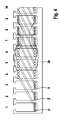
- FIG. 4 is a schematic cross-sectional view of the second embodiment of the two-layer lap winding according to FIG. 3 with a diagrammatic representation of the coil connections (wiring) in a strip-like stator member;
- FIG. 5 is a schematic side view of a third embodiment of a two-layer lap winding
- FIG. 6 is a second side view of the two-layer lap winding from FIG. 5 ;
- FIG. 7 is an end view of the lap winding according to FIG. 6 ;
- FIG. 8 is a schematic cross-sectional view of the third embodiment of the lap winding according to FIGS. 5 to 7 with a diagrammatic representation of the coil connections (wiring) and their positions in a strip-like stator member;
- FIG. 9 is a plan view of the substantially flat two-layer lap winding according to FIGS. 5 to 8 ;
- FIG. 10 is a block diagram of a manufacturing method for making a stator with the two-layer lap winding.
- FIG. 11 is a view of an example of a wire coil.
- a so-called winding bar 10 which acts as an aid, for making a multiphase two-layer lap winding for an electrical machine, is shown in detail in FIG. 1 .
- the lap winding 12 comprises three-phase windings 14 in the embodiment shown in FIG. 1 . These three-phase windings 14 each have a winding beginning U, Z or V.
- the individual phase windings 14 comprise coil units 16 and coil connectors 18 .
- Each phase winding 14 has a so-called first coil unit 20 and second coil unit 22 .
- the first coil units 20 and the second coil units 22 are wired alternately with each other and connected with each other by coil connectors 18 .
- a first coil unit 20 in one phase winding is connected with a coil connector 18 to a second coil unit 22 , which again is connected by another coil connector 18 with another first coil unit 20 .
- FIG. 1 shows the lap winding 12 , which is made as follows:
- First a first coil unit 20 with a predetermined number of loops is wound around the winding bar 10 at a first position P 1 .
- the first coil unit 20 at the position P 1 is looped around the winding bar 10 so that that six coil sides 24 are laid on the winding bar 10 .
- a following coil connector 18 is connected to this first coil unit 20 of the first phase winding 14 , which is similarly part of the first phase winding 14 and which is laid in a first direction.
- This first direction corresponds also to the direction, in which the first coil unit 20 is wound. In FIG. 1 this direction is to the right. This first direction later corresponds to the circumferential direction around a stator of an electrical machine.
- a coil unit 16 of another phase winding 14 is wound over the flat wound coil connector 18 at a position P 2 .
- This coil unit 16 is again a first coil unit 20 .
- the winding beginning U is spaced a distance S from the winding beginning Z of the first coil unit 20 of the second phase winding 14 .
- six coil sides are wound around the winding bar 10 and also looped or slung around the already laid coil connector 18 of the first phase winding 14 .
- Another coil connector 18 is connected to the first coil unit 20 of the second phase winding 14 , similar to that already connected in the first phase winding.
- This other coil connector 18 extends from the first coil unit 20 of the second phase winding 14 and is similarly laid in the already mentioned first direction.
- the winding beginning Z is spaced a distance S from the winding beginning V of the third phase winding 14 . From this position P 3 as many coil sides 14 are laid on the winding bar 10 so that a total of six coil sides 24 are laid on the winding bar 10 .
- the arising first coil unit 20 of the third phase winding 14 is slung or laid around the already laid coil connectors 18 of the first and second phase windings 14 , which extend from the first coil units 20 of those phase windings.
- a further coil connector 18 is laid from the first coil unit 20 of the third phase winding, which extends again in the first direction.
- the positions P 1 , P 2 and P 3 are preferably—like the coil beginnings U, Z and V—spaced about a distance S from each other.
- first a first phase winding 14 is completely wound, subsequently the second phase winding is completely wound and then finally—in a three phase winding—the third phase winding 14 is completely wound.
- the characteristic arrangement of the coil units 16 of the phase winding 14 shown in FIG. 2 arises. After swinging the second coil sides 27 in a three phase lap winding 12 the second coil sides 27 of the first coil unit 20 of the first phase winding 14 lie over the first coil sides 26 of the second coil unit 22 of the first phase winding 14 . The same goes analogously from the coil sides 24 of the first coil unit 20 of the second phase winding 14 and for the first coil unit 20 of the third phase winding 14 .
- FIG. 3 another embodiment of the lap winding 12 according to the invention is shown, which is very similar to the lap winding 12 shown in FIG. 1 .
- a first phase winding 14 is started, which is the phase winding 14 with the winding beginning V, not the phase winding 14 with the winding beginning U.
- the first coil sides 26 of the first coil unit 20 are first laid in the groove 1 of a strip-like stator packet 29 in the case of the lap winding 12 according to FIG. 1 (see also FIG. 2 ).
- the first coil sides 26 of the first coil unit 20 of the first phase winding 14 are laid in the groove 3 of a strip-like stator packet.
- This phase winding 14 starts with the winding beginning V.
- the phase windings 14 are indeed wound as before in the first direction, which corresponds also to the right in FIG. 3 .
- the second phase winding is started with the corresponding winding beginning Z after winding the first phase winding 14 .
- the third phase winding 14 is started with the winding beginning U at a position, which is removed two steps S from the first coil unit 20 of the first wound phase winding 14 .
- a first coil unit 20 is wound at the position P 3 of a first phase winding 14 and subsequently a coil connector 18 of the first phase winding 14 is laid in the first direction.
- a second coil unit 22 is wound spaced a distance of three steps S from the first coil unit 20 of the first phase winding 14 .
- a further coil connector 18 extends from the second coil unit 22 , which is laid in the first direction. This alternating sequence of first and second coil units 20 and 22 is repeated as long as required.
- each phase winding 14 requires six first coil units 20 and six second coil units 22 .
- the second phase winding 14 with the winding beginning Z is wound over the first phase winding 14 .
- it is started at a position P 2 spaced with a step S from P 3 in an opposite direction from the first direction.
- a first coil unit 20 is wound, which has a following coil connector 18 connected with a second coil unit 22 .
- the coil connectors 18 generally lie over the first coil units 20 and/or under the second coil units 22 .
- the coil connectors 18 are correspondingly not gripped or embraced by the coil units of the first phase winding 14 .
- the third phase winding 14 is wound with the winding beginning U.
- the winding beginning U is spaced about two steps S from the winding beginning V of the first phase winding 14 .
- the first coil unit 20 is wound at this position P 1 .
- Another coil connector 18 follows it and is laid in the first direction. This coil connector 18 overlaps the first coil units 20 of the first and second phase winding 14 .
- the second coil unit 22 of the third phase winding overlaps or covers necessarily the coil connectors 18 of the first and second phase windings 14 between the first coil unit 20 and/or the second coil unit 22 .
- the winding directions of the first coil units 20 are opposite to the winding directions of the second coil units 22 .
- FIG. 4 shows how the lap winding 12 made according to the method of FIG. 3 is laid in the already mentioned strip-like stator member 29 .
- the twisting or turning of the second coil sides 27 occurs exactly as in the lap winding 12 according to the embodiment shown in FIG. 1 , so that no further explanations are needed.
- the coil connectors 18 this results already from FIG. 3 —are at other positions outside of the first and second coil units 20 and 22 .
- FIG. 5 a third schematic embodiment of a lap winding 12 is shown.
- a first phase winding 14 is wound starting with the winding beginning U.
- a first coil unit 20 is slung around the winding bar 10 at position P 1 in a first step.
- a first coil connector 18 extends from the latter second coil sides 27 of the first coil unit 20 .
- This connector is laid in a first direction—to the right in FIG. 5 . This happens immediately in the winding of the first coil unit 20 .
- the coil connector 18 is laid to reach the starting position A 1 of the second coil unit 22 of the first phase winding 14 .
- the first coil unit 20 of the second phase winding 14 is wound.
- the winding beginning U of the first phase winding 14 is spaced with the step S from the winding beginning Z of the second phase winding 14 .
- Starting from the winding beginning Z also three first winding sides 26 and three second winding sides 27 are laid around the winding beam 10 .
- the first coil connector 18 is laid between the first coil unit 20 and the second coil unit 22 of the second phase winding 14 .
- the coil connector 18 of the first phase winding 14 is thus embrace or overlapped by the first coil unit 20 of the second phase winding 14 .
- a coil connector 18 extends, which is laid in the first direction.
- This coil connector 18 reaches to the starting position A 2 of the second coil unit 22 of the second phase winding 14 .
- the winding of the third phase winding 14 is started, in which the coil connector 18 between the first coil unit 20 and the second coil unit 22 ends at a starting position A 3 of the second coil unit 22 .
- the first coil unit 20 of the third phase winding 14 embraces or engages the second coil connectors 18 of the previously wound first and second phase winding 14 .
- the second coil unit 22 of the first phase winding 14 is wound starting from the starting position A 1 .
- this second coil unit 22 comprises three first coil sides 26 and three second coil sides 27 .
- the second coil unit 22 of the first phase winding 14 is consequently laid over the coil connectors 18 between first and second coil units 20 and 22 of the second and third phase windings 14 .
- the second coil unit 22 of the first phase winding 14 embraces these coil connectors 18 .
- After winding the final coil side 24 of the second coil unit 22 of the first phase winding 14 a coil connector 18 is laid in the first direction until the starting position A 4 is reached.
- the next first coil unit 20 of the first phase winding with another subsequently connected coil connector 18 is wound at starting position A 4 .
- the second coil unit 22 of the second phase winding 14 comprising three first coil units 26 and three second coil units 27 is wound—starting from the starting position A 2 —.
- the second coil unit 22 of the second phase winding 14 embraces the coil connector 18 of the third phase winding 14 between the first coil unit 20 and the second coil unit 22 of the third phase winding 14 . It also embraces the coil connector 18 extending from the second coil unit 22 of the first phase winding 14 .
- the second coil unit 22 of the third phase winding 14 is wound around the winding bar 10 with three first coil sides 26 and three second coil sides 27 .
- a coil connector 18 is similarly laid extending from it in the first direction.
- the second coil unit 22 of the third phase winding 14 embraces in a similar way the coil connectors 18 from the respective coil units 22 of the first and second phase windings 14 .
- the lap winding 12 is designed for a stator having 36 grooves. Analogously the lap winding 12 for a stator having 48 grooves should in an analogous manner be provided with eight first coil units 20 and eight second coil units 22 for each phase winding 14 .
- FIG. 6 The winding bar 10 with the lap winding 12 of FIG. 5 on it is shown in FIG. 6 .
- the arrangement of the first coil units 20 and second coil units 22 of the individual phase windings 14 is clearly shown.
- FIG. 7 An end-on view of the lap winding 12 wound on the winding bar 10 as seen in the direction VII in FIG. 6 is shown in FIG. 7 .
- the lifting of the individual coil units 16 when they are guided over the coil connectors 18 can be clearly seen in FIG. 7 .
- FIG. 8 an arrangement of a lap winding 12 in a strip-like stator packet 29 is illustrated in FIG. 8 .
- the process described with the aid of FIGS. 5 to 7 produces a lap winding 12 , in which the second coil sides 27 are tilted or swung around the first coil sides 26 , as already described in relation to the previously described lap windings.
- the coil connectors 18 are covered by coil sections and thus are arranged within the coil or winding ends of the lap winding 12 and/or the phase windings 14 .
- FIG. 9 shows an unwinding of the lap winding 12 of FIG. 8 in a plan view.
- This plan view corresponds approximately to a view from the radial interior to the radial exterior in a circular stator.
- FIG. 9 is somewhat simplified and shows the position of the first coil sides 26 in the so-called groove base with a broken line and the position of the second coil sides 27 with a solid line. The representation is simplified in as much as the actual number of turns or coils of the first coil unit 20 or the second coil unit 22 is not shown.
- the coil connectors 18 are collectively within or inside regions of the coil units 16 forming the winding ends 31 .
- a coil overhang formed from three coil units 16 and/or accompanying second coil sides 27 is formed, which, as shown in FIG. 9 , is laid on the first coil sides 26 of the first coil unit 20 in the grooves 1 , 2 and 3 .
- the numbers 1 to 21 and 33 to 26 in the center of the lap winding 12 designate corresponding grooves of 36-groove stator member.
- FIG. 10 A manufacturing process for making a stator is illustrated in FIG. 10 .
- a strip-like stator member 29 provided with grooves and teeth is prepared.
- a two-layer lap winding 12 made according to the method of the present invention is laid in the grooves.
- a third step S 3 the assembly comprising the stator member 29 and the lap winding are bent around so that a hollow cylindrical stator is formed.
- a method for making a two-layer lap winding 12 for a multiphase electrical machine in which the two-layer winding is made from a wire bundle, which is wound on a winding bar 10 .
- a first coil unit 20 of a first phase winding 14 is wound on the winding bar 10 and then a coil connector 18 of the first phase winding 14 is laid in a first direction.
- coil units 16 , 22 of a further phase winding 14 are wound over coil connectors 18 .
- at least one coil unit 16 embraces two coil connectors 18 of adjacent coil units 20 and/or 22 .
- Respective coil connectors 18 connect two successive coil units 20 and 22 .
- the first phase winding is completely wound and then at least one further complete phase winding 14 is wound.
- the coil unit 16 wound in one of the further steps is a first coil unit 20 of a further phase winding 14 and a coil connector is again laid in the first or winding direction.
- a coil connector is again laid in the first or winding direction.
- This embodiment further provides that, after the winding of respective first coil units 20 of all phases, coil connectors 18 extend from all of these first coil units 20 to starting positions A 1 , A 2 , A 3 for laying respective second coil units 22 of each phase winding 14 .
- the second coil units 22 of the phase windings 14 are wound in the same sequence as the first coil units 20 of the phase windings 14 .
- the respective coil connectors 18 extend from the second coil units 22 to reach starting positions of corresponding further first coil units 20 of the phase windings.
- each phase winding 14 has first coil units 20 and second coil units 22 arranged alternately following each other and connected with each other.
- Each coil unit 20 and/or 22 has at least one first coil side 26 and/or second coil side 27 , which are found on opposite sides on the winding bar 10 .
- the winding 12 is removed from the winding bar 10 .
- the first and second coil units 10 and 22 are swung so that at least one second coil side of a coil unit 16 is laid on the at least one first coil side 26 of the next coil unit 16 in the winding direction.
- the winding direction is also the circumferential direction of the stator member.
- wire bundle 33 comprising at least two fastened together wires can be used, as shown in FIG. 11 .
- the term “wire bundle” can also mean an individual wire in this description.
- German Patent Application 103 29 576.3 of Jun. 30, 2003 is incorporated here by reference.
- This German Patent Application describes the invention described hereinabove and claimed in the claims appended hereinbelow and provides the basis for a claim of priority for the instant invention under 35 U.S.C. 119.
Landscapes
- Engineering & Computer Science (AREA)
- Power Engineering (AREA)
- Manufacturing & Machinery (AREA)
- Manufacture Of Motors, Generators (AREA)
- Windings For Motors And Generators (AREA)
Applications Claiming Priority (2)
| Application Number | Priority Date | Filing Date | Title |
|---|---|---|---|
| DE10329576.3 | 2003-04-30 | ||
| DE10329576A DE10329576A1 (de) | 2003-06-30 | 2003-06-30 | Verfahren zum Herstellen einer zweischichtigen Schleifenwicklung |
Publications (2)
| Publication Number | Publication Date |
|---|---|
| US20040216302A1 US20040216302A1 (en) | 2004-11-04 |
| US7302749B2 true US7302749B2 (en) | 2007-12-04 |
Family
ID=33305235
Family Applications (1)
| Application Number | Title | Priority Date | Filing Date |
|---|---|---|---|
| US10/842,128 Expired - Lifetime US7302749B2 (en) | 2003-06-30 | 2004-05-10 | Method of making a two-layer lap winding for a multiphase electrical machine |
Country Status (5)
| Country | Link |
|---|---|
| US (1) | US7302749B2 (fr) |
| EP (1) | EP1494337B1 (fr) |
| JP (1) | JP4603810B2 (fr) |
| DE (2) | DE10329576A1 (fr) |
| ES (1) | ES2348718T3 (fr) |
Cited By (3)
| Publication number | Priority date | Publication date | Assignee | Title |
|---|---|---|---|---|
| JP2005027494A (ja) * | 2003-06-30 | 2005-01-27 | Robert Bosch Gmbh | 二層の重ね巻線を製作するための方法 |
| US20080136283A1 (en) * | 2006-12-12 | 2008-06-12 | Nidec Corporation | Motor |
| CN102246398A (zh) * | 2008-12-19 | 2011-11-16 | 罗伯特·博世有限公司 | 制作多相系统分布叠绕组的方法 |
Families Citing this family (10)
| Publication number | Priority date | Publication date | Assignee | Title |
|---|---|---|---|---|
| DE102004035084A1 (de) | 2004-07-20 | 2006-02-16 | Elmotec Statomat Vertriebs Gmbh | Verfahren und Vorrichtung zur Herstellung einer Spulenwicklung für Statoren oder Rotoren elektrischer Maschinen sowie damit herzustellender Stator oder Rotor |
| DE102004059087A1 (de) * | 2004-12-08 | 2006-06-14 | Robert Bosch Gmbh | Wickelvorrichtung für eine Feldspule, Fertigungsvorrichtung und elektrische Maschine |
| JP5095276B2 (ja) * | 2007-06-27 | 2012-12-12 | 本田技研工業株式会社 | ステータおよびその巻線方法 |
| DE102009055043A1 (de) | 2008-12-19 | 2010-06-24 | Robert Bosch Gmbh | Verfahren zur Herstellung einer verteilten Schleifenwicklung für mehrphasige Systeme |
| DE102009024230A1 (de) * | 2009-05-29 | 2010-12-02 | Robert Bosch Gmbh | Verfahren zur Herstellung einer Ständerwicklung einer elektrischen Maschine, insbesondere zur Herstellung eines Wechselstromgenerators |
| DE102009024231A1 (de) * | 2009-05-29 | 2010-12-09 | Robert Bosch Gmbh | Verfahren zur Herstellung einer Ständerwicklung einer elektrischen Maschine, insbesondere eines Wechselstromgenerators |
| DE102010053717A1 (de) * | 2010-12-01 | 2012-06-06 | Robert Bosch Gmbh | Ständerwicklung mit mehreren Phasenwicklungen |
| DE102013226875A1 (de) * | 2013-12-20 | 2015-07-09 | Robert Bosch Gmbh | Verfahren zur Herstellung einer mehrphasigen Wicklung für einen Stator einer elektrischen Maschine |
| LU101030B1 (de) * | 2018-12-12 | 2020-06-12 | Ulrich Klose | Kupfersparwicklung |
| DE102019132683A1 (de) * | 2019-08-08 | 2021-02-11 | stoba e-Systems GmbH | Elektromotor und Stator mit mehrfachbelegten Nuten |
Citations (7)
| Publication number | Priority date | Publication date | Assignee | Title |
|---|---|---|---|---|
| DE1563094A1 (de) | 1965-04-13 | 1970-05-27 | Futoshi Yasukawa | Statorwicklung fuer einen Elektromtor |
| DE1613391A1 (de) | 1967-05-26 | 1970-10-08 | Siemens Ag | Verfahren zum Herstellen einer loetstellenfreien Mehrphasenwicklung fuer elektrischeMaschinen |
| WO1991009449A1 (fr) | 1989-12-15 | 1991-06-27 | Shramo Daniel J | Moteur electrique a large entrefer, sans balais et sans fente |
| US5197180A (en) | 1991-09-13 | 1993-03-30 | Faraday Energy Foundation | Method for making an electric motor winding |
| US5319844A (en) * | 1985-12-23 | 1994-06-14 | Unique Mobility, Inc. | Method of making an electromagnetic transducer |
| US5425165A (en) * | 1989-12-15 | 1995-06-20 | Shramo; Daniel J. | Method of making a slotless, brushless, large air-gap electric motor |
| US20030071534A1 (en) | 2000-01-20 | 2003-04-17 | Helmut Kreuzer | Method for producing a magnetically excitable core comprising a core winding for an electric machine |
Family Cites Families (2)
| Publication number | Priority date | Publication date | Assignee | Title |
|---|---|---|---|---|
| JP4151489B2 (ja) * | 2002-06-26 | 2008-09-17 | 株式会社デンソー | 車両用交流発電機 |
| DE10329576A1 (de) * | 2003-06-30 | 2005-02-24 | Robert Bosch Gmbh | Verfahren zum Herstellen einer zweischichtigen Schleifenwicklung |
-
2003
- 2003-06-30 DE DE10329576A patent/DE10329576A1/de not_active Withdrawn
-
2004
- 2004-03-04 ES ES04005087T patent/ES2348718T3/es not_active Expired - Lifetime
- 2004-03-04 DE DE502004011415T patent/DE502004011415D1/de not_active Expired - Lifetime
- 2004-03-04 EP EP04005087A patent/EP1494337B1/fr not_active Expired - Lifetime
- 2004-03-24 JP JP2004086801A patent/JP4603810B2/ja not_active Expired - Fee Related
- 2004-05-10 US US10/842,128 patent/US7302749B2/en not_active Expired - Lifetime
Patent Citations (7)
| Publication number | Priority date | Publication date | Assignee | Title |
|---|---|---|---|---|
| DE1563094A1 (de) | 1965-04-13 | 1970-05-27 | Futoshi Yasukawa | Statorwicklung fuer einen Elektromtor |
| DE1613391A1 (de) | 1967-05-26 | 1970-10-08 | Siemens Ag | Verfahren zum Herstellen einer loetstellenfreien Mehrphasenwicklung fuer elektrischeMaschinen |
| US5319844A (en) * | 1985-12-23 | 1994-06-14 | Unique Mobility, Inc. | Method of making an electromagnetic transducer |
| WO1991009449A1 (fr) | 1989-12-15 | 1991-06-27 | Shramo Daniel J | Moteur electrique a large entrefer, sans balais et sans fente |
| US5425165A (en) * | 1989-12-15 | 1995-06-20 | Shramo; Daniel J. | Method of making a slotless, brushless, large air-gap electric motor |
| US5197180A (en) | 1991-09-13 | 1993-03-30 | Faraday Energy Foundation | Method for making an electric motor winding |
| US20030071534A1 (en) | 2000-01-20 | 2003-04-17 | Helmut Kreuzer | Method for producing a magnetically excitable core comprising a core winding for an electric machine |
Cited By (6)
| Publication number | Priority date | Publication date | Assignee | Title |
|---|---|---|---|---|
| JP2005027494A (ja) * | 2003-06-30 | 2005-01-27 | Robert Bosch Gmbh | 二層の重ね巻線を製作するための方法 |
| US20080136283A1 (en) * | 2006-12-12 | 2008-06-12 | Nidec Corporation | Motor |
| US7646127B2 (en) * | 2006-12-12 | 2010-01-12 | Nidec Corporation | Winding for three phase motor |
| CN102246398A (zh) * | 2008-12-19 | 2011-11-16 | 罗伯特·博世有限公司 | 制作多相系统分布叠绕组的方法 |
| US20110302767A1 (en) * | 2008-12-19 | 2011-12-15 | Robert Bosch Gmbh | Method for producing a distributed lap winding for polyphase systems |
| US8914967B2 (en) * | 2008-12-19 | 2014-12-23 | Robert Bosch Gmbh | Method for producing a distributed lap winding for polyphase systems |
Also Published As
| Publication number | Publication date |
|---|---|
| EP1494337A3 (fr) | 2006-08-02 |
| DE502004011415D1 (de) | 2010-09-02 |
| EP1494337B1 (fr) | 2010-07-21 |
| ES2348718T3 (es) | 2010-12-13 |
| JP2005027494A (ja) | 2005-01-27 |
| DE10329576A1 (de) | 2005-02-24 |
| US20040216302A1 (en) | 2004-11-04 |
| JP4603810B2 (ja) | 2010-12-22 |
| EP1494337A2 (fr) | 2005-01-05 |
Similar Documents
| Publication | Publication Date | Title |
|---|---|---|
| US6201332B1 (en) | AC generator stator for vehicle | |
| JP5070248B2 (ja) | 回転電機とその製造方法 | |
| JP5234173B2 (ja) | ステータ及びそれに使用される単位コイルの製造方法 | |
| US6373164B1 (en) | Stator for dynamo-electric machine | |
| JP5537952B2 (ja) | 固定子と、巻線素子からなり、固定子溝に装入されている、固定子巻線とを備えた交流発電機ならびに本発明による固定子の製造方法 | |
| US7302749B2 (en) | Method of making a two-layer lap winding for a multiphase electrical machine | |
| US10637320B2 (en) | Stator assemblies for three phase dynamoelectric machines and related winding methods | |
| US11056945B2 (en) | Stator of rotary electric machine and method of manufacturing the same | |
| US20070262664A1 (en) | Stator for an electrical machine | |
| US7225526B2 (en) | Method of producing winding of dynamo-electric machine | |
| JP2012152028A (ja) | 回転電機 | |
| EP2833521A1 (fr) | Stator | |
| US10256682B2 (en) | Stator assemblies for three phase dynamoelectric machines and related winding methods | |
| JP2005312278A (ja) | 回転電機の集中巻き型ステータコイル | |
| US20080036323A1 (en) | Permanent Magnet Synchronous Machine with Flat-Wire Windings | |
| US7256521B2 (en) | Motor or generator and method of producing the same | |
| US7726005B2 (en) | Method for making an electromagnetically excitable core of an electrical machine with a multiphase winding | |
| JPH104645A (ja) | 電動機のステータ | |
| CN106849435A (zh) | 旋转电机 | |
| US8946965B2 (en) | Armature of electric motor and electric motor | |
| JP2019009962A (ja) | 三相モータの結線構造、結線方法及び三相モータ | |
| CN107112869B (zh) | 用于卷绕绕组架的方法 | |
| JP2001275291A (ja) | 電動機の固定子 | |
| CN112583164A (zh) | 扁铜漆包线电机绕组及其制造方法 | |
| JP2003102152A (ja) | ステータへのコイル巻線方法 |
Legal Events
| Date | Code | Title | Description |
|---|---|---|---|
| AS | Assignment |
Owner name: ROBERT BOSCH GMBH, GERMANY Free format text: ASSIGNMENT OF ASSIGNORS INTEREST;ASSIGNORS:KREUZER, HELMUT;RAU, EBERHARD;BEZNER, REINHARD;REEL/FRAME:015315/0035;SIGNING DATES FROM 20040407 TO 20040421 |
|
| STCF | Information on status: patent grant |
Free format text: PATENTED CASE |
|
| FPAY | Fee payment |
Year of fee payment: 4 |
|
| FPAY | Fee payment |
Year of fee payment: 8 |
|
| AS | Assignment |
Owner name: SEG AUTOMOTIVE GERMANY GMBH, GERMANY Free format text: ASSIGNMENT OF ASSIGNORS INTEREST;ASSIGNOR:ROBERT BOSCH GMBH;REEL/FRAME:044510/0921 Effective date: 20171023 |
|
| MAFP | Maintenance fee payment |
Free format text: PAYMENT OF MAINTENANCE FEE, 12TH YEAR, LARGE ENTITY (ORIGINAL EVENT CODE: M1553); ENTITY STATUS OF PATENT OWNER: LARGE ENTITY Year of fee payment: 12 |