US7311123B2 - Flexible tubular pipe - Google Patents
Flexible tubular pipe Download PDFInfo
- Publication number
- US7311123B2 US7311123B2 US10/432,755 US43275503A US7311123B2 US 7311123 B2 US7311123 B2 US 7311123B2 US 43275503 A US43275503 A US 43275503A US 7311123 B2 US7311123 B2 US 7311123B2
- Authority
- US
- United States
- Prior art keywords
- tube
- hollow profiled
- hollow
- pipe
- flexible
- Prior art date
- Legal status (The legal status is an assumption and is not a legal conclusion. Google has not performed a legal analysis and makes no representation as to the accuracy of the status listed.)
- Expired - Fee Related, expires
Links
- 239000002184 metal Substances 0.000 claims abstract description 21
- 238000004804 winding Methods 0.000 claims description 29
- 239000000835 fiber Substances 0.000 claims description 4
- 230000007935 neutral effect Effects 0.000 claims description 4
- 238000004519 manufacturing process Methods 0.000 description 10
- 230000000694 effects Effects 0.000 description 5
- 239000012530 fluid Substances 0.000 description 5
- 239000000463 material Substances 0.000 description 3
- 238000003466 welding Methods 0.000 description 3
- 229930195733 hydrocarbon Natural products 0.000 description 2
- 150000002430 hydrocarbons Chemical class 0.000 description 2
- 238000009434 installation Methods 0.000 description 2
- 238000000034 method Methods 0.000 description 2
- 230000003014 reinforcing effect Effects 0.000 description 2
- 238000007789 sealing Methods 0.000 description 2
- 230000000295 complement effect Effects 0.000 description 1
- 230000006835 compression Effects 0.000 description 1
- 238000007906 compression Methods 0.000 description 1
- 239000004020 conductor Substances 0.000 description 1
- 230000002500 effect on skin Effects 0.000 description 1
- 239000013529 heat transfer fluid Substances 0.000 description 1
- 238000010438 heat treatment Methods 0.000 description 1
- 230000006698 induction Effects 0.000 description 1
- 238000005259 measurement Methods 0.000 description 1
- 230000000149 penetrating effect Effects 0.000 description 1
- 239000003208 petroleum Substances 0.000 description 1
- 230000002787 reinforcement Effects 0.000 description 1
- 238000005096 rolling process Methods 0.000 description 1
- 229910001220 stainless steel Inorganic materials 0.000 description 1
- 239000010935 stainless steel Substances 0.000 description 1
- 230000003068 static effect Effects 0.000 description 1
- 238000005491 wire drawing Methods 0.000 description 1
Images




Classifications
-
- F—MECHANICAL ENGINEERING; LIGHTING; HEATING; WEAPONS; BLASTING
- F16—ENGINEERING ELEMENTS AND UNITS; GENERAL MEASURES FOR PRODUCING AND MAINTAINING EFFECTIVE FUNCTIONING OF MACHINES OR INSTALLATIONS; THERMAL INSULATION IN GENERAL
- F16L—PIPES; JOINTS OR FITTINGS FOR PIPES; SUPPORTS FOR PIPES, CABLES OR PROTECTIVE TUBING; MEANS FOR THERMAL INSULATION IN GENERAL
- F16L11/00—Hoses, i.e. flexible pipes
- F16L11/04—Hoses, i.e. flexible pipes made of rubber or flexible plastics
- F16L11/08—Hoses, i.e. flexible pipes made of rubber or flexible plastics with reinforcements embedded in the wall
- F16L11/081—Hoses, i.e. flexible pipes made of rubber or flexible plastics with reinforcements embedded in the wall comprising one or more layers of a helically wound cord or wire
- F16L11/083—Hoses, i.e. flexible pipes made of rubber or flexible plastics with reinforcements embedded in the wall comprising one or more layers of a helically wound cord or wire three or more layers
-
- F—MECHANICAL ENGINEERING; LIGHTING; HEATING; WEAPONS; BLASTING
- F16—ENGINEERING ELEMENTS AND UNITS; GENERAL MEASURES FOR PRODUCING AND MAINTAINING EFFECTIVE FUNCTIONING OF MACHINES OR INSTALLATIONS; THERMAL INSULATION IN GENERAL
- F16L—PIPES; JOINTS OR FITTINGS FOR PIPES; SUPPORTS FOR PIPES, CABLES OR PROTECTIVE TUBING; MEANS FOR THERMAL INSULATION IN GENERAL
- F16L11/00—Hoses, i.e. flexible pipes
- F16L11/14—Hoses, i.e. flexible pipes made of rigid material, e.g. metal or hard plastics
- F16L11/16—Hoses, i.e. flexible pipes made of rigid material, e.g. metal or hard plastics wound from profiled strips or bands
-
- F—MECHANICAL ENGINEERING; LIGHTING; HEATING; WEAPONS; BLASTING
- F16—ENGINEERING ELEMENTS AND UNITS; GENERAL MEASURES FOR PRODUCING AND MAINTAINING EFFECTIVE FUNCTIONING OF MACHINES OR INSTALLATIONS; THERMAL INSULATION IN GENERAL
- F16L—PIPES; JOINTS OR FITTINGS FOR PIPES; SUPPORTS FOR PIPES, CABLES OR PROTECTIVE TUBING; MEANS FOR THERMAL INSULATION IN GENERAL
- F16L11/00—Hoses, i.e. flexible pipes
- F16L11/24—Hoses, i.e. flexible pipes wound from strips or bands
Definitions
- the present invention relates to a flexible tubular pipe which can be preferably used in deep-sea applications, for depths of between 1000 and 3000 m, although it can also be used for depths of less than 1000 m.
- Such flexible tubular pipes are used in subsea oil production installations for transporting fluids such as hydrocarbons.
- the present invention relates to a flexible tubular pipe which can be preferably used in deep-sea applications, for depths of between 1000 and 3000 m, although it can also be used for depths of less than 1000 m.
- Such flexible tubular pipes are used in subsea oil production installations for transporting fluids such as hydrocarbons.
- the reinforcing wires must have a high moment of inertia in order to withstand the external pressure and a low weight in order to reduce the total weight of the flexible pipe so as to improve the performance of the pipelaying means and allow the flexible pipe to be self-supporting.
- a first solution has consisted in using a shaped wire, the cross-section of which is in the form of an I, as described in FR-A-2 782 142.
- a shaped wire has an acceptable moment of inertia/weight ratio but the manufacturing cost is very high because of the fact that it is obtained by rolling or wire drawing.
- the internal carcass is formed from doubly interlocking metal strips, by making a flat metal tape, such as a stainless steel strip, undergo plastic deformation in order to give it the shape of a doubly interlocking profiled strip, and then by spiraling the profiled strip, that is to say winding it helically with a short pitch with interlocking of the profiled metal strips. After two consecutive turns have been interlocked, a final plastic deformation of the strip is carried out in order to complete the interlocking.
- a flat metal tape such as a stainless steel strip
- Patent FR 2 665 237 it is recommended to produce a tubular metal carcass comprising at least one box section wound in a helix with a short pitch, said metal carcass being obtained by means of two complementary profiled strips wound helically with a short pitch.
- profiled strips are described and shown in that document, some of which, such as for example those in FIGS. 8 and 9 , consisting of a strip in the form of an elongated S and having a box section at a first end and an upwardly curved fastening edge at the other end, the fastening edge penetrating a dish formed by the box section and the transverse bar of the of the preceding turn.
- the curved fastening edge may rest on the bottom of the dish ( FIG. 9 ) or it may not be in contact with said bottom ( FIG. 8 ).
- cross-sections of the box sections provided at one or both ends of each profiled strip are square or rectangular cross-sections.
- box-section profiled strips have been satisfactory, they have been found to have certain drawbacks.
- a box section is formed by parts of the same turn of the profiled strip and comprises an upper wall, a lower wall and side walls and when an external force is applied to one of the upper and/or lower walls, such as a compressive or crushing force or else a force generated by the underpressure fluid, buckling of the side walls or faces and/or the upper or lower walls of the box section may then occur, thereby reducing, at least locally, the crush resistance of the internal carcass.
- the box-section strip adopts the shape of a pair of spectacles.
- This profile is produced from a strip whose free edges are welded to this same profile so as to give the profile good stability for laying.
- the welding operation is difficult to implement and considerably increases the manufacturing cost.
- the spectacles-shaped profile is similar but produced from two tubes, of square cross-section, said tubes being joined together by a strip which is welded to these tubes.
- the welding operations again considerably increase the manufacturing cost.
- these various shapes of the profile do not make it possible to limit the creep of an adjacent sealing sheath. It is sought to prevent such creep as far as possible, mainly in the case of the pressure vault. It should also be noted that no information is provided regarding the width/thickness ratio of the strip, although this has become important in order to ensure stability of the profile during pipe laying, so as to prevent the buckling effect.
- the object of the present invention is to provide a profile which makes it possible to simplify the spiraling operations while still having a high moment of inertia/pitch ratio, similar to that obtained with conventional shaped wires of equivalent height, and a high moment of inertia/weight ratio which is needed in particular for great depths.
- the subject of the present invention is a flexible tubular pipe comprising a metal box section spiraled in a helix about a longitudinal axis of said flexible pipe and it is characterized in that the box section consists of at least one interlocked hollow profiled tube.
- the invention can be carried out in order to produce a pressure vault or a carcass with an interlocked tube of any cross-section.
- One advantage of the present invention lies in the fact that an inexpensive tube is used which is profiled, for example, using a roll train or a die to the desired shape. In this way it is possible to optimize the moment of inertia of the profile, and therefore to improve the moment of inertia/weight ratio, and-to give it a shape suitable for the interlocking of the winding turns to be carried out simply and without any difficulty.
- Another advantage of the present invention is that it is no longer necessary to provide a system for holding the box section, which in the prior art is produced by stopping or welding it, which simplifies the manufacture, for example, of the pressure vault produced using the tube according to the invention, so that the manufacturing cost is considerably reduced.
- Another advantage is that the moment of inertia/winding pitch ratio is optimized, it being possible for the interlocked profile tube to limit the influence of the necessary gap between the turns in order to give the pipe a certain flexibility.
- Another advantage lies in the fact that the hollow profiled tube is approximately symmetrical and in that the compression regions compensate for the tension regions. In this way, the winding or spiraling is easier to implement.
- FIG. 1 is a schematic sectional view of a pressure vault produced by the helical winding of at least one hollow profiled tube according to a first embodiment of the invention
- FIG. 2 is a schematic sectional view of a pressure vault produced by the helical winding of at least one hollow profiled tube according to a second embodiment of the invention
- FIG. 3 is a schematic sectional view of a pressure vault produced by the helical winding of at least one hollow profiled tube according to a third embodiment of the invention
- FIG. 4 is a schematic sectional view of a pressure vault produced by the helical winding of at least one hollow profiled tube according to a fourth embodiment of the invention.
- FIG. 5 is a schematic sectional view of a pressure vault produced by the helical winding of at least one hollow profiled tube according to a fifth embodiment of the invention.
- FIG. 6 is a schematic sectional view of a pressure vault produced by the helical winding of at least one hollow profiled tube according to a sixth embodiment of the invention.
- FIGS. 7 , 8 , 9 and 11 are schematic sectional views of a hollow profiled tube according to different embodiments of the invention.
- FIGS. 10 and 12 are schematic sectional views of a pressure vault produced by the helical winding of at least one hollow profiled tube according to another embodiment.
- interlocked is understood hereafter to mean either a profile that is not interlockable, but which would be interlocked by one or more fasteners, or an interlockable profile or a self-interlockable profile.
- the hollow profiled tubes are not interlockable and therefore require one or two fasteners of suitable cross-section in order to link two consecutive turns of the same winding together when a single hollow profiled tube is used or of two windings when two hollow profiled tubes are used.
- Such non-interlockable profile tubes may be compared with hoop reinforcements well known to experts and described in API 17 J.
- the hollow profiled tubes 1 and 2 may each have a trapezoidal cross-section, as shown in FIG. 1 , the trapezoidal cross-section being obtained, for example, from a tube of circular cross-section which has been deformed by a roll train or in a die. Each tube is helically wound about the longitudinal axis A-A of the flexible pipe, which has not been shown but which is described according to the various types in the API 17 J. To produce a pressure vault, the two tubes 1 and 2 are wound or spiraled with a short pitch. The two tubes 1 and 2 of the two consecutive turns 3 and 4 are joined together or fastened by means of a first fastener 5 which goes around the lower faces 6 and 7 of the tubes 1 and 2 . The fastener 5 has an approximately U shape.
- the consecutive turns 4 and 8 are interlocked by means of a fastener 9 , similar to the fastener 5 , but going around the upper faces 10 and 11 of the tubes constituting the next turns.
- the turn 12 is interlocked with the previous turn 8 by a lower fastener 5 , whereas the turn 12 and the next turn 13 are interlocked using an upper fastener 9 .
- the lower fasteners 5 and the upper fasteners 9 have arms 5 ′ and 9 ′ which are inserted sufficiently into the interstices or gaps 14 between the turns, so that good interlocking is achieved.
- the hollow profiled tubes 21 and 21 ′ are similar to those represented in FIG. 1 , but the fastener between two consecutive turns is obtained by means of different fasteners.
- Each hollow profiled tube 21 , 21 ′ is housed in contact in a horizontal part 20 of a fastener 22 , which has two lateral flanges or horizontal parts 23 , 24 located at an upper level with respect to the lower level occupied by the part 20 .
- the flanges 23 , 24 have ends 25 , 26 bent over downward in order to allow interlocking with another U-shaped fastener 27 .
- the turn 21 ′ bears on the fastener 27 and is held in place by the contact on the ends 26 and 25 of the fastener 22 , which may be regarded as adopting the shape of a double S.
- the hollow profiled tubes 30 have a trapezoidal cross-section and two consecutive turns 31 and 32 are interlocked by means of fasteners 33 , each having an end 34 which is raised and then bent over downward, and the other end 35 is simply raised upward, so that two fasteners 33 interlock via their ends.
- the hollow profiled tube 30 nearly bears on the two ends 34 of two consecutive fasteners, whereas the tube 30 of the turn 32 bears on the end 34 , but is away from the end 34 of the other fastener.
- the pressure vault must have a certain gap between the turns in order to give the pipe a certain flexibility, FIG. 3 showing the vault with a minimum pitch (left-hand part) and with a maximum pitch (right-hand part) with the turns 32 and 36 further away.
- the fasteners 40 and 41 are identical and each fastener 40 , 41 has an elevated part 42 made between an upwardly curved end 43 and a bulge 44 of upwardly turned concavity, the turn 45 being placed on the part 42 and bearing on the end 43 and the bulge 44 .
- the low part 46 of the fastener 40 accommodates the elevated part and the associated turn of the other consecutive fastener 41 , as shown in the figure.
- the fasteners 50 adopt the shape of a zeta, each turn 51 being placed between the upper arms 52 and lower arms 53 of the consecutive fasteners.
- the hollow profiled tubes are interlockable or self-interlockable and may be compared with the interlockable shaped wires well known to experts, such as U-, Z- or T-shaped wires.
- each hollow profiled tube 60 of a turn 61 is also trapezoidal in shape, but with a flat horizontal upper face 62 and a lower face 63 which is deformed toward the upper wall so as to create, on the one hand, a kind of bulge 64 for the interlocking by means of an approximately U-shaped fastener 65 , and, on the other hand, to define two hollow regions 66 and 67 .
- the shape of the approximately T-shaped hollow profile 70 has an upper wall 71 which is deformed at two points in order to produce two bulges 72 and 73 , the lower wall 74 being horizontal.
- the cross-section of the hollow profiled tube 80 is a zeta, and therefore is self-interlockable with another profile tube of the same cross-section.
- the right-hand part differs from the left-hand part by the fact that the upper wall 81 has a deep bulge 82 which is in contact with the lower wall 83 .
- the bulges 91 and 92 of the upper wall 93 are deep and in contact with the lower wall 94 so as to stiffen the profile.
- three separate box sections 95 to 97 are defined, in order to improve the crush strength. This is also applicable to the embodiment shown in FIGS. 6 and 8 in which the bulge or bulges may be deep and brought into contact with the opposed wall.
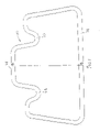
- FIG. 10 differs from that shown in FIG. 6 by the fact that the upper face 100 is also deformed in order to constitute a bulge 101 directed toward and in contact with the bulge 103 on the lower face 102 .
- a “butterfly” shape is produced, comprising two box sections 104 and 105 separated from each other.
- This “butterfly”-shaped profile has the advantage of providing two smaller volumes and of consequently increasing the resistance to the external pressure.
- the risk of buckling is reduced.
- the profile according to the invention shown in FIGS. 10 and 12 consists of a metal tube 1 which is bent so as to form the separate box sections 104 , 105 which are symmetrical with respect to a vertical axis of symmetry B-B.
- the box sections 104 , 105 are separated by an upper bulge 120 and a lower bulge 121 .
- the tube portion which constitutes the bottom of the lower bulge 121 lies approximately in the plane of the neutral fiber 17 and the upper bulge 120 bears on said tube portion, said portion forming a contact region 122 for the upper and lower walls of the tube after deformation.
- Each box section which preferably has a trapezoidal cross-section, has side walls 123 , 124 which are inclined and make an angle ⁇ greater than 60° and less than 90° with the horizontal C, which corresponds to a generatrix of the flexible pipe. Since the upper bulge 120 and lower bulge 121 are on the contact region 122 , which lies approximately on the plane of the neutral fiber 17 and therefore in an approximately central region of the profile, said region will therefore be subjected to few stresses during spiraling and will not work very much. This greatly improves the stability and the performance of the profile.
- the profile described above can be used for producing a pressure vault or the metal carcass, when the flexible pipe has one, by winding it in a helix, with a short pitch, about the horizontal axis A-A of the flexible pipe, each turn of the winding consisting of a pair of box sections. Since the profile is not self-interlockable, it is possible to interlock the turns in several ways.
- the first way of interlocking is shown in FIG. 10 .
- the turns of the winding of the profile are interlocked from below, that is to say the fasteners 12 ′, for example in the form of an inverted U, have their arms 13 ′ and 14 ′ placed in the consecutive lower bulges.
- Another interlocking is shown in FIG. 12 and it consists in using the same fasteners, but referenced 12 , which have their arms 13 and 14 placed in the consecutive upper bulges. In the latter case, interlocking is obtained from above, as opposed to the previous way which is called interlocking from below.
- Another method of interlocking consists in interlocking the turns from above and from below, with upper fasteners 12 whose arms 13 and 14 are placed in the upper bulges and lower fasteners 12 ′ whose arms 13 ′ and 14 ′ are placed in the lower bulges.
- the upper and/or lower fasteners may advantageously have, in the gap 125 between two consecutive turns, a bulge or hump, not shown, which makes it possible to increase the local moment of inertia of the fastener.
- the fastener stiffened at the hump, is more resistant to the internal pressure of the fluid flowing in the flexible pipe. Creep of the inner sealing sheath, owing to the effect of the internal pressure, applies a high contact pressure on the fastener.
- the radii of curvature of the hump correspond to those of the profile so as to allow the functional clearances of the vault to be maintained.
- the properties of the fastener Since the resistance to the internal pressure depends in part on the cross-section and on the mechanical properties of the material used, all that is required is to increase the thickness of the fastener or to choose a material having high mechanical properties, preferably properties superior to those of the profile; the vault-fastener pair will have a higher burst strength.
- means for reducing the creep of an impermeable inner polymeric sheath which bears on the profile may comprise, by themselves or in combination, a rod, which may be placed in the lower bulges, and/or a shaped wire, which covers the gap between two consecutive turns.
- the shaped wire may be flat or have the shape of an inverted T, the vertical arm of the T fitting into the gap.
- the shaped wire may also be an anticreep woven strip like that described in FR 2 744 511.
- These means for reducing the creep of a sheath may be provided above the profile when it is interlocked from below and when a polymeric sheath is placed above the profile. It should be noted that the rod may also be placed in the upper bulges.
- Another advantage lies in the fact that since the interlocking is carried out in the box section, the moment of inertia/pitch ratio of the profile is thus optimized while eliminating the regions of low moment of inertia.
- FIG. 11 relates to the special shape of a hollow profiled tube 110 whose upper wall 111 and lower wall 112 are deformed at two points with bulges 113 , 114 and 115 , 116 , respectively, the bulges 113 and 115 being in contact with each other while the bulges 114 and 116 are in contact with each other.
- Three separate box sections 117 , 118 and 119 are thus made.
- the depth of the bulges 113 to 116 depends essentially on the technical characteristics that it is desired to obtain.
- All the profiles shown in FIGS. 1 to 11 must not exceed a certain width L so that the hollow profiled tubes can be wound helically. This is because if the profile is too wide, during winding the forces will be too high and there would be a risk of them making the side walls of the profile buckle.
- the profile must therefore have a maximum width L which depends, on the one hand, on the thickness e of the tube and, on the other hand, on the height H of the profile. Tests carried out have shown that the results are satisfactory when: 0.5 ⁇ L/H ⁇ 5 and preferably 1 ⁇ L/H ⁇ 3 L/e ⁇ 20.
- the moment of inertia/weight ratio it was found that this was of about 1.6 with profiles of the present invention, which represents an increase of 20% compared with known lightened profiles and 60% compared with shaped wires.
- the present invention thus achieves two objectives, namely a reduced manufacturing cost and an increase in the moment of inertia/weight ratio for deep-sea use in which it is necessary to withstand high external pressures.
- an electrical conductor which can be used for possibly heating the fluid flowing in the flexible pipe, by the skin effect or by the Joule effect, by the induction effect, etc.
- the fastening may be effected from above the winding turns or from below, or else from above and from below, depending on the dynamic or static use of the flexible pipe.
- One advantage of interlocking from above and below is that it makes it possible to limit the creep of the internal and/or external plastic sheaths. It is also possible, when necessary, to fill the bulges with a filling material so as to limit the creep of said plastic sheaths.
- the present invention also relates to a process for manufacturing the flexible pipe, in which at least one of the metal reinforcing layers, such as the pressure vault or the metal carcass, is formed by a helical winding about the longitudinal axis of said flexible pipe of at least one interlocked hollow profiled tube having one of the cross-sections shown in FIGS. 1 to 11 .
- the cross-section of the hollow profiled tube is approximately trapezoidal.
Landscapes
- Engineering & Computer Science (AREA)
- General Engineering & Computer Science (AREA)
- Mechanical Engineering (AREA)
- Rigid Pipes And Flexible Pipes (AREA)
- Joints Allowing Movement (AREA)
- Materials For Medical Uses (AREA)
- Ultra Sonic Daignosis Equipment (AREA)
- Pipe Accessories (AREA)
- Supports For Pipes And Cables (AREA)
Applications Claiming Priority (5)
| Application Number | Priority Date | Filing Date | Title |
|---|---|---|---|
| FR0015203A FR2817318B1 (fr) | 2000-11-24 | 2000-11-24 | Conduite tubulaire flexible |
| FR00/15203 | 2000-11-24 | ||
| FR0101010A FR2819878B1 (fr) | 2000-11-24 | 2001-01-25 | Conduite tubulaire flexible |
| FR01/01010 | 2001-01-25 | ||
| PCT/FR2001/003525 WO2002042673A1 (fr) | 2000-11-24 | 2001-11-12 | Conduite tubulaire flexible |
Publications (2)
| Publication Number | Publication Date |
|---|---|
| US20040055657A1 US20040055657A1 (en) | 2004-03-25 |
| US7311123B2 true US7311123B2 (en) | 2007-12-25 |
Family
ID=26212745
Family Applications (2)
| Application Number | Title | Priority Date | Filing Date |
|---|---|---|---|
| US10/432,755 Expired - Fee Related US7311123B2 (en) | 2000-11-24 | 2001-11-12 | Flexible tubular pipe |
| US10/432,521 Expired - Lifetime US6840286B2 (en) | 2000-11-24 | 2001-11-12 | Flexible tubular pipe |
Family Applications After (1)
| Application Number | Title | Priority Date | Filing Date |
|---|---|---|---|
| US10/432,521 Expired - Lifetime US6840286B2 (en) | 2000-11-24 | 2001-11-12 | Flexible tubular pipe |
Country Status (9)
| Country | Link |
|---|---|
| US (2) | US7311123B2 (de) |
| EP (2) | EP1340013B1 (de) |
| AT (2) | ATE276472T1 (de) |
| AU (2) | AU2002223060A1 (de) |
| BR (2) | BR0115589B1 (de) |
| DE (2) | DE60105636D1 (de) |
| DK (2) | DK1340014T3 (de) |
| FR (2) | FR2817318B1 (de) |
| WO (2) | WO2002042674A1 (de) |
Cited By (16)
| Publication number | Priority date | Publication date | Assignee | Title |
|---|---|---|---|---|
| US20090159146A1 (en) * | 2007-12-21 | 2009-06-25 | Shawcor Ltd. | Styrenic insulation for pipe |
| US20100043906A1 (en) * | 2008-07-25 | 2010-02-25 | Shawcor Ltd. | High temperature resistant insulation for pipe |
| US20100059134A1 (en) * | 2006-12-22 | 2010-03-11 | Nkt Flexibiles I/S | Flexible pipe |
| US20100154916A1 (en) * | 2008-12-22 | 2010-06-24 | Shawcor Ltd. | Wrappable styrenic pipe insulations |
| WO2013071935A1 (en) * | 2011-11-15 | 2013-05-23 | National Oilwell Varco Denmark I/S | An unbonded flexible pipe |
| WO2013135244A1 (en) | 2012-03-13 | 2013-09-19 | National Oilwell Varco Denmark I/S | An unbonded flexible pipe with an optical fiber containing layer |
| US20140000748A1 (en) * | 2011-01-20 | 2014-01-02 | National Oilwell Varco Denmark I/S | Unbonded flexible pipe |
| US8960239B2 (en) | 2010-07-14 | 2015-02-24 | National Oilwell Varco Denmark I/S | Unbonded flexible pipe |
| US9012001B2 (en) | 2009-12-15 | 2015-04-21 | National Oilwell Varco Denmark I/S | Unbonded, flexible pipe |
| US9057465B2 (en) | 2009-12-28 | 2015-06-16 | National Oilwell Varco Denmark I/S | Unbonded, flexible pipe |
| US9395022B2 (en) | 2010-05-12 | 2016-07-19 | National Oilwell Varco Denmark I/S | Unbonded flexible pipe |
| US9458956B2 (en) | 2011-01-20 | 2016-10-04 | National Oilwell Varco Denmark I/S | Flexible armored pipe |
| US9562633B2 (en) | 2009-10-28 | 2017-02-07 | National Oilwell Varco Denmark I/S | Flexible pipe and a method of producing a flexible pipe |
| US9772053B2 (en) | 2012-09-03 | 2017-09-26 | National Oilwell Varco Denmark I/S | Unbonded flexible pipe |
| US9796148B2 (en) | 2012-04-12 | 2017-10-24 | National Oilwell Varco Denmark I/S | Method of producing an unbonded flexible pipe |
| US10113673B2 (en) | 2012-03-13 | 2018-10-30 | National Oilwell Varco Denmark I/S | Reinforcement element for an unbonded flexible pipe |
Families Citing this family (30)
| Publication number | Priority date | Publication date | Assignee | Title |
|---|---|---|---|---|
| DE69915515D1 (de) * | 1998-12-16 | 2004-04-15 | Nkt Flexibles I S Brondby | Armiertes, flexibles rohr und seine anwendung |
| US7518724B2 (en) * | 2000-07-11 | 2009-04-14 | Maven Technologies | Image acquisition, processing, and display |
| FR2817318B1 (fr) * | 2000-11-24 | 2002-12-27 | Coflexip | Conduite tubulaire flexible |
| US7923126B2 (en) | 2005-03-18 | 2011-04-12 | Nkt Flexibles I/S | Use of a steel composition for the production of an armouring layer of a flexible pipe and the flexible pipe |
| US8302634B2 (en) * | 2005-10-11 | 2012-11-06 | National Oilwell Varco Denmark I/S | Method of producing a flexible pipe and a flexible pipe |
| BRPI0720487B8 (pt) | 2006-12-22 | 2020-12-01 | Nat Oilwell Varco Denmark Is | tubo flexível |
| EP2126439B1 (de) | 2007-03-16 | 2014-06-11 | National Oilwell Varco Denmark I/S | Flexibles rohr |
| MX2009010230A (es) * | 2007-03-23 | 2009-11-23 | Nkt Flexibles Is | Un metodo para soldar cinta de acero inoxidable duplex para la produccion de una capa de armadura de un tubo flexible. |
| US20090041633A1 (en) * | 2007-05-14 | 2009-02-12 | Dultz Shane C | Apparatus and method for performing ligand binding assays on microarrays in multiwell plates |
| BRPI0815744A2 (pt) * | 2007-08-23 | 2015-02-18 | Nkt Flexibles Is | Tubo flexível. |
| GB2455285B (en) * | 2007-11-22 | 2012-05-09 | Schlumberger Holdings | Formation of flow conduits under pressure |
| US7981664B1 (en) | 2008-05-22 | 2011-07-19 | Maven Technologies, Llc | Apparatus and method for performing ligand binding assays on microarrays in multiwell plates |
| US8039270B2 (en) * | 2008-05-22 | 2011-10-18 | Maven Technologies, Llc | Apparatus and method for performing ligand binding assays on microarrays in multiwell plates |
| EP2228578A1 (de) | 2009-03-13 | 2010-09-15 | NV Bekaert SA | Edelstahldraht mit hohem Stickstoffgehalt für ein flexibles Rohr |
| AU2010305146B2 (en) | 2009-10-05 | 2015-02-05 | National Oilwell Varco Denmark I/S | A flexible unbonded oil pipe system with an optical fiber sensor inside |
| GB0922122D0 (en) | 2009-12-18 | 2010-02-03 | Wellstream Int Ltd | Flexible pipe having a carcass layer |
| GB0922120D0 (en) * | 2009-12-18 | 2010-02-03 | Wellstream Int Ltd | Flexible pipe including carcass layer |
| US8355133B2 (en) * | 2009-12-30 | 2013-01-15 | Maven Technologies, Llc | Biological testing with sawtooth-shaped prisms |
| DK201001031A (en) | 2010-11-12 | 2012-05-13 | Nat Oilwell Varco Denmark Is | A flexible pipe system |
| AU2012255186B2 (en) | 2011-05-13 | 2017-03-16 | National Oilwell Varco Denmark I/S | An unbonded flexible pipe and pipe system |
| US10001228B2 (en) | 2011-06-17 | 2018-06-19 | National Oilwell Varco Denmark I/S | Unbonded flexible pipe |
| US20130015287A1 (en) * | 2011-07-14 | 2013-01-17 | Bryant J Daniel | Spirally wound channel core |
| DK201100621A (en) | 2011-08-17 | 2013-02-18 | Nat Oilwell Varco Denmark Is | Armouring element for unbonded flexible pipe |
| US9580972B2 (en) | 2013-02-01 | 2017-02-28 | National Oilwell Varco Denmark I/S | Unbonded flexible armored riser pipe |
| GB201306665D0 (en) * | 2013-04-12 | 2013-05-29 | Wellstream Int Ltd | Elongate tape element and method |
| CN103629453B (zh) * | 2013-09-25 | 2016-02-10 | 中国海洋石油总公司 | 一种复合软管梯形截面互锁抗压铠装层 |
| FR3017438B1 (fr) * | 2014-02-11 | 2016-10-14 | Technip France | Conduite flexible de transport de fluide et procede associe |
| GB201611342D0 (en) * | 2016-06-30 | 2016-08-17 | Ge Oil & Gas Uk Ltd | Sacrificial shielding |
| GB201615346D0 (en) | 2016-09-09 | 2016-10-26 | Ge Oil & Gas Uk Ltd | Interlocked layer and method of manufacture |
| GB2621597A (en) * | 2022-08-16 | 2024-02-21 | Baker Hughes Energy Technology UK Ltd | Smoothing insert |
Citations (14)
| Publication number | Priority date | Publication date | Assignee | Title |
|---|---|---|---|---|
| US916890A (en) * | 1908-06-08 | 1909-03-30 | Ernest Rubes | Flexible metallic tubing. |
| US2022694A (en) * | 1929-05-07 | 1935-12-03 | Titeflex Metal Hose Co | Tube |
| US2402497A (en) * | 1943-04-12 | 1946-06-18 | Chicago Metal Hose Corp | Flexible tubing |
| US3311133A (en) * | 1964-01-22 | 1967-03-28 | Electri Flex Company | Flexible conduit |
| GB1081339A (en) | 1965-04-28 | 1967-08-31 | Angus George Co Ltd | Improvements in flexible ducting |
| US4368088A (en) | 1979-12-20 | 1983-01-11 | Toyo Kagaku Kabushiki Kaisha | Method of manufacturing corrugated tube |
| US4862924A (en) * | 1986-04-23 | 1989-09-05 | Shiro Kanao | Flexible hard pipe |
| FR2654795A1 (fr) | 1989-11-21 | 1991-05-24 | Coflexip | Conduite tubulaire flexible. |
| FR2665237A1 (fr) | 1990-07-27 | 1992-01-31 | Coflexip | Carcasse et conduite tubulaire flexible comportant une telle carcasse. |
| FR2782142A1 (fr) | 1998-08-10 | 2000-02-11 | Coflexip | Conduite flexible a enroulement de fil de forme en i |
| FR2784445A1 (fr) | 1998-10-12 | 2000-04-14 | Coflexip | Conduite flexible a frette de forte inertie |
| FR2808070A1 (fr) | 2000-04-21 | 2001-10-26 | Coflexip | Tube metallique flexible a caisson et conduite flexible comprenant un tel tube metallique |
| US6840286B2 (en) * | 2000-11-24 | 2005-01-11 | Coflexip | Flexible tubular pipe |
| US6904939B2 (en) * | 2001-10-24 | 2005-06-14 | Technip France | Flexible tubular pipe for hydrocarbon transport with carcass consisting of an elongated element stapled with a band iron |
Family Cites Families (5)
| Publication number | Priority date | Publication date | Assignee | Title |
|---|---|---|---|---|
| BE349393A (de) * | ||||
| EP0005175A1 (de) | 1978-04-20 | 1979-11-14 | Siemens Aktiengesellschaft | Wähltastatur |
| US4838317A (en) * | 1980-10-14 | 1989-06-13 | Andre James R | Hydraulically efficient ribbed pipe |
| DE19832822A1 (de) | 1998-07-21 | 2000-03-09 | Sterff Beteiligungsgesellschaf | Verfahren und Vorrichtung zur kapazitiven Demineralisierung von Ionen enthaltenden Flüssigkeiten |
| US6145546A (en) * | 1999-06-03 | 2000-11-14 | Coflexip | Flexible flowline for conveying fluids |
-
2000
- 2000-11-24 FR FR0015203A patent/FR2817318B1/fr not_active Expired - Fee Related
-
2001
- 2001-01-25 FR FR0101010A patent/FR2819878B1/fr not_active Expired - Fee Related
- 2001-11-12 DK DK01997657T patent/DK1340014T3/da active
- 2001-11-12 WO PCT/FR2001/003524 patent/WO2002042674A1/fr not_active Ceased
- 2001-11-12 US US10/432,755 patent/US7311123B2/en not_active Expired - Fee Related
- 2001-11-12 EP EP01997656A patent/EP1340013B1/de not_active Expired - Lifetime
- 2001-11-12 DK DK01997656T patent/DK1340013T3/da active
- 2001-11-12 US US10/432,521 patent/US6840286B2/en not_active Expired - Lifetime
- 2001-11-12 AU AU2002223060A patent/AU2002223060A1/en not_active Abandoned
- 2001-11-12 DE DE60105636T patent/DE60105636D1/de not_active Expired - Lifetime
- 2001-11-12 WO PCT/FR2001/003525 patent/WO2002042673A1/fr not_active Ceased
- 2001-11-12 AT AT01997656T patent/ATE276472T1/de not_active IP Right Cessation
- 2001-11-12 AU AU2002223059A patent/AU2002223059A1/en not_active Abandoned
- 2001-11-12 AT AT01997657T patent/ATE266832T1/de not_active IP Right Cessation
- 2001-11-12 DE DE60103303T patent/DE60103303D1/de not_active Expired - Lifetime
- 2001-11-12 BR BRPI0115589-0A patent/BR0115589B1/pt not_active IP Right Cessation
- 2001-11-12 BR BRPI0115588-1B1A patent/BR0115588B1/pt not_active IP Right Cessation
- 2001-11-12 EP EP01997657A patent/EP1340014B1/de not_active Expired - Lifetime
Patent Citations (16)
| Publication number | Priority date | Publication date | Assignee | Title |
|---|---|---|---|---|
| US916890A (en) * | 1908-06-08 | 1909-03-30 | Ernest Rubes | Flexible metallic tubing. |
| US2022694A (en) * | 1929-05-07 | 1935-12-03 | Titeflex Metal Hose Co | Tube |
| US2402497A (en) * | 1943-04-12 | 1946-06-18 | Chicago Metal Hose Corp | Flexible tubing |
| US3311133A (en) * | 1964-01-22 | 1967-03-28 | Electri Flex Company | Flexible conduit |
| GB1081339A (en) | 1965-04-28 | 1967-08-31 | Angus George Co Ltd | Improvements in flexible ducting |
| US4368088A (en) | 1979-12-20 | 1983-01-11 | Toyo Kagaku Kabushiki Kaisha | Method of manufacturing corrugated tube |
| US4862924A (en) * | 1986-04-23 | 1989-09-05 | Shiro Kanao | Flexible hard pipe |
| FR2654795A1 (fr) | 1989-11-21 | 1991-05-24 | Coflexip | Conduite tubulaire flexible. |
| FR2665237A1 (fr) | 1990-07-27 | 1992-01-31 | Coflexip | Carcasse et conduite tubulaire flexible comportant une telle carcasse. |
| US5669420A (en) * | 1990-07-27 | 1997-09-23 | Coflexip | Casing and flexible tubular conduit comprising such a casing and process for producing it |
| FR2782142A1 (fr) | 1998-08-10 | 2000-02-11 | Coflexip | Conduite flexible a enroulement de fil de forme en i |
| FR2784445A1 (fr) | 1998-10-12 | 2000-04-14 | Coflexip | Conduite flexible a frette de forte inertie |
| FR2808070A1 (fr) | 2000-04-21 | 2001-10-26 | Coflexip | Tube metallique flexible a caisson et conduite flexible comprenant un tel tube metallique |
| US6668867B2 (en) * | 2000-04-21 | 2003-12-30 | Institut Francais Du Petrole & Coflexip | Flexible metal tube with closed section and flexible pipe comprising same |
| US6840286B2 (en) * | 2000-11-24 | 2005-01-11 | Coflexip | Flexible tubular pipe |
| US6904939B2 (en) * | 2001-10-24 | 2005-06-14 | Technip France | Flexible tubular pipe for hydrocarbon transport with carcass consisting of an elongated element stapled with a band iron |
Cited By (22)
| Publication number | Priority date | Publication date | Assignee | Title |
|---|---|---|---|---|
| US8056585B2 (en) * | 2006-12-22 | 2011-11-15 | Nkt Flexibles I/S | Flexible pipe |
| US20100059134A1 (en) * | 2006-12-22 | 2010-03-11 | Nkt Flexibiles I/S | Flexible pipe |
| US8714206B2 (en) | 2007-12-21 | 2014-05-06 | Shawcor Ltd. | Styrenic insulation for pipe |
| US20090159146A1 (en) * | 2007-12-21 | 2009-06-25 | Shawcor Ltd. | Styrenic insulation for pipe |
| US8397765B2 (en) | 2008-07-25 | 2013-03-19 | Shawcor Ltd. | High temperature resistant insulation for pipe |
| US20100043906A1 (en) * | 2008-07-25 | 2010-02-25 | Shawcor Ltd. | High temperature resistant insulation for pipe |
| US8485229B2 (en) | 2008-12-22 | 2013-07-16 | Shawcor Ltd. | Wrappable styrenic pipe insulations |
| US20100154916A1 (en) * | 2008-12-22 | 2010-06-24 | Shawcor Ltd. | Wrappable styrenic pipe insulations |
| US9562633B2 (en) | 2009-10-28 | 2017-02-07 | National Oilwell Varco Denmark I/S | Flexible pipe and a method of producing a flexible pipe |
| US9012001B2 (en) | 2009-12-15 | 2015-04-21 | National Oilwell Varco Denmark I/S | Unbonded, flexible pipe |
| US9057465B2 (en) | 2009-12-28 | 2015-06-16 | National Oilwell Varco Denmark I/S | Unbonded, flexible pipe |
| US9395022B2 (en) | 2010-05-12 | 2016-07-19 | National Oilwell Varco Denmark I/S | Unbonded flexible pipe |
| US8960239B2 (en) | 2010-07-14 | 2015-02-24 | National Oilwell Varco Denmark I/S | Unbonded flexible pipe |
| US20140000748A1 (en) * | 2011-01-20 | 2014-01-02 | National Oilwell Varco Denmark I/S | Unbonded flexible pipe |
| US9188254B2 (en) * | 2011-01-20 | 2015-11-17 | National Oilwell Varco Denmark I/S | Unbonded flexible pipe |
| US9458956B2 (en) | 2011-01-20 | 2016-10-04 | National Oilwell Varco Denmark I/S | Flexible armored pipe |
| WO2013071935A1 (en) * | 2011-11-15 | 2013-05-23 | National Oilwell Varco Denmark I/S | An unbonded flexible pipe |
| WO2013135244A1 (en) | 2012-03-13 | 2013-09-19 | National Oilwell Varco Denmark I/S | An unbonded flexible pipe with an optical fiber containing layer |
| US9587773B2 (en) | 2012-03-13 | 2017-03-07 | National Oilwell Varco Denmark I/S | Unbonded flexible pipe with an optical fiber containing layer |
| US10113673B2 (en) | 2012-03-13 | 2018-10-30 | National Oilwell Varco Denmark I/S | Reinforcement element for an unbonded flexible pipe |
| US9796148B2 (en) | 2012-04-12 | 2017-10-24 | National Oilwell Varco Denmark I/S | Method of producing an unbonded flexible pipe |
| US9772053B2 (en) | 2012-09-03 | 2017-09-26 | National Oilwell Varco Denmark I/S | Unbonded flexible pipe |
Also Published As
| Publication number | Publication date |
|---|---|
| BR0115588A (pt) | 2003-09-23 |
| WO2002042674A1 (fr) | 2002-05-30 |
| DE60103303D1 (de) | 2004-06-17 |
| DK1340013T3 (da) | 2005-01-24 |
| BR0115588B1 (pt) | 2013-09-17 |
| FR2817318A1 (fr) | 2002-05-31 |
| US20040055657A1 (en) | 2004-03-25 |
| ATE276472T1 (de) | 2004-10-15 |
| DE60105636D1 (de) | 2004-10-21 |
| EP1340014A1 (de) | 2003-09-03 |
| US6840286B2 (en) | 2005-01-11 |
| EP1340013B1 (de) | 2004-09-15 |
| BR0115589B1 (pt) | 2011-11-01 |
| FR2819878B1 (fr) | 2003-02-28 |
| US20040074553A1 (en) | 2004-04-22 |
| AU2002223059A1 (en) | 2002-06-03 |
| EP1340013A1 (de) | 2003-09-03 |
| AU2002223060A1 (en) | 2002-06-03 |
| BR0115589A (pt) | 2003-09-16 |
| FR2817318B1 (fr) | 2002-12-27 |
| DK1340014T3 (da) | 2004-09-20 |
| WO2002042673A1 (fr) | 2002-05-30 |
| FR2819878A1 (fr) | 2002-07-26 |
| EP1340014B1 (de) | 2004-05-12 |
| ATE266832T1 (de) | 2004-05-15 |
Similar Documents
| Publication | Publication Date | Title |
|---|---|---|
| US7311123B2 (en) | Flexible tubular pipe | |
| US6668867B2 (en) | Flexible metal tube with closed section and flexible pipe comprising same | |
| AU722738B2 (en) | Flexible pipe with internal gasproof undulating metal tube | |
| US7004202B2 (en) | Composite strip windable to form a helical pipe and method therefor | |
| US7716803B2 (en) | Method for fabricating flexible pipe with armor tendons | |
| EP2079953B1 (de) | Verstärkter verbundstoffstreifen, der zur bildung eines schraubenförmigen rohrs aufwickelbar ist, und verfahren dafür | |
| US4403631A (en) | Flexible pipe | |
| US5595800A (en) | Helically wound reinforced ribbed composite structure | |
| AU661047B2 (en) | Helically wound reinforced ribbed composite structure | |
| KR920006736Y1 (ko) | 내압합성수지 나선관 | |
| NZ548765A (en) | Strip for helically wound pipe with base portion having upstanding ribs and reinforcing portion and lamina bonded to base of higher Young's modulus | |
| HK1130529B (en) | Composite reinforced strip windable to form a helical pipe and method therefor | |
| HK1074420B (en) | Composite strip windable to form a helical pipe and method thereof |
Legal Events
| Date | Code | Title | Description |
|---|---|---|---|
| AS | Assignment |
Owner name: COFLEXIP, FRANCE Free format text: ASSIGNMENT OF ASSIGNORS INTEREST;ASSIGNORS:ESPINASSE, PHILIPPE;JUNG, PATRICE JOEL LOUIS;AVERBUCH, DANIEL;AND OTHERS;REEL/FRAME:014577/0934;SIGNING DATES FROM 20030520 TO 20030523 Owner name: INSTITUT FRANCAIS DU PETROLE, FRANCE Free format text: ASSIGNMENT OF ASSIGNORS INTEREST;ASSIGNORS:ESPINASSE, PHILIPPE;JUNG, PATRICE JOEL LOUIS;AVERBUCH, DANIEL;AND OTHERS;REEL/FRAME:014577/0934;SIGNING DATES FROM 20030520 TO 20030523 |
|
| STCF | Information on status: patent grant |
Free format text: PATENTED CASE |
|
| FPAY | Fee payment |
Year of fee payment: 4 |
|
| FPAY | Fee payment |
Year of fee payment: 8 |
|
| FEPP | Fee payment procedure |
Free format text: MAINTENANCE FEE REMINDER MAILED (ORIGINAL EVENT CODE: REM.); ENTITY STATUS OF PATENT OWNER: LARGE ENTITY |
|
| LAPS | Lapse for failure to pay maintenance fees |
Free format text: PATENT EXPIRED FOR FAILURE TO PAY MAINTENANCE FEES (ORIGINAL EVENT CODE: EXP.); ENTITY STATUS OF PATENT OWNER: LARGE ENTITY |
|
| STCH | Information on status: patent discontinuation |
Free format text: PATENT EXPIRED DUE TO NONPAYMENT OF MAINTENANCE FEES UNDER 37 CFR 1.362 |
|
| FP | Lapsed due to failure to pay maintenance fee |
Effective date: 20191225 |