US7372414B2 - Apparatus for emission and/or reception of electromagnetic waves for aerodynes - Google Patents
Apparatus for emission and/or reception of electromagnetic waves for aerodynes Download PDFInfo
- Publication number
- US7372414B2 US7372414B2 US11/639,181 US63918106A US7372414B2 US 7372414 B2 US7372414 B2 US 7372414B2 US 63918106 A US63918106 A US 63918106A US 7372414 B2 US7372414 B2 US 7372414B2
- Authority
- US
- United States
- Prior art keywords
- reflect
- array
- antenna
- principal
- blade antenna
- Prior art date
- Legal status (The legal status is an assumption and is not a legal conclusion. Google has not performed a legal analysis and makes no representation as to the accuracy of the status listed.)
- Expired - Fee Related
Links
Images




Classifications
-
- H—ELECTRICITY
- H01—ELECTRIC ELEMENTS
- H01Q—ANTENNAS, i.e. RADIO AERIALS
- H01Q19/00—Combinations of primary active antenna elements and units with secondary devices, e.g. with quasi-optical devices, for giving the antenna a desired directional characteristic
- H01Q19/10—Combinations of primary active antenna elements and units with secondary devices, e.g. with quasi-optical devices, for giving the antenna a desired directional characteristic using reflecting surfaces
-
- H—ELECTRICITY
- H01—ELECTRIC ELEMENTS
- H01Q—ANTENNAS, i.e. RADIO AERIALS
- H01Q1/00—Details of, or arrangements associated with, antennas
- H01Q1/27—Adaptation for use in or on movable bodies
- H01Q1/28—Adaptation for use in or on aircraft, missiles, satellites, or balloons
- H01Q1/282—Modifying the aerodynamic properties of the vehicle, e.g. projecting type aerials
- H01Q1/283—Blade, stub antennas
-
- H—ELECTRICITY
- H01—ELECTRIC ELEMENTS
- H01Q—ANTENNAS, i.e. RADIO AERIALS
- H01Q1/00—Details of, or arrangements associated with, antennas
- H01Q1/27—Adaptation for use in or on movable bodies
- H01Q1/28—Adaptation for use in or on aircraft, missiles, satellites, or balloons
- H01Q1/286—Adaptation for use in or on aircraft, missiles, satellites, or balloons substantially flush mounted with the skin of the craft
- H01Q1/287—Adaptation for use in or on aircraft, missiles, satellites, or balloons substantially flush mounted with the skin of the craft integrated in a wing or a stabiliser
-
- H—ELECTRICITY
- H01—ELECTRIC ELEMENTS
- H01Q—ANTENNAS, i.e. RADIO AERIALS
- H01Q3/00—Arrangements for changing or varying the orientation or the shape of the directional pattern of the waves radiated from an antenna or antenna system
- H01Q3/44—Arrangements for changing or varying the orientation or the shape of the directional pattern of the waves radiated from an antenna or antenna system varying the electric or magnetic characteristics of reflecting, refracting, or diffracting devices associated with the radiating element
- H01Q3/46—Active lenses or reflecting arrays
Definitions
- This invention relates to an apparatus for emission and/or reception of electromagnetic waves for aerodynes. It is applicable for example in the aeronautics domain.
- IFE services create new constraints. For example, access to high speed Internet for each passenger requires very high transmission rates to geostationary satellites that distribute information.
- An additional emitting and/or receiving antenna has to be installed on the upper part of aircraft fuselages. Firstly, it must be possible to aim this antenna at any satellite, as a function of the geographic position of the aircraft that is continuously moving. Furthermore, the antenna must emit a high frequency wave adapted to high speed connection, for example in the X, Ku or Ka band, in other words at between 10 and 35 Gigahertz. Knowing that conventional communication and navigation functions alone require a large number of antennas distributed on the top and under the beneath of the aircraft, this creates problems with the available space and choice of installation zones, and problems in checking decoupling between antennas.
- This is the use of three classical fixed electronic scanning antennas arranged on the fuselage of the aircraft in three well-defined directions.
- a single antenna of this type has only a very limited angular coverage, covering a cone with an angle of the order of about 60° around the direction normal to the antenna.
- the signal loses quality when it is emitted at an angle far from the direction normal to the antenna. Therefore, three correctly oriented antennas are necessary to satisfy angular coverage constraints, with one being arranged horizontally above the fuselage and the other two arranged vertically on each side of the fuselage. But these antennas are relatively thick because they integrate a wave emission device behind the antenna itself, which is passed through by waves it refracts.
- This three antenna solution could be improved by the use of electronic scanning antennas of a known type referred to as ⁇ reflect-arrays>>.
- These antennas have the characteristic that they do not comprise a wave emission device integrated into the radiating array and consequently are very thin. These devices do not refract a wave generated behind the antenna, they reflect a wave generated in front of the antenna by an offset wave emission device.
- a reflect-array antenna adjusts the angle of reflection of the beam by a relative phase shift of the field radiated by elements arranged in array, using exactly the same principle as a classical electronic scanning antenna to adjust the refraction angle.
- the radiating elements arranged in array may be wave guides integrating diode phase shifters or Micro-Electro-Mechanical Systems, frequently called MEMS.
- This technology is well known from other applications.
- it is also necessary to install three masts with an aerodynamic profile fitted with illumination horns at their summit to illuminate the three reflect-arrays.
- This type of antenna has the same angular coverage limitations as classical electronic scanning antennas, namely about 60 degrees around the direction normal to the antenna, and once again three correctly oriented antennas are necessary to satisfy angular coverage constraints.
- One of them must be installed horizontally on the top of the fuselage with its illumination mast and the other two vertically on each side, also with their illumination masts. But even if the thickness is very low, the surface area required by such a solution is still too large.
- the main purpose of the invention is to overcome the disadvantages mentioned above by making good use of an existing structure on the aircraft fuselage, namely the blade type antenna.
- the purpose of the invention is an apparatus for emission and/or reception of electromagnetic waves for aerodynes comprising a blade antenna installed on the top of the fuselage of the aerodyne. It also comprises a principal reflect-array installed horizontally at the bottom of the blade antenna and a principal illumination horn located at the top of the blade antenna, the horn illuminating the principal reflect-array. It also comprises two secondary reflect-arrays arranged vertically on each side of the faces of the blade antenna and two secondary illumination horns arranged at the bottom of the antenna in the plane of the principal reflect-array, each horn illuminating one of the secondary reflect-arrays. Each reflect-array reflects waves emitted by the illuminating horn that illuminates it.
- one of the directional reflect-arrays may be an array of reflecting and directional radiating elements by relative phase shift of the field radiated by the elements, the array being sufficiently thin to not unduly increase the thickness of the blade antenna.
- the reflected waves are in the X, Ku or Ka band.
- the main advantages of the invention are that it is integrated on an existing support structure namely the blade antenna, without disturbing its operation.
- Conventional UHF and VHF radio voice communication functions of the blade antenna remain independent of the new functions on other frequency bands. Decoupling is achieved because these functions are applicable to very different frequency ranges. In particular, one can fail without having any influence on the other.
- it is a compact and modular multifunction solution that limits the increasing proliferation of antennas and facilitates maintenance. Not requiring any complex mechanical slaving device and making use of a technology based on electronic scanning; it is not only a more reliable solution but it is also a better solution in terms of precision and speed for pointing the beam.
- FIG. 1 is an illustration showing a side view of an example of embodiment of an apparatus according to the invention
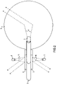
- FIG. 2 is an illustration showing a top view of the previous example of embodiment of an apparatus according to the invention.
- FIGS. 3 a and 3 b are illustrations showing side and front views of the angular coverage of the previous example of embodiment of an apparatus according to the invention.
- FIGS. 4 a and 4 b are illustrations showing top and front views of the angular coverage of the previous example of embodiment of an apparatus according to the invention.
- FIG. 1 and FIG. 2 illustrate the same example of embodiment of an apparatus according to the invention, FIG. 1 showing a side view and FIG. 2 showing a top view.
- a blade antenna 2 is installed vertically by its base on the top part of the fuselage 1 of an aircraft.
- a blade antenna is a conducting plate shaped like a blade. For example, it may be a quadrilateral in which two opposite sides forming the base and the top of the antenna are parallel, the length of its base being of the order of twice the length of its top.
- This blade shape has the twofold advantage of having an aerodynamic profile and being adapted to emission and reception of waves in the VHF and UHF bands used for radio voice communications between the pilot and traffic controllers on the ground. For example, it may be protected by a polyurethane cover.
- a reflect-array 3 is installed flat and horizontally on the fuselage of the aircraft at the bottom of the blade antenna 2 .
- An illumination horn 4 is arranged at the top of the blade antenna, for example at the back so as to be over the reflect-array 3 and oriented so as to illuminate it as efficiently as possible.
- a beam 9 of circular waves output from the illumination horn 4 in other words composed of spherical waves going in all directions, is reflected by the reflect-array 3 in a beam of plane waves, in other words composed of waves going in a single direction. This reflection direction depends on the relative phase shift of the field radiated by the elements of the reflect-array.
- this reflect-array technology cannot reflect a high quality signal outside a 60-degree cone centred on the normal direction to the reflect-array. Therefore, this antenna alone is not sufficient to cover a sufficiently large portion of space to hope to be able to aim at any geostationary satellite.
- two other reflect-arrays 5 and 6 are advantageously arranged flat and vertically on each side of the faces of the conducting plate forming the blade antenna.
- Two illumination horns 7 and 8 are arranged at the bottom of the blade antenna in the plane of the reflect-array 3 facing the reflect-arrays 5 and 6 and oriented so as to illuminate them as efficiently as possible.
- circular wave beams 10 and 11 output from the illumination horns 7 and 8 are reflected by the reflect-arrays 5 and 6 as plane wave beams.
- each of the two lateral reflect-array antennas has the same angular coverage limitation as the antenna at the bottom of the blade antenna, the total angular coverage of the assembly composed of the three reflect-array antennas is much wider.
- the emitted and reflected wave beams are in the X, Ku or Ka frequency band, in other words between 10 and 35 Gigahertz.
- FIGS. 3 a and 3 b illustrate the angular coverage of the reflect-array antenna 3 in the previous example of embodiment of an apparatus according to the invention.
- FIG. 3 a shows by a side view the angular coverage of the apparatus in a right cone with a 60-degrees half-opening whose axis is the direction 20 normal to the reflect-array 3 .
- FIG. 3 b shows by a front view the angular range of the apparatus in this cone. The entire portion of space above the aircraft is covered.
- FIGS. 4 a and 4 b illustrate the angular coverage of reflect-array antennas 5 and 6 in the previous example of embodiment of an apparatus according to the invention.
- FIG. 4 a is a top view showing firstly the angular range of the apparatus in a right cone with a 60-degree half-opening whose axis is the direction 21 normal to the reflect-array 5 , and secondly the angular range of the apparatus in a 60-degrees right cone whose axis is the normal 22 to the reflect-array 6 .
- FIG. 4 b shows a front view of the angular range of the apparatus in these two cones. The entire portion of space both at the right and at the left of the aircraft is covered.
- the apparatus according to the invention leaves only two shadow zones, one towards the front of the aircraft and the other towards the back.
- Each of these two shadow zones forms a right cone with a half-opening of about 30 degrees whose axis is longitudinal line to the aircraft.
- shadow zones often due to adjacent equipment.
- only satellites very far in front of or very far behind the aircraft will be inaccessible.
- the apparatus according to the invention is quite suitable for transmission of IFE system information. Furthermore, the apparatus according to the invention has a major economic advantage because it does not introduce maintenance difficulties, reliability problems or additional consumption compared with existing solutions based on mechanical slaving or classical electronic scanning.
Landscapes
- Physics & Mathematics (AREA)
- Engineering & Computer Science (AREA)
- Remote Sensing (AREA)
- Astronomy & Astrophysics (AREA)
- Aviation & Aerospace Engineering (AREA)
- General Physics & Mathematics (AREA)
- Fluid Mechanics (AREA)
- Variable-Direction Aerials And Aerial Arrays (AREA)
- Aerials With Secondary Devices (AREA)
- Details Of Aerials (AREA)
- Circuits Of Receivers In General (AREA)
- Control Of High-Frequency Heating Circuits (AREA)
- Burglar Alarm Systems (AREA)
Applications Claiming Priority (2)
| Application Number | Priority Date | Filing Date | Title |
|---|---|---|---|
| FR0512846 | 2005-12-16 | ||
| FR0512846A FR2895152B1 (fr) | 2005-12-16 | 2005-12-16 | Dispositif d'emission et/ou de reception d'ondes electromagnetiques pour aerodynes |
Publications (2)
| Publication Number | Publication Date |
|---|---|
| US20070216586A1 US20070216586A1 (en) | 2007-09-20 |
| US7372414B2 true US7372414B2 (en) | 2008-05-13 |
Family
ID=36072115
Family Applications (1)
| Application Number | Title | Priority Date | Filing Date |
|---|---|---|---|
| US11/639,181 Expired - Fee Related US7372414B2 (en) | 2005-12-16 | 2006-12-15 | Apparatus for emission and/or reception of electromagnetic waves for aerodynes |
Country Status (5)
| Country | Link |
|---|---|
| US (1) | US7372414B2 (de) |
| EP (1) | EP1798809B1 (de) |
| AT (1) | ATE405002T1 (de) |
| DE (1) | DE602006002230D1 (de) |
| FR (1) | FR2895152B1 (de) |
Cited By (3)
| Publication number | Priority date | Publication date | Assignee | Title |
|---|---|---|---|---|
| US9300040B2 (en) | 2008-07-18 | 2016-03-29 | Phasor Solutions Ltd. | Phased array antenna and a method of operating a phased array antenna |
| US9628125B2 (en) | 2012-08-24 | 2017-04-18 | Phasor Solutions Limited | Processing a noisy analogue signal |
| US9917714B2 (en) | 2014-02-27 | 2018-03-13 | Phasor Solutions Limited | Apparatus comprising an antenna array |
Families Citing this family (4)
| Publication number | Priority date | Publication date | Assignee | Title |
|---|---|---|---|---|
| US9059508B2 (en) * | 2012-10-09 | 2015-06-16 | The Boeing Company | Conformal active reflect array for co-site and multi-path interference reduction |
| US10170843B2 (en) | 2015-05-29 | 2019-01-01 | California Institute Of Technology | Parabolic deployable antenna |
| US20170110803A1 (en) * | 2015-07-08 | 2017-04-20 | California Institute Of Technology | Deployable reflectarray high gain antenna for satellite applications |
| US11677140B2 (en) * | 2020-09-15 | 2023-06-13 | Gilat Satellite Networks Ltd. | Controllable antenna arrays for wireless communications |
Citations (8)
| Publication number | Priority date | Publication date | Assignee | Title |
|---|---|---|---|---|
| US4148040A (en) | 1976-11-03 | 1979-04-03 | The Boeing Company | High resolution side-looking airborne radar antenna |
| US4931808A (en) * | 1989-01-10 | 1990-06-05 | Ball Corporation | Embedded surface wave antenna |
| USH1219H (en) * | 1991-04-19 | 1993-08-03 | The United States Of America As Represented By The Secretary Of The Navy | Electrically small cavity antenna |
| US5359338A (en) * | 1989-09-20 | 1994-10-25 | The Boeing Company | Linear conformal antenna array for scanning near end-fire in one direction |
| EP0829918A2 (de) | 1996-09-12 | 1998-03-18 | Trw Inc. | Multifunktionelles, in die Struktur integriertes Flugzeugantennensystem für VHF-UHF |
| US5982339A (en) * | 1996-11-26 | 1999-11-09 | Ball Aerospace & Technologies Corp. | Antenna system utilizing a frequency selective surface |
| US6208304B1 (en) | 1999-05-10 | 2001-03-27 | Ems Technologies Canada, Ltd. | Aircraft mounted dual blade antenna array |
| WO2003058753A2 (en) | 2001-12-21 | 2003-07-17 | The Boeing Company | Structurally-integrated, space-fed phased array antenna system for use on an aircraft |
-
2005
- 2005-12-16 FR FR0512846A patent/FR2895152B1/fr not_active Expired - Fee Related
-
2006
- 2006-12-08 EP EP06125691A patent/EP1798809B1/de not_active Not-in-force
- 2006-12-08 DE DE602006002230T patent/DE602006002230D1/de active Active
- 2006-12-08 AT AT06125691T patent/ATE405002T1/de not_active IP Right Cessation
- 2006-12-15 US US11/639,181 patent/US7372414B2/en not_active Expired - Fee Related
Patent Citations (9)
| Publication number | Priority date | Publication date | Assignee | Title |
|---|---|---|---|---|
| US4148040A (en) | 1976-11-03 | 1979-04-03 | The Boeing Company | High resolution side-looking airborne radar antenna |
| US4931808A (en) * | 1989-01-10 | 1990-06-05 | Ball Corporation | Embedded surface wave antenna |
| US5359338A (en) * | 1989-09-20 | 1994-10-25 | The Boeing Company | Linear conformal antenna array for scanning near end-fire in one direction |
| USH1219H (en) * | 1991-04-19 | 1993-08-03 | The United States Of America As Represented By The Secretary Of The Navy | Electrically small cavity antenna |
| EP0829918A2 (de) | 1996-09-12 | 1998-03-18 | Trw Inc. | Multifunktionelles, in die Struktur integriertes Flugzeugantennensystem für VHF-UHF |
| US5982339A (en) * | 1996-11-26 | 1999-11-09 | Ball Aerospace & Technologies Corp. | Antenna system utilizing a frequency selective surface |
| US6208304B1 (en) | 1999-05-10 | 2001-03-27 | Ems Technologies Canada, Ltd. | Aircraft mounted dual blade antenna array |
| WO2003058753A2 (en) | 2001-12-21 | 2003-07-17 | The Boeing Company | Structurally-integrated, space-fed phased array antenna system for use on an aircraft |
| US6714163B2 (en) * | 2001-12-21 | 2004-03-30 | The Boeing Company | Structurally-integrated, space-fed phased array antenna system for use on an aircraft |
Cited By (5)
| Publication number | Priority date | Publication date | Assignee | Title |
|---|---|---|---|---|
| US9300040B2 (en) | 2008-07-18 | 2016-03-29 | Phasor Solutions Ltd. | Phased array antenna and a method of operating a phased array antenna |
| US10008772B2 (en) | 2008-07-18 | 2018-06-26 | Phasor Solutions Limited | Phased array antenna and a method of operating a phased array antenna |
| US9628125B2 (en) | 2012-08-24 | 2017-04-18 | Phasor Solutions Limited | Processing a noisy analogue signal |
| US10069526B2 (en) | 2012-08-24 | 2018-09-04 | Phasor Solutions Limited | Processing a noisy analogue signal |
| US9917714B2 (en) | 2014-02-27 | 2018-03-13 | Phasor Solutions Limited | Apparatus comprising an antenna array |
Also Published As
| Publication number | Publication date |
|---|---|
| EP1798809A1 (de) | 2007-06-20 |
| EP1798809B1 (de) | 2008-08-13 |
| DE602006002230D1 (de) | 2008-09-25 |
| FR2895152B1 (fr) | 2008-01-25 |
| FR2895152A1 (fr) | 2007-06-22 |
| ATE405002T1 (de) | 2008-08-15 |
| US20070216586A1 (en) | 2007-09-20 |
Similar Documents
| Publication | Publication Date | Title |
|---|---|---|
| US10938105B2 (en) | Conformal multi-band antenna structure | |
| EP1730811B1 (de) | Antenne mit teilweise sphärischen dielektrischen linsen | |
| US8749446B2 (en) | Wide-band linked-ring antenna element for phased arrays | |
| EP0907983B1 (de) | Planare gruppenantenne für zwei frequenzen | |
| AU736065B2 (en) | A terminal and antenna system for constellation of non- geostationary satellites | |
| KR20020042820A (ko) | 이동 플랫폼용 낮은 높이, 저가, 고이득 안테나 및 시스템 | |
| GB2542163A (en) | Lightweight process and apparatus for communicating with a user antenna phased arrays | |
| US9377529B2 (en) | On-board meteorological radar having a rotating antenna | |
| US5543815A (en) | Shielding screen for integration of multiple antennas | |
| US7372414B2 (en) | Apparatus for emission and/or reception of electromagnetic waves for aerodynes | |
| CN112335122B (zh) | 带有模块化辐射元件的天线 | |
| CA1205184A (en) | Dual-band antenna system of a beam waveguide type | |
| US10734716B2 (en) | Broadband unmanned aerial vehicle (UAV) patch antenna | |
| CN114421117B (zh) | 一种星载多频段一体化接收天线 | |
| US7688268B1 (en) | Multi-band antenna system | |
| US7605770B2 (en) | Flap antenna and communications system | |
| US12034211B2 (en) | Array antenna | |
| US20220037798A1 (en) | Lens integrated planar programmable polarized and beamsteering antenna array | |
| JPH03139926A (ja) | 宇宙アンテナ・システム | |
| RU2408140C2 (ru) | Антенно-электронный блок с управляемой конфигурацией диаграммы направленности | |
| KR102201572B1 (ko) | 빔패턴 조절 및 널(Null) 개선이 가능한 3차원 리플렉터를 포함하는 차량용 안테나 | |
| Gregorwich | Conformal airborne arrays | |
| CN107919536B (zh) | 用于卫星通信的双线极化天线馈源阵列及卫星通信天线 | |
| McLain et al. | Antennas for Aeronautical Broadband Services | |
| Moslemi | Design, fabrication, and test of a radiating element for a KU-BAND smart antenna |
Legal Events
| Date | Code | Title | Description |
|---|---|---|---|
| AS | Assignment |
Owner name: THALES, FRANCE Free format text: ASSIGNMENT OF ASSIGNORS INTEREST;ASSIGNORS:SOIRON, MICHEL;GUILLAUMOT, GEORGES;DOUSSET, THIERRY;REEL/FRAME:018846/0062 Effective date: 20070119 |
|
| STCF | Information on status: patent grant |
Free format text: PATENTED CASE |
|
| FPAY | Fee payment |
Year of fee payment: 4 |
|
| FPAY | Fee payment |
Year of fee payment: 8 |
|
| FEPP | Fee payment procedure |
Free format text: MAINTENANCE FEE REMINDER MAILED (ORIGINAL EVENT CODE: REM.); ENTITY STATUS OF PATENT OWNER: LARGE ENTITY |
|
| LAPS | Lapse for failure to pay maintenance fees |
Free format text: PATENT EXPIRED FOR FAILURE TO PAY MAINTENANCE FEES (ORIGINAL EVENT CODE: EXP.); ENTITY STATUS OF PATENT OWNER: LARGE ENTITY |
|
| STCH | Information on status: patent discontinuation |
Free format text: PATENT EXPIRED DUE TO NONPAYMENT OF MAINTENANCE FEES UNDER 37 CFR 1.362 |
|
| FP | Lapsed due to failure to pay maintenance fee |
Effective date: 20200513 |