US7395721B2 - Force sensor, force detection system and force detection program - Google Patents
Force sensor, force detection system and force detection program Download PDFInfo
- Publication number
- US7395721B2 US7395721B2 US11/020,415 US2041504A US7395721B2 US 7395721 B2 US7395721 B2 US 7395721B2 US 2041504 A US2041504 A US 2041504A US 7395721 B2 US7395721 B2 US 7395721B2
- Authority
- US
- United States
- Prior art keywords
- output
- force
- sensor
- unit
- displacement
- Prior art date
- Legal status (The legal status is an assumption and is not a legal conclusion. Google has not performed a legal analysis and makes no representation as to the accuracy of the status listed.)
- Expired - Fee Related
Links
Images


Classifications
-
- G—PHYSICS
- G01—MEASURING; TESTING
- G01L—MEASURING FORCE, STRESS, TORQUE, WORK, MECHANICAL POWER, MECHANICAL EFFICIENCY, OR FLUID PRESSURE
- G01L1/00—Measuring force or stress, in general
- G01L1/14—Measuring force or stress, in general by measuring variations in capacitance or inductance of electrical elements, e.g. by measuring variations of frequency of electrical oscillators
- G01L1/142—Measuring force or stress, in general by measuring variations in capacitance or inductance of electrical elements, e.g. by measuring variations of frequency of electrical oscillators using capacitors
-
- G—PHYSICS
- G01—MEASURING; TESTING
- G01L—MEASURING FORCE, STRESS, TORQUE, WORK, MECHANICAL POWER, MECHANICAL EFFICIENCY, OR FLUID PRESSURE
- G01L5/00—Apparatus for, or methods of, measuring force, work, mechanical power, or torque, specially adapted for specific purposes
- G01L5/16—Apparatus for, or methods of, measuring force, work, mechanical power, or torque, specially adapted for specific purposes for measuring several components of force
- G01L5/165—Apparatus for, or methods of, measuring force, work, mechanical power, or torque, specially adapted for specific purposes for measuring several components of force using variations in capacitance
-
- G—PHYSICS
- G06—COMPUTING OR CALCULATING; COUNTING
- G06F—ELECTRIC DIGITAL DATA PROCESSING
- G06F3/00—Input arrangements for transferring data to be processed into a form capable of being handled by the computer; Output arrangements for transferring data from processing unit to output unit, e.g. interface arrangements
- G06F3/01—Input arrangements or combined input and output arrangements for interaction between user and computer
- G06F3/03—Arrangements for converting the position or the displacement of a member into a coded form
- G06F3/033—Pointing devices displaced or positioned by the user, e.g. mice, trackballs, pens or joysticks; Accessories therefor
- G06F3/0338—Pointing devices displaced or positioned by the user, e.g. mice, trackballs, pens or joysticks; Accessories therefor with detection of limited linear or angular displacement of an operating part of the device from a neutral position, e.g. isotonic or isometric joysticks
-
- H—ELECTRICITY
- H03—ELECTRONIC CIRCUITRY
- H03K—PULSE TECHNIQUE
- H03K17/00—Electronic switching or gating, i.e. not by contact-making and –breaking
- H03K17/94—Electronic switching or gating, i.e. not by contact-making and –breaking characterised by the way in which the control signals are generated
- H03K17/96—Touch switches
- H03K17/9625—Touch switches using a force resistance transducer
-
- H—ELECTRICITY
- H01—ELECTRIC ELEMENTS
- H01H—ELECTRIC SWITCHES; RELAYS; SELECTORS; EMERGENCY PROTECTIVE DEVICES
- H01H25/00—Switches with compound movement of handle or other operating part
- H01H25/002—Switches with compound movement of handle or other operating part having an operating member rectilinearly slidable in different directions
- H01H2025/004—Switches with compound movement of handle or other operating part having an operating member rectilinearly slidable in different directions the operating member being depressable perpendicular to the other directions
-
- H—ELECTRICITY
- H01—ELECTRIC ELEMENTS
- H01H—ELECTRIC SWITCHES; RELAYS; SELECTORS; EMERGENCY PROTECTIVE DEVICES
- H01H2239/00—Miscellaneous
- H01H2239/006—Containing a capacitive switch or usable as such
-
- H—ELECTRICITY
- H01—ELECTRIC ELEMENTS
- H01H—ELECTRIC SWITCHES; RELAYS; SELECTORS; EMERGENCY PROTECTIVE DEVICES
- H01H25/00—Switches with compound movement of handle or other operating part
- H01H25/04—Operating part movable angularly in more than one plane, e.g. joystick
- H01H25/041—Operating part movable angularly in more than one plane, e.g. joystick having a generally flat operating member depressible at different locations to operate different controls
Definitions
- the invention relates to a force sensor that converts forces to electrical information such as capacitance and the like, in particular, to a force sensor, a force detection system and a force detection program used for conversion of manual inputs and the like into electrical signals.
- the sensor for converting a force to capacitance is typically used for a bathroom scale and the like.
- This type of force sensor typically has an operation input unit constituted as a button type or a stick type to serve as a man-machine interface and is used, for example, as a stick type input device of a notebook type personal computer.
- FIG. 1 and FIG. 2 show the outline of a general force sensor of the prior art, wherein FIG. 1(A) shows its plan view, FIG. 1(B) shows its IB-IB cross section, FIG. 1(C) shows its detection electrode, FIG. 2(A) shows its plan view, FIG. 2(B) shows its IIB-IIB cross section, and FIG. 2(C) shows its detection electrode.
- a force sensor 2 has a structure 6 consisting of insulators such as silicon rubber and conductors provided on a substrate 4 , as well as an electrode 8 on the ceiling of the structure 6 and a detection electrode 10 facing the electrode 8 on the side of the substrate 4 . If the electrode is made of the conductor of the structure 6 , it is not necessary to provide the electrode 8 independently.
- the device shown in FIG. 1 has a structure 6 formed as a beam supported on both ends and a circular detection electrode 10
- the device shown in FIG. 2 has a structure 6 formed as a cantilever beam and a rectangular detection electrode 10 .
- JP-A-6-314163 A sensor that provides the change of capacitance C as an output relative to the force “f” applied is disclosed by JP-A-6-314163.
- a capacitance type sensor disclosed in said document has a substantial displacement of the input part, and is constituted with two substantial substrates provided in parallel positions to allow them to move in parallel to each other, where electrodes are provided on their opposing surfaces respectively and positioned at 90° angles to each other.
- the reliability of the input-output relation is critical in case of such a force sensor, in particular, the stability of said zero point output (offset output) is extremely important. Therefore, it is necessary for the output to be zero or present a specific offset value and the value is constant when it is not operated. In other words, the reliability of the detection device will be lost if the output varies or the offset value varies when it is not operated, making it impossible to determine the zero point.
- a pointing device using a force sensor may cause such a problem that a minute output signal causes to move the pointer when the zero point or the offset value changes when there is no operation. For example, a case has been reported that a pointer started to move by merely receiving air from an air conditioner unit entirely unrelated to the user's intention.
- the input/output relation of the force sensor requires that there is a certain relation between input and output, it is extremely difficult to distinguish the output drift due to the environmental change and the output change due to a minute input when a minute force is to be detected under a condition where there are output drift due to changes in environmental factors such as temperature. Trying to stabilize the output against changes in environmental factors such as temperature tends to be expensive.
- a problem with the use of an involatile memory device for storing the zero point value at the time of a factory shipment is that it means an additional cost.
- the zero point value at the time of storage can be affected by changes of environmental factors such as temperature and humidity, so that it is impossible to follow such zero point fluctuations.
- FIG. 5(A) Let us describe the method of zero point setting of the force sensor ( FIG. 1 or FIG. 2 ) referring to FIG. 5 .
- FIG. 5(A) five inputs f 1 , f 2 , f 3 , f 4 , and f 5 are entered within a short spun of time, wherein the size relation between the inputs f 1 through f 5 is f 2 >f 1 >f 3 ⁇ f 4 ⁇ f 5 , i.e., f 2 has the highest level, while f 1 and f 2 have the longest time span, and f 3 , f 4 and f 5 are minute inputs of minute time spans. Moreover, it is assumed that minute inputs are entered after a gigantic input.
- a force sensor 2 For such inputs f 1 through f 5 , a force sensor 2 generates outputs C 11 , C 12 , C 13 , C 14 and C 15 in correspondence with the inputs as shown in FIG. 5(B) , i.e., showing changes of capacitance in correspondence with the input, a minute output is generated in the b 1 section after the output C 11 for the first input f 1 despite the fact that there is no input. This is the residual output. Moreover, a large residual output is generated in the b 2 section immediately after the output C 12 due to the input f 2 . Since the outputs C 13 through C 15 are overlapping on said residual output and the inputs are smaller after b 3 , it is understandable that the residual output reduces with time.
- FIG. 5(D) shows the outputs C 110 , C 120 , C 130 , C 140 , (C 150 ) that have levels lowered as a result of compensations due to the dead zone region setup.
- the delay time td will be generated between the input and the output, thus deteriorating the time-related response.
- the minute output C 15 can become buried into the dead zone level and may not generate any output (“d” section), thus deteriorating the level-related response.
- the forced zero point setup according to the dead zone region setup may deteriorate the detection sensitivity and the input relation and affect the reliability of the force sensor.
- the present invention relates to a force sensor that converts a force into capacitance and is intended to provide a force sensor that makes it possible to generate a plurality of outputs with different output characteristics.
- the present invention also relates to the output processing of a force sensor that converts a force into capacitance to make it possible to obtain a plurality of outputs from a single input and to use other outputs as reference information for obtaining an output in order to increase the output accuracy.
- the present invention is equipped with a plurality of sensor units on a common displacement unit so that it obtains an output from each sensor unit individually with referring to other outputs, thus making it possible to eliminate the offset of the displacement unit and to set up the zero point, so that it can improve the output accuracy.
- the force sensor of the present invention has a displacement unit that displaces when a force is applied, a single or a plurality of first sensor units that generates a first output from the displacement of said displacement unit, and a second sensor unit that is annexed to said first sensor unit and generates a second output from the displacement of said displacement unit.
- the first and second sensor units will provide the first and second independent outputs from the displacement generated by an applied force. These two outputs can be used as reference information as complimentary or compensative data to each other.
- the first and second sensor units can both consist of either a single or plural sensors.
- the force sensor can be constituted in such a way as the displacement of said displacement unit includes either a deformation of said displacement unit or a movement of said displacement unit by force or both thereof.
- the force sensor can be constituted in such a way as the output of said second sensor unit rises steeply from the output of said first sensor unit and shifts to a saturated state ahead of the output of said first sensor unit.
- the second output can be used as input information, for example, to indicate that a force is applied to the displacement unit.
- Said output can be used as the zero point information of the first output.
- the force sensor can be constituted in such a way as said second sensor is provided in the center of said displacement unit, while said first sensor unit is provided to surround said second sensor.
- the force detection system of the present system has a force sensor equipped with first and second sensor units in a displacement unit that displaces when a force is applied and generates first and second outputs that represent the displacement of said displace unit, and a processing unit that obtains said first output using said second output of said force sensor as the reference information for said first output.
- the displacement unit is equipped with the first and second sensors, so that it generates a displacement when subjected to a force and is possible to generate the first output from the first sensor unit and the second output from the second sensor unit independently. While each output can be used independently, they have a relation of being mechanically and simultaneously generated because they share a common displacement unit. Therefore, it is possible to use the second output as reference data in generating the first output. For example, if it is used as the time information or the level information, it is possible to conduct a process of generating the first output within the time the second output is generated referencing the time the second output is generated, or generating the first output if the second output's level exceeds a specified value. With such a constitution, the reliability of the first output can be enhanced using the correlation between the first and second outputs.
- the force detection system can also be constituted in such a way as said processing unit extracts time information representing level periods that exceed a specified level from said second output and obtains said first output referencing said time information.
- the force detection system can also be constituted in such a way as said second sensor unit of said force sensor shifts said second output to a saturated condition soon after said displacement unit starts to displace.
- the system can be constituted in such a way that the second output saturates soon after the displacement of the displacement unit if the second output is to be used as the reference information of the first output.
- the force detection system can also be constituted in such a way as said reference information is zero point information of said first output.
- said reference information is zero point information of said first output.
- the force detection program of the invention is constituted to include a function of obtaining a first output from a first sensor unit provided in a displacement unit that displaces when a force is applied, a function of obtaining a second output from a second sensor unit provided in said displacement unit, a function of extracting time information representing a level period that exceeds a specified level from said second output, and a function of obtaining said first output referencing said time information.
- the present invention provides the following effects.
- the force sensor of the present invention it is possible to provide a force sensor of a high reliability with a highly accurate sensor output, as it is possible to obtain a plurality of outputs from a common displacement unit independently, referencing other outputs for obtaining one output, and using them as reference information for the purpose of compensating offset outputs between various outputs, etc.
- the force detection system or the force detection program of the present invention it is possible to compensate the first output using the second output as the reference information of the first output, thus to achieve a force detection with a high reliability by compensating for fluctuations of the force censor and output errors due to characteristic values of the material used in the displacement unit.
- FIG. 1 is a diagram showing a force sensor of the prior art.
- FIG. 2 is a diagram showing another force sensor of the prior art.
- FIG. 3 shows a diagram showing the deformation status of a force sensor in response to an input force.
- FIG. 4 is a graph showing the input/output relation.
- FIG. 5 is a graph showing the input/output relation.
- FIG. 6 is a diagram showing a first embodiment of the present invention.
- FIG. 7 is a diagram showing the deformation of a force sensor according to the first embodiment.
- FIG. 8 is a diagram showing the input/output relation of a first sensor unit.
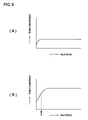
- FIG. 9 is a diagram showing the input/output relation of a second sensor unit.
- FIG. 10 is a block diagram showing a second embodiment of the present invention.
- FIG. 11 is a flowchart showing a third embodiment of the present invention.
- FIG. 12 is a diagram showing the input/output relations of the first and second sensor units.
- FIG. 13 is diagram showing a fourth embodiment of the present invention.
- FIG. 14 is a cross section showing a fifth embodiment of the present invention.
- FIG. 15 is a diagram showing the input/output relations of the first and second sensor units.
- FIG. 16 is diagram showing a sixth embodiment of the present invention.
- FIG. 17 is a diagram showing the input/output relations of the first and second sensor units.
- FIG. 18 is a block diagram showing a seventh embodiment of the present invention.
- FIG. 19 is diagram showing a eighth embodiment of the present invention.
- FIG. 20 is a block diagram showing a ninth embodiment of the present invention.
- FIG. 21 is a block diagram showing a tenth embodiment of the present invention.
- FIG. 22 is a block diagram showing an eleventh embodiment of the present invention.
- FIG. 23 is a diagram showing the detection operation of a force sensor according to the eleventh embodiment.
- FIG. 24 is a diagram showing the input/output relations of the first and second sensor units.
- FIG. 25 is a plan view showing a variation of the detection electrode.
- FIG. 26 is a plan view showing a variation of the detection electrode.
- FIG. 27 is a cross section showing variation of the second sensor unit.
- FIG. 6 shows a force sensor, wherein (A) is its plan view, (B) is a cross section along the VIB-VIB line of (A), and (C) is a plan view of the force sensor showing it without the displacement unit.
- This force sensor 20 is equipped with a displacement part 24 , which is mounted on a substrate 22 , for generating a displacement when an external force is applied, the displacement part 24 is equipped with a cylindrical support part 26 , which is flexible in the vertical direction in this embodiment, an tabular input part 28 integrally formed with the support part 26 , and a columnar protrusion 30 in the inner center of the input part 28 .
- the displacement part 24 is made of an elastic material such as rubber or metallic so that it can deform when an external force is applied and restore its original form when the force is removed.
- An annular shaped detection electrode 32 is mounted on the substrate 22 as a first detection electrode, while an electrode 34 with a shape identical to the detection electrode 32 is provided on the inner surface of the input part 28 facing the detection electrode 32 .
- the detection electrode 32 and the electrode 34 constitute a first sensor unit 36 .
- the sensor unit 36 is constituted in such a way that, assuming the opposing area S 1 of the detection electrode 32 and the electrode 34 is constant, it generate capacitance C 1 in response to a force f as the electrode distance d 1 changes under the force f.
- the detection electrode 32 and the electrode 34 are assumed to be annular, they can be rectangular as well.
- a circular detection electrode 40 is provided as a second detection electrode inside the detection electrode 32 separated by an insulation distance 38 .
- An electrode 42 is provided on the tip of the protrusion 30 to face the detection electrode 40 .
- the detection electrode 40 and the electrode 42 constitute a second sensor unit 44 .
- the sensor unit 44 is constituted in such a way that, assuming the opposing area S 2 of the detection electrode 40 and the electrode 42 is constant, it generate capacitance C 2 in response to a force f as the electrode distance d 2 changes under the force f.
- the electrode distance d 2 for the sensor 44 is smaller than the electrode distance d 1 for the sensor 36 by the length of the protrusion 30 (d 1 >d 2 ).
- the detection electrode 40 and the electrode 42 are assumed to be circular, they can be rectangular as well.
- the displacement part 24 deforms corresponding to the force f and the input part 28 , as well as the support part 26 , bends as shown in FIG. 7 , causing the detection electrode 32 to approach the electrode 34 while the electrode 42 of the protrusion 30 to approach the detection electrode 40 until finally making a contact.
- the electrode 42 makes a contact with the detection electrode 40 soon after the input part 28 starts a displacement.
- Such a displacement causes the sensor unit 36 to generate capacitance C 1 in accordance with the facing area S 1 and the electrode distance d 1 and the sensor unit 44 to generate capacitance C 2 as the output of the second sensor in accordance with the facing area S 2 and the electrode distance d 2 .
- the input/output relation of the sensor unit 36 appears as a smooth change of the capacitance C 1 relative to the input f as shown in FIG. 8 .
- the offset output C offset is the output of the sensor unit 36 before the input part 28 is deformed.
- the input/output relation of the sensor unit 44 generates output change only in a small input range as shown in FIG. 9(A) as the detection electrode 40 abuts with the electrode 42 and saturates soon after the displacement of the input unit 28 starts.
- Enlargement of the input/output relation shown in FIG. 9(A) reveals, as shown in FIG. 9(B) , that the sensor unit 44 saturates with a smaller input compared to the sensor unit 36 so that the sensor 44 can be used primarily for the detection of a minute force f.
- the output of the sensor unit 44 can provide the output in the vicinity of the zero point of the force sensor 20 .
- FIG. 10 is a block diagram showing the force detection system using a force sensor.
- This force detection system 46 is equipped with the aforementioned force sensor 20 and is constituted in such a way that the sensor output C 1 of the sensor part 36 and the sensor output C 2 of the sensor 44 of the second sensor 20 are entered into the output processing unit 48 respectively, and sensor output C 1 is compensated using the sensor output C 2 as reference information such as zero point compensation information and the like to generate the detection output C 0 corresponding to the force f.
- the output processing unit 48 is equipped with capacitance/voltage (C/V) converters 50 and 52 for the outputs C 1 and C 2 respectively and an analog/digital (A/D) converter 54 provided on the sensor output C 1 side, and a comparator 56 provided on the sensor output C 2 side.
- the outputs of these A/D converter 54 and comparator 56 are entered into a processor 58 .
- the processor 58 can be constituted with one chip microcomputers, etc.
- the output C 1 ( FIG. 8 ) of the sensor unit 36 is entered into the C/V converter 50 to be converted into a voltage, an analog value, then converted to a digital signal by the A/D converter 54 , and entered into the processor 58 .
- the output C 2 ( FIG. 9 ) of the sensor unit 44 is entered into the C/V converter 52 to be converted into a voltage, which is then entered into the comparator 56 , while the comparator 56 generates a switching output when the voltage value exceeds a predetermined level V ref . This output is entered into the processor 58 .
- the processor 58 is equipped with a CPU (Central Processing Unit) as a means of arithmetic processing means and a ROM (Read Only Memory) as a means of storing programs and data; the output of the comparator 56 based on the sensor output C 2 is used as reference information for the zero point compensation of the sensor output C 1 , and the offset output is eliminated from the sensor output C 1 to obtain a highly accurate detection output C 0 in correspondence with the input.
- a CPU Central Processing Unit
- ROM Read Only Memory
- FIG. 11 is a flow chart of an example of the force detection program used for the output processing of the processor 58 .
- the force detection program reads and stores the first output C 1 of the sensor unit 36 and the second output C 2 of the sensor unit 44 (step S 1 ). Since the output C 2 develops level changes in response to the input f, the time information representing the periods of levels exceeding a specified level is extracted from the output C 2 based on said level changes and their time relations (step S 2 ). The output C 1 is compensated with reference to said time information (step S 3 ) in order to obtain the compensated output C 1 (step S 4 ).
- the force sensor 20 ( FIG. 6 ) is provided with the two sensor units 36 and 44 for a single displacement part 24 , meaning that a single input is fed to the two sensor units 36 and 44 , the outputs C 1 and C 2 are generated simultaneously. If the time information extracted from the output C 2 is used as a reference for obtaining an output from the output C 1 , an output with a certain zero point level, void of the offset output, can be achieved.
- FIG. 12 is a record that corresponds to the record shown in FIG. 5 , wherein (A) shows a plurality of inputs of different levels applied with relatively short time periods, (B) shows the output of the first sensor unit, (C) shows the output of the second sensor unit, (D) shows the compensation process for the first output, and (E) shows the compensated output.
- five inputs f 1 , f 2 , f 3 , f 4 , and f 5 are those that are continuously entered, wherein the size relation between the inputs f 1 through f 5 is f 2 >f 1 >f 3 ⁇ f 4 ⁇ f 5 , i.e., f 2 has the highest level, while f 1 and f 2 have the longest time span, and f 3 , f 4 and f 5 are minute inputs of minute time spans.
- a force sensor 36 For such inputs f 1 through f 5 , a force sensor 36 generates outputs C 11 , C 12 , C 13 , C 14 and C 15 as shown in FIG. 12(B) in correspondence with the input/output relation shown in FIG. 8 , i.e., showing changes of capacitance in correspondence with the input, a minute output is generated in the “b 1 ” section after the output C 11 for the first input f 1 despite the fact that there is no input. This is the residual output. Moreover, a larger residual output is generated in the b 2 section immediately after the output C 12 due to the input f 2 , reflecting the large size of the input f 2 . Since the outputs C 13 through C 15 are overlapping on said residual output and the inputs are smaller after b 3 , thus reducing the residual output with time. These processes are similar to FIG. 5 and its description.
- the sensor unit 44 generates the outputs C 21 , C 22 , C 23 , C 24 and C 25 as shown in FIG. 12(C) in correspondence with the input/output relation as shown in FIG. 9 .
- the reason why the levels of the outputs C 21 and C 22 are lower than those of the outputs C 11 and C 12 is that the facing area on the side of the detection electrode 40 is smaller compared to the detection electrode 32 , and a saturation condition is achieved by the contact between the electrodes.
- the outputs C 11 through C 15 are to be obtained in each output time period t h respectively, by multiplying the time information “1” representing these outputs C 11 through C 15 and the time information “0” for other periods with the outputs C 21 through C 25 , it is possible to obtain C 11 through C 15 as the compensated outputs C 110 through C 150 as shown in FIG. 12(E) .
- the compensated outputs C 110 through C 150 are then obtained as outputs matching with the inputs f 1 through f 5 shown in FIG. 12(A) and corresponding with each input level respectively, without accompanying the residual outputs as in the case of the outputs C 11 through C 15 .
- their zero points is uniform and their detection sensitivities and input/output relations are free from deteriorations due to the setting of dead zone periods as experienced in the prior art, and they maintain an input/output relation of a high reliability.
- the system can be configured to obtain the compensated outputs C 110 through C 150 by putting the outputs C 11 -C 15 through a gate means that passes signals during the periods with levels exceeding a specified level for the outputs C 21 through C 25 . Also, it can also be constituted in such a way as to add or multiple the outputs C 11 through C 15 with the outputs C 21 through C 25 and use the resultant values above a certain level as the outputs.
- FIG. 13 shows a force sensor according to the fourth embodiment, wherein (A) is its plan view, (B) is a cross section along the XIIIB-XIIIB line of (A), and (C) is a plan view of the force sensor showing it without the displacement cabinet.
- the force sensor 20 concerning this embodiment is equipped with a displacement part 24 consisting of a cantilever beam, wherein the displacement part 24 is made of an elastic material and has a flat rectangle columnar support part 26 integrally formed with a rectangular input part 28 .
- the input part 28 is supported by the support part 26 at one end and a columnar protrusion 30 is formed at the other end, which is the free end of the cantilever beam.
- a rectangular shaped detection electrode 32 is provided on a substrate 22 , facing an electrode 34 , which is provided on the inner surface of the input part 28 , the detection electrode 32 and the electrode 34 thus constituting a first sensor unit 36 .
- a detection electrode 40 is formed on the top surface of the substrate 22 where it opposes the protrusion 30 facing an electrode 42 , which is formed on the tip of the protrusion 30 , the detection electrode 40 and the electrode 42 thus constituting a second sensor unit 44 .
- FIG. 14 is a vertical cross section showing a force sensor according to the fifth embodiment.
- a force sensor 20 is equipped with a displacement part 24 of a T-shaped cross section, and this displacement part 24 consists of a support part 26 and an input part 28 .
- the distal end of the input part 28 is made a free end, and the displacement part 24 is made of an elastic material such as rubber having an appropriate elasticity. Therefore, the input part 28 is free to bend in the vertical direction as it receives a force f in the vertical direction, protrusions 30 A and 30 B are provided on the free end of the displacement part 24 , extending in the vertical direction.
- Detection electrodes 32 A and 32 B are provided on substrates 22 A and 22 B respectively opposing the displacement part 24 , while electrodes 34 A and 34 B are provided on the input part 28 facing detection electrodes 32 A and 32 B respectively, the detection electrode 32 A and the electrode 34 A as well as the detection electrode 32 B and the electrode 34 B thus constituting two first sensor units 36 A and 36 B.
- an electrode 40 A is provided on the substrate 22 A opposing the protrusion 30 A and an electrode 40 B is provided on the substrate 22 B opposing the protrusion 30 B, while an electrode 42 A is provided on the protrusion 30 A opposing the detection electrode 40 A, an electrode 42 B is provided on the protrusion 30 B opposing the detection electrode 40 B, the detection electrode 40 A and the electrode 42 A as well as the detection electrode 40 B and the electrode 42 B thus constituting two second sensor units 44 A and 44 B.
- the input part 28 displaces either to the up side or the down side according to the input f
- the sensor unit 36 A generates the output C 1A in accordance with the input f
- the sensor unit 36 B generates the output C 1B in accordance with the input f
- the sensor unit 44 A generates the output C 2A in accordance with the input f
- the sensor unit 44 B generates the output C 2B in accordance with the input f.
- FIG. 15(A) shows the trends of the outputs C 1A and C 1B
- FIG. 15(B) shows the trends of the outputs C 2A and C 2B .
- the outputs C 2A and C 2B of the sensor units 44 A and 44 B reach saturation status soon after the displacement part 24 starts to displace as mentioned previously.
- one force sensor 20 is equipped with a pair of first and second sensor units 36 A, 36 B, 44 A, and 44 B, so that it is possible to obtain the compensated output C 0A and C 0B void of any residual output from the outputs C 1A and C 1B of the sensor units 36 A and 36 B as mentioned before by extracting time information from the outputs C 2A and C 2B using a similar force detection program ( FIG. 11 ) constituting a pair of force detection systems 46 shown in FIG. 10 or through the use of a common processor 58 , and executing the compensation process for the outputs C 1A and C 1B ( FIG. 12 ).
- FIG. 16 shows the force sensor according to the sixth embodiment, wherein (A) is its vertical cross section and (B) is its plan view showing the shape and layout of the detection electrodes.
- the force sensor 20 is equipped with a rectangular tubular displacement part 24 provided on the top surface of the substrate 22 , which generates a displacement when an external force is applied, and the displacement part 24 is equipped with a flexible rectangular tubular support part 26 , a rectangular flat plate-shaped input part 28 integrally formed with the support part 26 , and a vertical wall-like protrusion 30 in the inner center of the input part 28 .
- the displacement part 24 is made of an elastic material such as rubber or metallic so that it can deform when an external force is applied and restore its original form when the force is removed.
- An input pad 60 is provided on the top surface of the input part 28 of the displacement part 24 , and a curved cavity 62 is formed on the top surface of the input pad 60 to facilitate the force input by a finger.
- Rectangular detection electrodes 32 A and 32 B are provided as first detection electrodes on the substrate 22 on both sides of the protrusion 30 , while electrodes 34 A and 34 B of identical shapes as the electrodes 32 A and 32 B are provided on the inner surface of the input part 28 facing said detection electrodes 32 A and 32 B.
- the detection electrode 32 A and the electrode 34 A constitute a sensor unit 36 A
- the detection electrode 32 B and the electrode 34 B constitute a sensor unit 36 B.
- a detection electrode 40 is provided on the substrate 22 facing the protrusion 30 and an electrode 42 is provided on the protrusion 30 facing said detection electrode 40 , so that the detection electrode 40 and the electrode 42 constitute a sensor unit 44 .
- the input part 28 displaces either to the up side or the down side according to the input f
- the sensor unit 36 A generates the output C 1A in accordance with the input f
- the sensor unit 36 B generates the output C 1B in accordance with the input f
- the sensor unit 44 generates the output C 2 in accordance with the input f.
- FIG. 17(A) shows the trends of the outputs C 1A and C 1B
- FIG. 17(B) shows the trend of the output C 2 .
- the output C 2 of the sensor unit 44 reaches a saturated state soon after the displacement part 24 starts to displace as mentioned before.
- FIG. 18 is a block diagram showing the force detection system using a force sensor according to the seventh embodiment. Those parts that are identical to those in the second embodiment are identified with identical code numbers.
- This force detection system 46 uses the aforementioned force sensor 20 ( FIG. 16 ) and it is constituted in such a way that the outputs C 1A and C 1B of the sensor units 36 A and 36 B as well as the output C 2 of the sensor unit 44 are entered into the processing unit 48 in order to obtain the compensated outputs C 0A and C 0B corresponding to the force f by compensating the outputs C 1A and C 1B using the output C 2 as the reference information such as the zero point compensation information.
- the output processing unit 48 is equipped with capacitance/voltage (C/V) converters 50 A, 50 B and 52 for the outputs C 1A , C 1B and C 2 respectively as well as analog/digital (A/D) converters 54 A and 54 B provided on the sensor outputs C 1A and C 1B side respectively and an analog/digital (A/D) converter 57 provided on the sensor output C 2 side.
- the outputs of these A/D converters 54 A, 54 B, and 57 are entered into the processor 58 .
- the A/D converter 57 can be constituted of a comparator as in the second embodiment ( FIG. 10 ).
- FIG. 19 shows a force sensor according to the eighth embodiment, wherein (A) is its plan view, (B) is a cross section along the XIXB-XIXB line of (A), and (C) is a plan view of the detection electrode on the substrate showing the shapes and layout of the detection electrodes.
- the force sensor 20 is equipped with a cylindrical displacement part 24 provided on the substrate 22 , and the displacement part 24 is equipped with a flexible cylindrical-tubular support part 26 , a circular flat plate-shaped input part 28 integrally formed with the support part 26 , and a cylindrical protrusion 30 provided in the inner center of the input part 28 .
- the displacement part 24 is made of an elastic material such as rubber or metallic so that it can deform when an external force is applied and restore its original form when the force is removed.
- a circular input pad 60 is provided on the top surface of the input part 28 of the displacement part 24 , and a curved cavity 62 is formed on the top surface of the input pad 60 to facilitate the force input by a finger.
- Triangular marks 63 A, 63 B, 63 C and 63 D provided on the top surface of the input pad 60 corresponds to the positions of the detection electrodes 32 A, 32 B, 32 C and 32 D to be described later respectively.
- Square detection electrodes 32 A, 32 B, 32 C and 32 D are provided as first detection electrodes on the substrate 22 surrounding the protrusion 30 , while electrodes 34 A, 34 B, 34 C and 34 D of shapes identical to the detection electrodes 32 A through 32 D are provided on the inner surface of the input part 28 facing said detection electrodes 32 A, 32 B, 32 C and 32 D.
- These detection electrodes 32 A through 32 D and electrodes 34 A through 34 D constitute sensor units 36 A, 36 B, 36 C and 36 D.
- a detection electrode 40 is provided on the substrate 22 facing the protrusion 30 and an electrode 42 is provided on the protrusion 30 facing said detection electrode 40 , so that the detection electrode 40 and the electrode 42 constitute a sensor unit 44 .
- the input part 28 displaces either to the up side or the down side according to the input f
- the sensor units 36 A through 36 D generate the outputs C 1A , C 1B , C 1C and C 1D in accordance with the input f
- the sensor unit 44 generates the output C 2 in accordance with the input f.
- the output C 2 of the sensor unit 44 reaches a saturated state soon after the displacement part 24 starts to displace as mentioned before.
- FIG. 20 is a block diagram showing the force detection system using a force sensor according to the ninth embodiment. Those parts that are identical to those in the second embodiment are identified with identical code numbers.
- This force detection system 46 uses the aforementioned force sensor 20 ( FIG. 19 ) and it is constituted in such a way that the outputs C 1A , C 1B , C 1C and C 1D of the sensor units 36 A, 36 B, 36 C and 36 D as well as the output C 2 of the sensor unit 44 are entered into the processing unit 48 in order to obtain the compensated outputs C 0A , C 0B , C 0C and C 0D corresponding to the force f by compensating the outputs C 1A through C 1D using the output C 2 as the reference information such as the zero point compensation information.
- the output processing unit 48 is equipped with capacitance/voltage (C/V) converters 50 A, 50 B, 50 C, 50 D and 52 for the outputs C 1A through C 1D and C 2 respectively as well as analog/digital (A/D) converters 54 A, 54 B, 54 C and 54 D provided on the sensor outputs C 1A through C 1D side respectively and an analog/digital (A/D) converter 57 provided on the sensor output C 2 side.
- the outputs of these A/D converters 54 A through 54 D, and 57 are entered into the processor 58 .
- the A/D 57 converter can be constituted of a comparator as in the second embodiment ( FIG. 10 ).
- FIG. 21 shows a force sensor according to the tenth embodiment, wherein (A) is its plan view, (B) is a cross section along the XXIB-XXIB line of (A), and (C) is a plan view of the detection electrode on the substrate showing the shapes and layout of the detection electrodes. Those parts that are identical to those in the eighth embodiment are identified with identical code numbers.
- the force sensor 20 is equipped with a cylindrical displacement part 24 provided on the substrate 22 , and the displacement part 24 is equipped with a flexible cylindrical-tubular support part 26 , a circular flat plate-shaped input part 28 integrally formed with the support part 26 , a cylindrical first protrusion 30 provided in the inner center of the input part 28 , and another cylindrical protrusion 31 provided to surround the protrusion 30 concentrically.
- the displacement part 24 is made of an elastic material such as rubber or metallic so that it can deform when an external force is applied and restore its original form when the force is removed.
- a circular input pad 60 is provided on the top surface of the input part 28 of the displacement part 24 , and a curved cavity 62 is formed on the top surface of the input pad 60 to facilitate the force input by a finger.
- the detection electrodes 32 A through 32 D formed on the substrate 22 and the electrodes 34 A through 34 D constitute the sensor units 36 A through 36 D.
- a dome switch 64 is provided on the substrate 22 facing the protrusion 30 , while a detection electrode 40 is provided around the dome switch 64 to face a protrusion 31 and an electrode 42 is provided on the protrusion 31 facing said detection electrode 40 , the detection electrode 40 and electrode 42 thus constituting a sensor unit 44 .
- the input part 28 displaces either to the up side or the down side according to the input f, thus allowing the sensor units 36 A through 36 D to generate the outputs C 1A through C 1D in accordance with the input f, and the sensor unit 44 to generate the output C 2 in accordance with the input f, while the dome switch 64 generates the output Cd when the protrusion 30 is pressed down.
- the output C 2 of the sensor unit 44 reaches a saturated state soon after the displacement part 24 starts to displace as mentioned before.
- FIG. 22 shows the force sensor according to the eleventh embodiment, wherein (A) is its vertical cross section and (B) is its plan view showing the shape and layout of the detection electrodes. Those parts that are identical to those in the sixth embodiment are identified with identical code numbers.
- This embodiment relates to a force sensor, in which a force f applied in the direction of the slide and the force f is converted into capacity.
- a displacement part 24 provide on a substrate 22 is equipped with a flexible support part 26 and an input part 28 integrally formed with the support part 26 .
- the input part 28 has a flexible part 66 in order to facilitate the slide deformation by the input f, and an input pad 68 is formed in the center surrounded by the flexible part 66 .
- the displacement part 24 is made of an elastic material such as rubber or metallic so that it can deform when an external force is applied and restore its original form when the force is removed.
- detection electrodes 32 A and 32 B formed on the substrate 22 and a single electrode 34 constitute sensor units 36 A and 36 B. Also, a detection electrode 40 is formed in the space between the detection electrodes 32 A and 32 B, while said detection electrode 40 and the electrode 34 ( 42 ) constitute a sensor unit 44 .
- a force is applied in the direction indicated as fd in the drawing by a finger 70 as shown in FIG. 23(A) , the electrode distance “d” of the sensors 36 A and 36 B become narrower to generate outputs C 1A and C 1B , while the electrode distance “d” of the sensor 44 also becomes narrower to generate an output C 2 , as well as causing a saturated condition due to the electrode contact.
- sliding the input pad 68 in the left (L) direction at this point with the output C 2 in saturation increases the output C 1A of the sensor 36 A and then to saturate, while the output C 1B of the sensor 36 B reduces as the electrode distance d increases.
- FIG. 24(A) shows the outputs C 1A and C 1B of the sensors 36 A and 36 B respectively, while and FIG. 24(B) shows the output C 2 of the sensor 44 .
- Constituting a force detection system 46 ( FIG. 18 ) using such a force sensor 20 makes it possible to compensate the outputs C 1A and C 1B using the aforementioned time information and level information extracted from the output C 2 as the reference information of the outputs C 1A and C 1B to obtain the outputs C 0A and C 0B void of residual outputs.
- a circular detection electrode 40 is accompanied with arc-shaped detection electrodes 32 A, 32 B, 32 C and 32 D arranged on a concentric circle to surround it and allow an electrode 42 to slide in order to detect the slide displacement in two dimensions (X and Y directions).
- the system can be constituted, as shown in FIG. 26 , of an annular detection electrode 40 and a dome switch 64 ( FIG. 21 ) located in the center to obtain the output from a detection electrode 40 as the reference information as well as the output of the dome switch 64 corresponding to the vertical deformation of a displacement unit 24 .
- Obtaining multiple outputs from the single displacement unit 24 makes it possible to use the force sensor 20 for multiple purposes.
- the protrusion 30 can be used to have a small additional protrusion 72 as shown in FIG. 27(A) at the tip of the protrusion 30 to carry an electrode 42 , or to form a foot or skirt 74 at the tip of the protrusion 30 to carry an electrode 42 as shown in FIG. 27(B) , or to have a plurality of small protrusions 76 at the tip of the protrusion 30 to be used as electrodes 42 as shown in FIG. 27(C) .
- the force sensors according to the present invention can maintain high reliability in the input/output relation thanks to the improved stability of their zero point outputs even when the energization between electrodes is canceled for power saving.
- the present invention relates to a force censor, a force detection system and a force detection program that convert a mechanical input to capacitance, and it is capable of obtaining a plurality of outputs from a common input in order to eliminate residual outputs and to improve output accuracy, for example, by means of using time information extracted from one output as reference information for another output, thus to be used as an effective conversion means for converting various types of mechanical input into electrical signals.
Landscapes
- Engineering & Computer Science (AREA)
- Physics & Mathematics (AREA)
- General Physics & Mathematics (AREA)
- General Engineering & Computer Science (AREA)
- Theoretical Computer Science (AREA)
- Power Engineering (AREA)
- Human Computer Interaction (AREA)
- Force Measurement Appropriate To Specific Purposes (AREA)
- Position Input By Displaying (AREA)
Applications Claiming Priority (2)
| Application Number | Priority Date | Filing Date | Title |
|---|---|---|---|
| JP2004145050A JP4514509B2 (ja) | 2004-05-14 | 2004-05-14 | 力センサー、力検出システム及び力検出プログラム |
| JP2004-145050 | 2004-05-14 |
Publications (2)
| Publication Number | Publication Date |
|---|---|
| US20050252303A1 US20050252303A1 (en) | 2005-11-17 |
| US7395721B2 true US7395721B2 (en) | 2008-07-08 |
Family
ID=34935817
Family Applications (1)
| Application Number | Title | Priority Date | Filing Date |
|---|---|---|---|
| US11/020,415 Expired - Fee Related US7395721B2 (en) | 2004-05-14 | 2004-12-23 | Force sensor, force detection system and force detection program |
Country Status (6)
| Country | Link |
|---|---|
| US (1) | US7395721B2 (fr) |
| EP (1) | EP1596174A3 (fr) |
| JP (1) | JP4514509B2 (fr) |
| KR (1) | KR20060047866A (fr) |
| CN (1) | CN1696626B (fr) |
| TW (1) | TW200606409A (fr) |
Cited By (8)
| Publication number | Priority date | Publication date | Assignee | Title |
|---|---|---|---|---|
| US20080228047A1 (en) * | 2007-01-19 | 2008-09-18 | Sierra Scientific Instruments, Inc. | Micro-remote gastrointestinal physiological measurement device |
| US7644628B2 (en) | 2005-12-16 | 2010-01-12 | Loadstar Sensors, Inc. | Resistive force sensing device and method with an advanced communication interface |
| US20100083756A1 (en) * | 2007-04-05 | 2010-04-08 | Fraunhofer-Gesellschaft zur Foeerderung der angewa | Micromechanical Inertial Sensor for Measuring Rotation Rates |
| US20110271772A1 (en) * | 2007-04-23 | 2011-11-10 | Sierra Scientific Instruments, Inc. | Suspended membrane pressure sensing array |
| US8794079B2 (en) | 2011-11-04 | 2014-08-05 | International Business Machines Corporation | Determining magnitude of compressive loading |
| US20190304421A1 (en) * | 2018-03-29 | 2019-10-03 | Ableton Ag | Button with enhanced expression facilities |
| US20220228937A1 (en) * | 2021-01-20 | 2022-07-21 | Honda Motor Co., Ltd. | Triaxial force sensor |
| US11402281B2 (en) * | 2017-03-25 | 2022-08-02 | Alps Alpine Co., Ltd. | Force sensor including a capacitance detecting unit configured to detect a capacitance corresponding to a distance between a first electrode and a second electrode |
Families Citing this family (26)
| Publication number | Priority date | Publication date | Assignee | Title |
|---|---|---|---|---|
| KR100617821B1 (ko) * | 2005-02-24 | 2006-08-28 | 삼성전자주식회사 | 사용자 인터페이스 장치 및 방법 |
| DE102006044691B4 (de) | 2006-09-22 | 2012-06-21 | Infineon Technologies Ag | Verfahren zum Herstellen einer Anschlussleitstruktur eines Bauelements |
| US7640805B2 (en) * | 2006-12-18 | 2010-01-05 | Akustica, Inc. | Proof-mass with supporting structure on integrated circuit-MEMS platform |
| JP2008267923A (ja) * | 2007-04-18 | 2008-11-06 | Nitta Ind Corp | 張力測定装置 |
| US20090058802A1 (en) * | 2007-08-27 | 2009-03-05 | Avago Technologies Ecbu Ip (Singapore) Pte. Ltd. | Input device |
| US8232963B2 (en) | 2007-08-27 | 2012-07-31 | Avago Technologies Ecbu Ip (Singapore) Pte. Ltd. | Control and data entry apparatus |
| US8264463B2 (en) | 2007-09-21 | 2012-09-11 | Sony Corporation | Input device and electronic apparatus |
| EP2325730A1 (fr) * | 2008-01-31 | 2011-05-25 | Appside Co., Ltd. | Dispositif d'entrée de données, procédé d'entrée de données, programme d'entrée de données et support d'enregistrement contenant le programme |
| US8604566B2 (en) * | 2008-06-17 | 2013-12-10 | Infineon Technologies Ag | Sensor module and semiconductor chip |
| WO2010026845A1 (fr) * | 2008-09-03 | 2010-03-11 | Mizushima Masanori | Dispositif d'entrée |
| EP2189774B1 (fr) * | 2008-11-20 | 2014-12-31 | VEGA Grieshaber KG | Procédé destiné à la détection et à la compensation d'un changement de température rapide sur une cellule de mesure de pression |
| JP5764428B2 (ja) * | 2011-08-18 | 2015-08-19 | 株式会社オーギャ | 力検出装置 |
| EP2803138B1 (fr) * | 2012-01-12 | 2020-07-15 | Wallac OY | Procédé et dispositif de commutation pour produire un signal électrique en réponse à une force mécanique |
| CN102896557B (zh) * | 2012-09-17 | 2014-06-04 | 东北大学 | 一种车铣复合加工切削力测量方法 |
| KR20150109392A (ko) * | 2013-01-17 | 2015-10-01 | 마이크로칩 테크놀로지 인코포레이티드 | 물리적인 힘의 용량형 터치 센서들 |
| JP5824487B2 (ja) * | 2013-08-09 | 2015-11-25 | レノボ・シンガポール・プライベート・リミテッド | ポインティング・デバイス、キーボード・アセンブリおよび携帯式コンピュータ。 |
| US9600084B2 (en) * | 2014-01-09 | 2017-03-21 | Synaptics Incorporated | Methods and apparatus for capacitively detecting key motion and finger presence on keyboard keys |
| FR3026841A1 (fr) * | 2014-10-02 | 2016-04-08 | Valeo Vision | Capteur capacitif |
| CN104562467B (zh) * | 2015-01-27 | 2018-04-27 | 杰克缝纫机股份有限公司 | 一种缝纫线位置检测装置及方法 |
| KR101804297B1 (ko) | 2016-02-23 | 2017-12-04 | (주)아이투에이시스템즈 | 변위증폭 메카니즘을 이용한 힘센서 및 이를 포함하는 중량측정장치 |
| CN107735659B (zh) | 2016-06-09 | 2021-03-23 | 三角力量管理株式会社 | 力觉传感器 |
| JP6241978B2 (ja) * | 2017-05-17 | 2017-12-06 | 株式会社トライフォース・マネジメント | 力覚センサ |
| WO2019099355A1 (fr) * | 2017-11-14 | 2019-05-23 | Becton, Dickinson And Company | Modules électroniques pour une seringue |
| JP2021165636A (ja) | 2018-05-16 | 2021-10-14 | 株式会社村田製作所 | 圧力センサ |
| KR20210107457A (ko) | 2020-02-24 | 2021-09-01 | 삼성전기주식회사 | 포스 센싱 장치 및 이를 구비하는 전자 기기 |
| WO2023014790A1 (fr) * | 2021-08-05 | 2023-02-09 | Kokanee Research Llc | Systèmes à dispositifs de commande déformables |
Citations (15)
| Publication number | Priority date | Publication date | Assignee | Title |
|---|---|---|---|---|
| US4542436A (en) | 1984-04-10 | 1985-09-17 | Johnson Service Company | Linearized capacitive pressure transducer |
| US4933807A (en) * | 1989-08-23 | 1990-06-12 | Key Concepts, Inc. | Method of and apparatus for improved capacitive displacement and pressure sensing including for electronic musical instruments |
| JPH06314163A (ja) | 1993-04-28 | 1994-11-08 | Nitta Ind Corp | 静電容量式センサー |
| US5497668A (en) * | 1991-03-30 | 1996-03-12 | Okada; Kazuhiro | Method of testing the operation of an apparatus for detecting acceleration |
| EP0773444A1 (fr) | 1995-05-31 | 1997-05-14 | Wacoh Corporation | Detecteur d'acceleration |
| US5668318A (en) * | 1995-02-21 | 1997-09-16 | Wacoh Corporation | Angular velocity sensor |
| US6029524A (en) * | 1996-06-11 | 2000-02-29 | Moore Products Co. | Transducer having redundant pressure sensors |
| EP1109182A2 (fr) | 1999-12-13 | 2001-06-20 | Wacoh Corporation | Capteur de force |
| US6378381B1 (en) * | 1999-03-01 | 2002-04-30 | Wacoh Corporation | Sensor using capacitance element |
| US6473290B2 (en) * | 2000-06-02 | 2002-10-29 | Murata Manufacturing Co., Ltd. | Capacitance-type external-force detecting device with improved sensitivity |
| US6894507B2 (en) * | 2002-07-11 | 2005-05-17 | Nitta Corporation | Capacitance type sensor |
| US6910385B2 (en) * | 2002-03-01 | 2005-06-28 | Wisconsin Alumni Research Foundation | Self-sensing solid-state sensor |
| US6915693B2 (en) * | 2001-12-14 | 2005-07-12 | Samsung Electronics Co., Ltd. | MEMS gyroscope having mass vibrating vertically on substrate |
| US6989677B2 (en) * | 2000-11-30 | 2006-01-24 | Nitta Corporation | Capacitance type sensor |
| US6997054B2 (en) * | 2003-05-15 | 2006-02-14 | Mitsubishi Denki Kabushiki Kaisha | Capacitance-type inertial detecting device |
Family Cites Families (2)
| Publication number | Priority date | Publication date | Assignee | Title |
|---|---|---|---|---|
| JP3577420B2 (ja) * | 1999-01-21 | 2004-10-13 | 株式会社フジユニバンス | 荷重センサ |
| JP3983638B2 (ja) * | 2002-09-24 | 2007-09-26 | ニッタ株式会社 | センサシート |
-
2004
- 2004-05-14 JP JP2004145050A patent/JP4514509B2/ja not_active Expired - Fee Related
- 2004-12-23 US US11/020,415 patent/US7395721B2/en not_active Expired - Fee Related
-
2005
- 2005-04-27 EP EP05009216A patent/EP1596174A3/fr not_active Withdrawn
- 2005-05-02 TW TW094114126A patent/TW200606409A/zh unknown
- 2005-05-13 CN CN200510071213.4A patent/CN1696626B/zh not_active Expired - Fee Related
- 2005-05-13 KR KR1020050040037A patent/KR20060047866A/ko not_active Ceased
Patent Citations (16)
| Publication number | Priority date | Publication date | Assignee | Title |
|---|---|---|---|---|
| US4542436A (en) | 1984-04-10 | 1985-09-17 | Johnson Service Company | Linearized capacitive pressure transducer |
| US4933807A (en) * | 1989-08-23 | 1990-06-12 | Key Concepts, Inc. | Method of and apparatus for improved capacitive displacement and pressure sensing including for electronic musical instruments |
| US5497668A (en) * | 1991-03-30 | 1996-03-12 | Okada; Kazuhiro | Method of testing the operation of an apparatus for detecting acceleration |
| JPH06314163A (ja) | 1993-04-28 | 1994-11-08 | Nitta Ind Corp | 静電容量式センサー |
| US5668318A (en) * | 1995-02-21 | 1997-09-16 | Wacoh Corporation | Angular velocity sensor |
| EP0773444A1 (fr) | 1995-05-31 | 1997-05-14 | Wacoh Corporation | Detecteur d'acceleration |
| US6029524A (en) * | 1996-06-11 | 2000-02-29 | Moore Products Co. | Transducer having redundant pressure sensors |
| US6378381B1 (en) * | 1999-03-01 | 2002-04-30 | Wacoh Corporation | Sensor using capacitance element |
| EP1109182A2 (fr) | 1999-12-13 | 2001-06-20 | Wacoh Corporation | Capteur de force |
| US6530283B2 (en) * | 1999-12-13 | 2003-03-11 | Wacoh Corporation | Force sensor |
| US6473290B2 (en) * | 2000-06-02 | 2002-10-29 | Murata Manufacturing Co., Ltd. | Capacitance-type external-force detecting device with improved sensitivity |
| US6989677B2 (en) * | 2000-11-30 | 2006-01-24 | Nitta Corporation | Capacitance type sensor |
| US6915693B2 (en) * | 2001-12-14 | 2005-07-12 | Samsung Electronics Co., Ltd. | MEMS gyroscope having mass vibrating vertically on substrate |
| US6910385B2 (en) * | 2002-03-01 | 2005-06-28 | Wisconsin Alumni Research Foundation | Self-sensing solid-state sensor |
| US6894507B2 (en) * | 2002-07-11 | 2005-05-17 | Nitta Corporation | Capacitance type sensor |
| US6997054B2 (en) * | 2003-05-15 | 2006-02-14 | Mitsubishi Denki Kabushiki Kaisha | Capacitance-type inertial detecting device |
Cited By (13)
| Publication number | Priority date | Publication date | Assignee | Title |
|---|---|---|---|---|
| US7644628B2 (en) | 2005-12-16 | 2010-01-12 | Loadstar Sensors, Inc. | Resistive force sensing device and method with an advanced communication interface |
| US9125588B2 (en) | 2007-01-19 | 2015-09-08 | Sierra Scientific Instruments, Inc. | Micro-remote gastrointestinal physiological measurement device |
| US20080228047A1 (en) * | 2007-01-19 | 2008-09-18 | Sierra Scientific Instruments, Inc. | Micro-remote gastrointestinal physiological measurement device |
| US20100083756A1 (en) * | 2007-04-05 | 2010-04-08 | Fraunhofer-Gesellschaft zur Foeerderung der angewa | Micromechanical Inertial Sensor for Measuring Rotation Rates |
| US8215168B2 (en) * | 2007-04-05 | 2012-07-10 | Fraunhofer-Gesellschaft zur Förderung der angewandten Forschung e. V. | Micromechanical inertial sensor for measuring rotation rates |
| US20110271772A1 (en) * | 2007-04-23 | 2011-11-10 | Sierra Scientific Instruments, Inc. | Suspended membrane pressure sensing array |
| US8794079B2 (en) | 2011-11-04 | 2014-08-05 | International Business Machines Corporation | Determining magnitude of compressive loading |
| US9366591B2 (en) | 2011-11-04 | 2016-06-14 | International Business Machines Corporation | Determining magnitude of compressive loading |
| US11402281B2 (en) * | 2017-03-25 | 2022-08-02 | Alps Alpine Co., Ltd. | Force sensor including a capacitance detecting unit configured to detect a capacitance corresponding to a distance between a first electrode and a second electrode |
| US20190304421A1 (en) * | 2018-03-29 | 2019-10-03 | Ableton Ag | Button with enhanced expression facilities |
| US11727905B2 (en) * | 2018-03-29 | 2023-08-15 | Ableton Ag | Button with enhanced expression facilities |
| US20220228937A1 (en) * | 2021-01-20 | 2022-07-21 | Honda Motor Co., Ltd. | Triaxial force sensor |
| US11740147B2 (en) * | 2021-01-20 | 2023-08-29 | Honda Motir Co., Ltd. | Triaxial force sensor |
Also Published As
| Publication number | Publication date |
|---|---|
| JP4514509B2 (ja) | 2010-07-28 |
| EP1596174A2 (fr) | 2005-11-16 |
| TW200606409A (en) | 2006-02-16 |
| EP1596174A3 (fr) | 2006-05-03 |
| JP2005326293A (ja) | 2005-11-24 |
| CN1696626B (zh) | 2011-02-09 |
| CN1696626A (zh) | 2005-11-16 |
| US20050252303A1 (en) | 2005-11-17 |
| KR20060047866A (ko) | 2006-05-18 |
Similar Documents
| Publication | Publication Date | Title |
|---|---|---|
| US7395721B2 (en) | Force sensor, force detection system and force detection program | |
| US7398587B2 (en) | Method for manufacturing a capacitance type sensor with a movable electrode | |
| US8711130B2 (en) | Position pointer, variable capacitor and inputting apparatus | |
| KR101716502B1 (ko) | 위치 지시기, 가변 용량 컨덴서 및 입력 장치 | |
| US5521596A (en) | Analog input device located in the primary typing area of a keyboard | |
| US7174793B2 (en) | Sensor sheet | |
| US6697049B2 (en) | Pointing stick with a rectangular-shaped hollow structure | |
| US20060267598A1 (en) | Capacitance type sensor | |
| US20070205995A1 (en) | System for providing tactile sensation to a robotic grasping mechanism using capacitance touchpad technology | |
| US8079272B2 (en) | Tactile sensor | |
| US8368572B2 (en) | Detecting device | |
| WO2002073147A1 (fr) | Sonde à effet capacitif | |
| US11650675B2 (en) | Input device with movable handle on a capacitive detection surface and capacitive coupling devices | |
| JP4851152B2 (ja) | 接触点検出装置およびこれを用いたロボット | |
| US20040027331A1 (en) | Pointing device and electronic apparatus provided with the pointing device | |
| JPH03216529A (ja) | 3次元触覚センサ | |
| JP4226643B2 (ja) | 起歪体、静電容量式力センサー及び静電容量式加速度センサー | |
| KR20010015677A (ko) | 센서 및 그 작동 방법 | |
| US20080018347A1 (en) | Capacitance type sensor | |
| US11906372B2 (en) | Capacitance sensor and measurement device | |
| JP2002181640A (ja) | 力検出装置 | |
| JP2022114656A (ja) | 圧力センサ及び位置検出装置 | |
| JP4153266B2 (ja) | アナログスイッチの出力値補正方法、コンピュータプログラム及びアナログスイッチ | |
| JP4561548B2 (ja) | 電圧算出装置 | |
| US20250355457A1 (en) | Input Device |
Legal Events
| Date | Code | Title | Description |
|---|---|---|---|
| AS | Assignment |
Owner name: APPSIDE CO., LTD., JAPAN Free format text: ASSIGNMENT OF ASSIGNORS INTEREST;ASSIGNOR:TANIGUCHI, NOBUMITSU;REEL/FRAME:016126/0694 Effective date: 20041210 |
|
| FPAY | Fee payment |
Year of fee payment: 4 |
|
| REMI | Maintenance fee reminder mailed | ||
| LAPS | Lapse for failure to pay maintenance fees | ||
| STCH | Information on status: patent discontinuation |
Free format text: PATENT EXPIRED DUE TO NONPAYMENT OF MAINTENANCE FEES UNDER 37 CFR 1.362 |
|
| STCH | Information on status: patent discontinuation |
Free format text: PATENT EXPIRED DUE TO NONPAYMENT OF MAINTENANCE FEES UNDER 37 CFR 1.362 |
|
| FP | Lapsed due to failure to pay maintenance fee |
Effective date: 20160708 |