US7404782B2 - Speed reducer for walk assist apparatus - Google Patents
Speed reducer for walk assist apparatus Download PDFInfo
- Publication number
- US7404782B2 US7404782B2 US10/526,015 US52601505A US7404782B2 US 7404782 B2 US7404782 B2 US 7404782B2 US 52601505 A US52601505 A US 52601505A US 7404782 B2 US7404782 B2 US 7404782B2
- Authority
- US
- United States
- Prior art keywords
- gear
- planetary gear
- planetary
- gear mechanism
- carrier
- Prior art date
- Legal status (The legal status is an assumption and is not a legal conclusion. Google has not performed a legal analysis and makes no representation as to the accuracy of the status listed.)
- Expired - Fee Related, expires
Links
Images


Classifications
-
- A—HUMAN NECESSITIES
- A61—MEDICAL OR VETERINARY SCIENCE; HYGIENE
- A61H—PHYSICAL THERAPY APPARATUS, e.g. DEVICES FOR LOCATING OR STIMULATING REFLEX POINTS IN THE BODY; ARTIFICIAL RESPIRATION; MASSAGE; BATHING DEVICES FOR SPECIAL THERAPEUTIC OR HYGIENIC PURPOSES OR SPECIFIC PARTS OF THE BODY
- A61H3/00—Appliances for aiding patients or disabled persons to walk about
- A61H3/008—Appliances for aiding patients or disabled persons to walk about using suspension devices for supporting the body in an upright walking or standing position, e.g. harnesses
-
- A—HUMAN NECESSITIES
- A61—MEDICAL OR VETERINARY SCIENCE; HYGIENE
- A61H—PHYSICAL THERAPY APPARATUS, e.g. DEVICES FOR LOCATING OR STIMULATING REFLEX POINTS IN THE BODY; ARTIFICIAL RESPIRATION; MASSAGE; BATHING DEVICES FOR SPECIAL THERAPEUTIC OR HYGIENIC PURPOSES OR SPECIFIC PARTS OF THE BODY
- A61H1/00—Apparatus for passive exercising; Vibrating apparatus; Chiropractic devices, e.g. body impacting devices, external devices for briefly extending or aligning unbroken bones
- A61H1/02—Stretching or bending or torsioning apparatus for exercising
- A61H1/0237—Stretching or bending or torsioning apparatus for exercising for the lower limbs
-
- A—HUMAN NECESSITIES
- A61—MEDICAL OR VETERINARY SCIENCE; HYGIENE
- A61H—PHYSICAL THERAPY APPARATUS, e.g. DEVICES FOR LOCATING OR STIMULATING REFLEX POINTS IN THE BODY; ARTIFICIAL RESPIRATION; MASSAGE; BATHING DEVICES FOR SPECIAL THERAPEUTIC OR HYGIENIC PURPOSES OR SPECIFIC PARTS OF THE BODY
- A61H1/00—Apparatus for passive exercising; Vibrating apparatus; Chiropractic devices, e.g. body impacting devices, external devices for briefly extending or aligning unbroken bones
- A61H1/02—Stretching or bending or torsioning apparatus for exercising
- A61H1/0237—Stretching or bending or torsioning apparatus for exercising for the lower limbs
- A61H1/0255—Both knee and hip of a patient, e.g. in supine or sitting position, the feet being moved together in a plane substantially parallel to the body-symmetrical plane
-
- A—HUMAN NECESSITIES
- A61—MEDICAL OR VETERINARY SCIENCE; HYGIENE
- A61H—PHYSICAL THERAPY APPARATUS, e.g. DEVICES FOR LOCATING OR STIMULATING REFLEX POINTS IN THE BODY; ARTIFICIAL RESPIRATION; MASSAGE; BATHING DEVICES FOR SPECIAL THERAPEUTIC OR HYGIENIC PURPOSES OR SPECIFIC PARTS OF THE BODY
- A61H3/00—Appliances for aiding patients or disabled persons to walk about
-
- F—MECHANICAL ENGINEERING; LIGHTING; HEATING; WEAPONS; BLASTING
- F16—ENGINEERING ELEMENTS AND UNITS; GENERAL MEASURES FOR PRODUCING AND MAINTAINING EFFECTIVE FUNCTIONING OF MACHINES OR INSTALLATIONS; THERMAL INSULATION IN GENERAL
- F16H—GEARING
- F16H1/00—Toothed gearings for conveying rotary motion
- F16H1/28—Toothed gearings for conveying rotary motion with gears having orbital motion
- F16H1/36—Toothed gearings for conveying rotary motion with gears having orbital motion with two central gears coupled by intermeshing orbital gears
-
- F—MECHANICAL ENGINEERING; LIGHTING; HEATING; WEAPONS; BLASTING
- F16—ENGINEERING ELEMENTS AND UNITS; GENERAL MEASURES FOR PRODUCING AND MAINTAINING EFFECTIVE FUNCTIONING OF MACHINES OR INSTALLATIONS; THERMAL INSULATION IN GENERAL
- F16H—GEARING
- F16H1/00—Toothed gearings for conveying rotary motion
- F16H1/28—Toothed gearings for conveying rotary motion with gears having orbital motion
- F16H1/46—Systems consisting of a plurality of gear trains each with orbital gears, i.e. systems having three or more central gears
-
- A—HUMAN NECESSITIES
- A61—MEDICAL OR VETERINARY SCIENCE; HYGIENE
- A61H—PHYSICAL THERAPY APPARATUS, e.g. DEVICES FOR LOCATING OR STIMULATING REFLEX POINTS IN THE BODY; ARTIFICIAL RESPIRATION; MASSAGE; BATHING DEVICES FOR SPECIAL THERAPEUTIC OR HYGIENIC PURPOSES OR SPECIFIC PARTS OF THE BODY
- A61H2201/00—Characteristics of apparatus not provided for in the preceding codes
- A61H2201/12—Driving means
- A61H2201/1207—Driving means with electric or magnetic drive
- A61H2201/1215—Rotary drive
-
- A—HUMAN NECESSITIES
- A61—MEDICAL OR VETERINARY SCIENCE; HYGIENE
- A61H—PHYSICAL THERAPY APPARATUS, e.g. DEVICES FOR LOCATING OR STIMULATING REFLEX POINTS IN THE BODY; ARTIFICIAL RESPIRATION; MASSAGE; BATHING DEVICES FOR SPECIAL THERAPEUTIC OR HYGIENIC PURPOSES OR SPECIFIC PARTS OF THE BODY
- A61H2201/00—Characteristics of apparatus not provided for in the preceding codes
- A61H2201/14—Special force transmission means, i.e. between the driving means and the interface with the user
- A61H2201/1463—Special speed variation means, i.e. speed reducer
- A61H2201/1472—Planetary gearing
-
- A—HUMAN NECESSITIES
- A61—MEDICAL OR VETERINARY SCIENCE; HYGIENE
- A61H—PHYSICAL THERAPY APPARATUS, e.g. DEVICES FOR LOCATING OR STIMULATING REFLEX POINTS IN THE BODY; ARTIFICIAL RESPIRATION; MASSAGE; BATHING DEVICES FOR SPECIAL THERAPEUTIC OR HYGIENIC PURPOSES OR SPECIFIC PARTS OF THE BODY
- A61H2201/00—Characteristics of apparatus not provided for in the preceding codes
- A61H2201/16—Physical interface with patient
- A61H2201/1602—Physical interface with patient kind of interface, e.g. head rest, knee support or lumbar support
- A61H2201/1614—Shoulder, e.g. for neck stretching
- A61H2201/1616—Holding means therefor
-
- A—HUMAN NECESSITIES
- A61—MEDICAL OR VETERINARY SCIENCE; HYGIENE
- A61H—PHYSICAL THERAPY APPARATUS, e.g. DEVICES FOR LOCATING OR STIMULATING REFLEX POINTS IN THE BODY; ARTIFICIAL RESPIRATION; MASSAGE; BATHING DEVICES FOR SPECIAL THERAPEUTIC OR HYGIENIC PURPOSES OR SPECIFIC PARTS OF THE BODY
- A61H2201/00—Characteristics of apparatus not provided for in the preceding codes
- A61H2201/16—Physical interface with patient
- A61H2201/1602—Physical interface with patient kind of interface, e.g. head rest, knee support or lumbar support
- A61H2201/164—Feet or leg, e.g. pedal
- A61H2201/1642—Holding means therefor
-
- A—HUMAN NECESSITIES
- A61—MEDICAL OR VETERINARY SCIENCE; HYGIENE
- A61H—PHYSICAL THERAPY APPARATUS, e.g. DEVICES FOR LOCATING OR STIMULATING REFLEX POINTS IN THE BODY; ARTIFICIAL RESPIRATION; MASSAGE; BATHING DEVICES FOR SPECIAL THERAPEUTIC OR HYGIENIC PURPOSES OR SPECIFIC PARTS OF THE BODY
- A61H2201/00—Characteristics of apparatus not provided for in the preceding codes
- A61H2201/16—Physical interface with patient
- A61H2201/1602—Physical interface with patient kind of interface, e.g. head rest, knee support or lumbar support
- A61H2201/165—Wearable interfaces
-
- A—HUMAN NECESSITIES
- A61—MEDICAL OR VETERINARY SCIENCE; HYGIENE
- A61H—PHYSICAL THERAPY APPARATUS, e.g. DEVICES FOR LOCATING OR STIMULATING REFLEX POINTS IN THE BODY; ARTIFICIAL RESPIRATION; MASSAGE; BATHING DEVICES FOR SPECIAL THERAPEUTIC OR HYGIENIC PURPOSES OR SPECIFIC PARTS OF THE BODY
- A61H2201/00—Characteristics of apparatus not provided for in the preceding codes
- A61H2201/16—Physical interface with patient
- A61H2201/1602—Physical interface with patient kind of interface, e.g. head rest, knee support or lumbar support
- A61H2201/165—Wearable interfaces
- A61H2201/1652—Harness
-
- A—HUMAN NECESSITIES
- A61—MEDICAL OR VETERINARY SCIENCE; HYGIENE
- A61H—PHYSICAL THERAPY APPARATUS, e.g. DEVICES FOR LOCATING OR STIMULATING REFLEX POINTS IN THE BODY; ARTIFICIAL RESPIRATION; MASSAGE; BATHING DEVICES FOR SPECIAL THERAPEUTIC OR HYGIENIC PURPOSES OR SPECIFIC PARTS OF THE BODY
- A61H2201/00—Characteristics of apparatus not provided for in the preceding codes
- A61H2201/16—Physical interface with patient
- A61H2201/1657—Movement of interface, i.e. force application means
- A61H2201/1676—Pivoting
-
- Y—GENERAL TAGGING OF NEW TECHNOLOGICAL DEVELOPMENTS; GENERAL TAGGING OF CROSS-SECTIONAL TECHNOLOGIES SPANNING OVER SEVERAL SECTIONS OF THE IPC; TECHNICAL SUBJECTS COVERED BY FORMER USPC CROSS-REFERENCE ART COLLECTIONS [XRACs] AND DIGESTS
- Y10—TECHNICAL SUBJECTS COVERED BY FORMER USPC
- Y10S—TECHNICAL SUBJECTS COVERED BY FORMER USPC CROSS-REFERENCE ART COLLECTIONS [XRACs] AND DIGESTS
- Y10S475/00—Planetary gear transmission systems or components
- Y10S475/903—Stacked planetary gearing
Definitions
- the present invention relates to a walking assistance system that assists elderly people with weakened muscle strength or injured people to walk, climb up and down stairs, stand up from a seated posture, sit down from a standing posture, etc. so as to facilitate movement, thus suppressing degradation in muscle strength and correcting the gait mode, and, in particular, it relates to a reduction gear for the walking assistance system.
- This walking assistance system includes an electric actuator fitted to user's leg joints (i.e., a hip joint and a knee joint ), and the actuator is operated by supplying electric power from a power source within a backpack carried by the user on the back so as to generate a joint torque for extending/bending each joint, thus assisting the user in carrying out a movement such as walking.
- the above-mentioned conventional walking assistance system includes an actuator integrated with a motor and a reduction gear, and since the reduction gear is required to have a large reduction ratio, there is the problem that the overall dimensions of the actuator increase. As a result, it becomes difficult to fit the actuator under a user's clothing, and since the actuator is exposed outside the clothing, the appearance is poor.
- the present invention has been accomplished under the above-mentioned circumstances, and it is an object thereof to achieve a thin reduction gear for a walking assistance system while ensuring that the reduction gear has a sufficient reduction ratio.
- a reduction gear for a walking assistance system that, in order to assist walking movement by extending/bending a user's leg joint, reduces the speed of rotation of an input shaft driven by a motor and transmits the rotation to an output shaft connected to the leg joint, the reduction gear including the input shaft, the output shaft, a first planetary gear mechanism, and a second planetary gear mechanism disposed coaxially on an axis, the second planetary gear mechanism being disposed so as to substantially overlap the radially outer side of the first planetary gear mechanism, the rotation of the input shaft being reduced in speed by the first planetary gear mechanism and the second planetary gear mechanism and transmitted to the output shaft, the first planetary gear mechanism including a first sun gear provided on the input shaft, a first ring gear rotatably disposed so as to surround the outer periphery of the first sun gear, a plurality of first planetary gears meshing simultaneously with the first sun gear and the first ring gear, and
- the input shaft, the output shaft, the first planetary gear mechanism, and the second planetary gear mechanism are disposed coaxially on the axis of the reduction gear for the walking assistance system, and the second planetary gear mechanism is disposed so as to substantially overlap the radially outer side of the first planetary gear mechanism, it is possible, while reducing in speed the rotation of the input shaft in two stages by the first and second planetary gear mechanisms and transmitting it to the output shaft, to reduce the axial thickness of the reduction gear compared with a case in which the first and second planetary gear mechanisms are disposed so as to be stacked in the axial direction, thereby improving the appearance when a user is equipped with the walking assistance system.
- the reduction gear for the walking assistance system wherein the first carrier of the first planetary gear mechanism is fixed to a casing, the second ring gear of the second planetary gear mechanism is fixed to the casing, and the second carrier of the second planetary gear mechanism is connected to the output shaft.
- fixing the first carrier of the first planetary gear mechanism to the casing enables the rotation input from the first sun gear to be output from the first ring gear
- fixing the second ring gear to the casing enables the rotation input into the second sun gear, which is integral with the first ring gear, to be output from the second carrier, thereby enabling the rotation of the input shaft to be reduced in speed in two stages by the first and second planetary gear mechanisms and transmitted to the output shaft.
- the reduction gear for the walking assistance system wherein a third planetary gear mechanism is disposed so as to be coaxial with and axially be stacked on the first planetary gear mechanism and the second planetary gear mechanism, the third planetary gear mechanism including a third sun gear provided on the outer periphery of a central part of the second carrier of the second planetary gear mechanism, a third ring gear fixed to the casing and disposed so as to surround the outer periphery of the third sun gear, a plurality of third planetary gears meshing simultaneously with the third sun gear and the third ring gear, and a third carrier rotatably supporting the third planetary gears and connected to the output shaft.
- a third planetary gear mechanism is disposed so as to be coaxial with and axially be stacked on the first planetary gear mechanism and the second planetary gear mechanism, the third planetary gear mechanism including a third sun gear provided on the outer periphery of a central part of the second carrier of the second planetary gear mechanism, a third ring gear fixed to the casing and
- fixing to the casing the third ring gear of the third planetary gear mechanism which is disposed so as to be coaxial with and axially be stacked on the first and second planetary gear mechanisms, enables the rotation input into the third sun gear, which is integral with the second carrier, to be output to the third carrier, thereby enabling the rotation of the input shaft to be reduced in speed in three stages by the first to the third planetary gear mechanisms and transmitted to the output shaft.
- a reduction gear for a walking assistance system that, in order to assist walking movement by extending/bending a user's leg joint, reduces the speed of rotation of an input shaft driven by a motor and transmits the rotation to an output shaft connected to the leg joint, the reduction gear including the input shaft, the output shaft, a first planetary gear mechanism, a second planetary gear mechanism, and a third planetary gear mechanism disposed coaxially on an axis, the second planetary gear mechanism being disposed so as to substantially overlap the radially outer side of the first planetary gear mechanism, the third planetary gear mechanism being disposed so as to substantially overlap the radially outer side of the second planetary gear mechanism, the rotation of the input shaft being reduced in speed by the first planetary gear mechanism, the second planetary gear mechanism, and the third planetary gear mechanism and transmitted to the output shaft, the first planetary gear mechanism including a first sun gear provided on the input shaft, a first ring gear formed on the inner periphery of an
- fixing the first carrier of the first planetary gear mechanism to the casing enables the rotation input from the input shaft into the first sun gear to be output from the first ring gear; fixing the second carrier to the casing enables the rotation input into the second sun gear, which is integral with the first ring gear, to be output from the second ring gear; and fixing the third ring gear to the casing enables the rotation input into the third sun gear, which is integral with the second ring gear, to be output from the third carrier, thereby enabling the rotation of the input shaft to be reduced in speed in three stages by the first to the third planetary gear mechanisms and transmitted to the output shaft.
- the second planetary gear mechanism is disposed so as to substantially overlap the radially outer side of the first planetary gear mechanism
- the third planetary gear mechanism is disposed so as to substantially overlap the radially outer side of the second planetary gear mechanism
- a reduction gear for a walking assistance system that, in order to assist walking movement by extending/bending a user's leg joint, reduces the speed of rotation of an input shaft driven by a motor and transmits the rotation to an output shaft connected to the leg joint, the reduction gear including the input shaft, the output shaft, a first planetary gear mechanism, a lo second planetary gear mechanism, and a third planetary gear mechanism disposed coaxially on an axis, the second planetary gear mechanism being disposed so as to substantially overlap the radially outer side of the first planetary gear mechanism, the third planetary gear mechanism being disposed so as to substantially overlap the radially outer side of the second planetary gear mechanism, the rotation of the input shaft being reduced in speed by the first planetary gear mechanism, the second planetary gear mechanism, and the third planetary gear mechanism and transmitted to the output shaft, the first planetary gear mechanism including a first sun gear provided on the input shaft, a first ring gear fixed to a casing so as
- fixing the first ring gear of the first planetary gear mechanism to the casing enables the rotation input from the first sun gear to be output from the first carrier; fixing the second ring gear to the casing enables the rotation input into the second sun gear, which is integral with the first carrier, to be output from the second carrier; and fixing the third ring gear to the casing enables the rotation input to the third sun gear, which is integral with the second carrier, to be output from the third carrier, thereby enabling the rotation of the input shaft to be reduced in speed in three stages by the first to the third planetary gear mechanisms and transmitted to the output shaft.
- the second planetary gear mechanism is disposed so as to substantially overlap the radially outer side of the first planetary gear mechanism
- the third planetary gear mechanism is disposed so as to substantially overlap the radially outer side of the second planetary gear mechanism
- a reduction gear for a walking assistance system that, in order to assist walking movement by extending/bending a user's leg joint, reduces the speed of rotation of an input shaft driven by a motor and transmits the rotation to an output shaft connected to the leg joint, the reduction gear including the input shaft, the output shaft, a first planetary gear mechanism, a second planetary gear mechanism, and a third planetary gear mechanism disposed coaxially on an axis, the second planetary gear mechanism being disposed so as to substantially overlap the radially outer side of the first planetary gear mechanism, the third planetary gear mechanism being disposed so as to be stacked on the first planetary gear mechanism and the second planetary gear mechanism in the axial direction, the rotation of the input shaft being reduced in speed by the first planetary gear mechanism, the second planetary gear mechanism, and the third planetary gear mechanism and transmitted to the output shaft, the first planetary gear mechanism including a first sun gear provided on the input shaft, a first ring gear fixed to
- fixing the first ring gear of the first planetary gear mechanism to the casing enables the rotation input from the input shaft into the first sun gear to be output from the first carrier; fixing the second ring gear to the casing enables the rotation input into the second sun gear, which is integral with the first carrier, to be output from the second carrier; and fixing the third ring gear to the casing enables the rotation input into the third sun gear, which is integral with the second carrier, to be output from the third carrier, thereby enabling the rotation of the input shaft to be reduced in speed in three stages by the first to the third planetary gear mechanisms and transmitted to the output shaft.
- the second planetary gear mechanism is disposed so as to substantially overlap the radially outer side of the first planetary gear mechanism
- the third planetary gear mechanism is disposed so as to be stacked on the first planetary gear mechanism and the second planetary gear mechanism in the axial direction, it is possible, while reducing in speed the rotation of the input shaft in three stages by the first to the third planetary gear mechanisms and transmitting it to the output shaft, to reduce the axial thickness of the reduction gear compared with a case in which the first to the third planetary gear mechanisms are all disposed so as to be stacked in the axial direction, thereby improving the appearance when the user is equipped with the walking assistance system.
- FIG. 1 to FIG. 7 show a first embodiment of the present invention
- FIG. 1 is a diagram showing a walking assistance system in use
- FIG. 2 is a first part view of an exploded perspective view of the walking assistance system
- FIG. 3 is a second part view of the exploded perspective view of the walking assistance system
- FIG. 4 is a vertical sectional view of an electric actuator of the walking assistance system
- FIG. 5 is a sectional view along line 5 - 5 in FIG. 4
- FIG. 6 is a sectional view along line 6 - 6 in FIG. 4
- FIG. 7 is a skeleton diagram of the electric actuator of the walking assistance system.
- FIG. 8 to FIG. 10 show a second embodiment of the present invention
- FIG. 8 is a vertical sectional view of an electric actuator of a walking assistance system
- FIG. 9 is a sectional view along line 9 - 9 in FIG. 8
- FIG. 10 is a skeleton diagram of the electric actuator of the walking assistance system.
- FIG. 11 to FIG. 13 show a third embodiment of the present invention
- FIG. 11 is a vertical sectional view of an electric actuator of a walking assistance system
- FIG. 12 is a sectional view along line 12 - 12 in FIG. 11
- FIG. 13 is a skeleton diagram of the electric actuator of the walking assistance system.
- FIG. 14 to FIG. 17 show a fourth embodiment of the present invention
- FIG. 14 is a vertical sectional view of an electric actuator of a walking assistance system
- FIG. 15 is a sectional view along line 15 - 15 in FIG. 14
- FIG. 16 is a sectional view along line 16 - 16 in FIG. 14
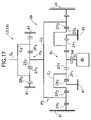
- FIG. 17 is a skeleton diagram of the electric actuator of the walking assistance system.
- a first embodiment of the present invention is explained below with reference to FIG. 1 to FIG. 7 .
- a walking assistance system of the present invention includes a backpack 11 carried by a user on the back, a pair of left and right first electric actuators 12 applying a torque to left and right hip joints, a pair of left and right second electric actuators 13 applying a torque to left and right knee joints, an abdominal belt 14 made of a flexible resin and detachably fitted around the user's abdomen, upper leg supports 15 f and 15 r made of a flexible resin, split into front and rear portions, and detachably fitted around the user's left and right thighs, lower leg supports 16 f and 16 r made of a flexible resin, split into front and rear portions, and detachably fitted around the user's left and right lower legs, and two suspenders 17 extending from a front part of the abdominal belt 14 and connected to a rear part of the abdominal belt 14 via the user's shoulders.
- FIG. 3 shows the upper leg supports 15 f and 15 r and the lower leg supports 16 f and 16 r for a left leg
- a first link 18 and a reinforcing member 19 are secured by bolts so as to hold an outer face and an inner face of each of left and right sides of the abdominal belt 14 therebetween.
- a second link 20 bendably connected to the lower end of the first link 18 via the first electric actuator 12 is secured by bolts to the outside of the rear upper leg support 15 r .
- a pivoting support for the first link 18 and the second link 20 that is, the first electric actuator 12 , is positioned outside the user's hip joint.
- An outside third link 21 and an inside third link 22 are secured by bolts to the outside and the inside respectively of the rear upper leg support 15 r
- an outside fourth link 23 and an inside fourth link 24 are secured by bolts to the outside and the inside respectively of the rear lower leg support 16 r
- the lower end of the outside third link 21 and the upper end of the outside fourth link 23 are bendably connected to each other via the second electric actuator 13
- the lower end of the inside third link 22 and the upper end of the inside fourth link 24 are bendably connected to each other via a hinge 25 .
- pivoting supports of the two third links 21 and 22 and the two fourth links 23 and 24 that is, the second electric actuator 13 and the hinge 25 , are positioned on the outside and the inside of the user's knee joint.
- an electronic control unit 26 for controlling the operation of the first electric actuators 12 and the second electric actuators 13 , an indicator 27 for indicating the state of torque generated by each of the actuators 12 and 13 , a motor driver 28 for driving a motor of each of the actuators 12 and 13 , and a power source 29 (e.g., an Ni—Zn battery) for supplying electric power to the motors and the electronic control unit 26 .
- an electronic control unit 26 for controlling the operation of the first electric actuators 12 and the second electric actuators 13
- an indicator 27 for indicating the state of torque generated by each of the actuators 12 and 13
- a motor driver 28 for driving a motor of each of the actuators 12 and 13
- a power source 29 e.g., an Ni—Zn battery
- the first electric actuators 12 and the second electric actuators 13 have a common structure, and are formed from a DC motor and a reduction gear, a casing thereof is secured by bolts to the lower end of the first link 18 , and an output shaft thereof is joined by a bolt 30 to the upper end of the second link 20 .
- Driving the first electric actuator 12 therefore generates a torque for rotating the second link 20 relative to the first link 18 , thus enabling the user's hip joint to be extended/bent.
- the second electric actuator 13 has a casing thereof secured by bolts to the lower end of the outside third link 21 and an output shaft thereof joined to the upper end of the outside fourth link 23 by a bolt 30 .
- Driving the second electric actuator 13 therefore generates a torque for rotating the outside fourth link 23 relative to the outside third link 21 , thus enabling the user's knee joint to be extended/bent.
- the structure of the first electric actuator 12 is now explained with reference to FIG. 4 to FIG. 7 .
- the structure of the second electric actuator 13 is the same as that of the first electric actuator 12 .
- a casing 41 of the first electric actuator 12 is formed in a bottomed cylindrical shape having an axis L as the center.
- the casing 41 is formed by layering a first support ring 42 , a second support ring 43 , a support plate 44 , a motor housing 45 , and a motor cover 46 and integrally securing them with a plurality of bolts 47 .
- a motor 48 is housed within the motor housing 45 and the motor cover 46
- a reduction gear 49 is housed within the first support ring 42 and the second support ring 43 .
- An input shaft Si of the reduction gear 49 is supported on the support plate 44 and the motor housing 45 via ball bearings 50 and 51 , a rotor 52 of the motor 48 is fixed to the input shaft Si, is and a stator 53 surrounding the outer periphery of the rotor 52 is fixed to the motor housing 45 .
- a permanent magnet 52 a and a coil 53 a are provided on the rotor 52 and the stator 53 respectively, and when the coil 53 a is energized, the input shaft Si rotates together with the rotor 52 .
- the reduction gear 49 includes a first planetary gear mechanism P 1 and a second planetary gear mechanism P 2 housed inside the second support ring 43 , and a third planetary gear mechanism P 3 housed inside the first support ring 42 .
- the first planetary gear mechanism P 1 is disposed radially inside the second planetary gear mechanism P 2
- the third planetary gear mechanism P 3 is disposed outside, in the axis L direction, the first and second planetary gear mechanisms P 1 and P 2 .
- the first planetary gear mechanism P 1 includes a first sun gear ZS 1 , a first ring gear ZR 1 , a plurality of first planetary gears ZP 1 , and a first carrier C 1 .
- the first sun gear ZS 1 is connected to a shaft end of the input shaft Si via an electromagnetic clutch 54 .
- the first ring gear ZR 1 is formed integrally with the inner periphery of a ring member 55 disposed rotatably around the axis L.
- the first carrier C 1 which rotatably supports the first planetary gears ZP 1 meshing simultaneously with the first sun gear ZS 1 and the first ring gear ZR 1 , is formed as part of the support plate 44 .
- the first planetary gear mechanism P 1 is therefore of a star type in which the first carrier C 1 is fixed and the first ring gear ZR 1 is rotatable, and when the first sun gear ZS 1 , which is connected to the input shaft Si via the electromagnetic clutch 54 , rotates, the rotation is reduced in speed and reversed, and output to the first ring gear ZR 1 (i.e., the ring member 55 ).
- the reduction ratio of the star type first planetary gear mechanism P 1 is defined as nr 1 /ns 1 , where ns, is an input rotational speed of the first sun gear ZS 1 and nr 1 is an output rotational speed of the first ring gear ZR 1 .
- nr 1 /ns 1 is an input rotational speed of the first sun gear ZS 1
- nr 1 is an output rotational speed of the first ring gear ZR 1 .
- the second planetary gear mechanism P 2 includes a second sun gear ZS 2 , a second ring gear ZR 2 , a plurality of second planetary gears ZP 2 , and a second carrier C 2 .
- the second sun gear ZS 2 is formed on the outer periphery of the ring member 55 , on the inner periphery of which is formed the first ring gear ZR 1 .
- the second ring gear ZR 2 is formed integrally with the inner periphery of the second support ring 43 , which is fixed to the casing 41 .
- the second carrier C 2 which rotatably supports the second planetary gears ZP 2 meshing simultaneously with the second sun gear ZS 2 and the second ring gear ZR 2 , is rotatably supported on the inner periphery of the second support ring 43 via a ball bearing 56 .
- the second planetary gear mechanism P 2 is therefore of a planetary type in which the second ring gear ZR 2 is fixed and the second carrier C 2 is rotatable, and when the second sun gear ZS 2 , which is an input member, rotates, the rotation is reduced in speed and output in the same rotational sense to the second carrier C 2 .
- the reduction ratio of the planetary type second planetary gear mechanism P 2 is defined as nc 2 /ns 2 , where ns 2 is an input rotational speed of the second sun gear ZS and nc 2 is an output rotational speed of the second carrier C 2 .
- nc 2 /ns 2 zs 2 /( zs 2 +zr 2 ).
- the third planetary gear mechanism P 3 includes a third sun gear ZS 3 , a third ring gear ZR 3 , a plurality of third planetary gears ZP 3 , and a third carrier C 3 .
- the third sun gear ZS 3 is formed integrally with the outer periphery of a central part of the second carrier C 2 of the second planetary gear mechanism P 2 .
- the third ring gear ZR 3 is formed integrally with the inner periphery of the first support ring 42 , which is fixed to the casing 41 .
- the third carrier C 3 which rotatably supports the third planetary gears ZP 3 meshing simultaneously with the third sun gear ZS 3 and the third ring gear ZR 3 , is rotatably supported on the inner periphery of the first support ring 42 via a ball bearing 57 .
- the third planetary gear mechanism P 3 is therefore of a planetary type in which the third ring gear ZR 3 is fixed and the third carrier C 3 is rotatable, and when the third sun gear ZS 3 , which is an input member, rotates, the rotation is reduced in speed and output in the same rotational sense to the output shaft So, which is integral with the third carrier C 3 .
- nc 3 /ns 1 ( ⁇ zs 1 /zr 1 ) ⁇ zs 2 /( zs 2 +zr 2 ) ⁇ zs 3 /( zs 3 +zr 3 ) ⁇ (5) and in the embodiment, since the number of teeth of each gear is set as follows:
- the reduction ratio nc 3 /ns 1 of the reduction gear 49 obtained by substituting these numbers of teeth in Equation (5) is 1/50. That is, when the input shaft Si of the reduction gear 49 rotates 50 times, the output shaft So rotates once in the opposite direction.
- the reduction gear 49 is formed by connecting the first to the third planetary gear mechanisms P 1 to P 3 , it is possible to increase the torque of the motor 48 while ensuring that there is a sufficient reduction ratio. Furthermore, since the second planetary gear mechanism P 2 is disposed so as to overlap the radially outer side of the first planetary gear mechanism P 1 , it is possible to reduce the thickness in the axis L direction of the reduction gear 49 compared with a case in which the first to the third planetary gear mechanisms P 1 to P 3 are all disposed so as to be stacked in the axis L direction.
- the first electric actuators 12 and the second electric actuators 13 can be made compact by suppressing the thickness of the reduction gear 49 to a thickness corresponding to two planetary gear mechanisms while ensuring that there is a reduction ratio corresponding to three planetary gear mechanisms, thereby enabling fitting under a user's clothing with a good appearance.
- the structure of a first electric actuator 12 related to a second embodiment of the present invention is now explained with reference to FIG. 8 to FIG. 10 .
- the structure of a second electric actuator 13 is the same as that of the first electric actuator 12 .
- a casing 41 of the first electric actuator 12 is formed in a bottomed cylindrical shape having an axis L as the center.
- the casing 41 is formed by layering a support ring 42 , a support plate 44 , a motor housing 45 , and a motor cover 46 and integrally securing them with a plurality of bolts 47 .
- a motor 48 is housed within the motor housing 45 and the motor cover 46
- a reduction lo gear 49 is housed within the support ring 42 .
- An input shaft Si of the reduction gear 49 is supported on the support plate 44 and the motor cover 46 via ball bearings 50 and 51 , a rotor 52 of the motor 48 is fixed to the input shaft Si, and a stator 53 surrounding the outer periphery of the rotor 52 is fixed to the motor housing 45 .
- a permanent magnet 52 a and a coil 53 a are provided on the rotor 52 and the stator 53 respectively, and when the coil 53 a is energized, the input shaft Si rotates together with the rotor 52 .
- the reduction gear 49 which is housed within the support ring 42 , includes a first planetary gear mechanism P 1 , a second planetary gear mechanism P 2 , and a third planetary gear mechanism P 3 ; the second planetary gear mechanism P 2 is disposed radially outside the first planetary gear mechanism P 1 , and the third planetary gear mechanism P 3 is disposed radially outside the second planetary gear mechanism P 2 .
- the first planetary gear mechanism P 1 includes a first sun gear ZS 1 , a first ring gear ZR 1 , a plurality of first planetary gears ZP 1 , and a first carrier C 1 .
- the first sun gear ZS 1 is connected to a shaft end of the input shaft Si via an electromagnetic clutch 54 .
- the first ring gear ZR 1 is formed integrally with the inner periphery of an inside ring member 55 i disposed so as to surround the axis L.
- the first carrier C 1 which rotatably supports the first planetary gears ZP 1 meshing simultaneously with the first sun gear ZS 1 and the first ring gear ZR 1 , is provided as a portion close to the center of the support plate 44 .
- the first planetary gear mechanism P 1 is therefore of a star type in which the first ring gear ZR 1 is rotatable and the first carrier C 1 is fixed, and when the first sun gear ZS 1 , which is connected to the input shaft Si via the electromagnetic clutch 54 , rotates, the rotation is reduced in speed and reversed, and output to the first ring gear ZR 1 .
- the reduction ratio of the star type first-planetary gear mechanism P 1 is defined as nr 1 /ns 1 , where ns 1 is an input rotational speed of the first sun gear ZS 1 and nr 1 is an output rotational speed of the first ring gear ZR 1 .
- zs 1 , zr 1 , and zp 1 denote the number of teeth of the first sun gear ZS 1 , the first ring gear ZR 1 , and the first planetary gear ZP 1 respectively
- the minus sign of the right side of Equation (6) indicates that the direction of rotation of the first ring gear ZR 1 is opposite to the direction of rotation of the first sun gear ZS 1 .
- the second planetary gear mechanism P 2 includes a second sun gear ZS 2 , a second ring gear ZR 2 , a plurality of second planetary gears ZP 2 , and a second carrier C 2 .
- the second sun gear ZS 2 is formed on the outer periphery of the inside ring member 55 i .
- the second ring gear ZR 2 is formed integrally with the inner periphery of an outside ring member 55 o disposed so as to surround the axis L.
- the second carrier C 2 which rotatably supports the second planetary gears ZP 2 meshing simultaneously with the second sun gear ZS 2 and the second ring gear ZR 2 , is provided as a portion close to the outer periphery of the support plate 44 .
- the second planetary gear mechanism P 2 is therefore of a star type in which the second ring gear ZR 2 is rotatable and the second carrier C 2 is fixed, and when the second sun gear ZS 2 , which is integral with the first ring gear ZR 1 , rotates, the rotation is reduced in speed and reversed, and output to the second ring gear ZR 2 .
- the reduction ratio of the star type second planetary gear mechanism P 2 is defined as nr 2 /ns 2 , where ns 2 is an input rotational speed of the second sun gear ZS 2 and nr 2 is an output rotational speed of the second ring gear ZR 2 .
- zs 2 , zr 2 , and zp 2 denote the number of teeth of the second sun gear ZS 2 , the second ring gear ZR 2 , and the second planetary gear ZP 2 , respectively
- the minus sign of the right-hand side of Equation (7) indicates that the direction of rotation of the second ring gear ZR 2 is opposite to the direction of rotation of the second sun gear ZS 2 .
- the third planetary gear mechanism P 3 includes a third sun gear ZS 3 , a third ring gear ZR 3 , a plurality of third planetary gears ZP 3 , and a third carrier C 3 .
- the third sun gear ZS 3 is formed integrally with the outer periphery of the outside ring member 55 o .
- the third ring gear ZR 3 is formed integrally with the inner periphery of the support ring 42 , which is fixed to the casing 41 .
- the third carrier C 3 which rotatably supports the third planetary gears ZP 3 meshing simultaneously with the third sun gear ZS 3 and the third ring gear ZR 3 , is rotatably supported on the inner periphery of the support ring 42 via a ball bearing 57 .
- the third planetary gear mechanism P 3 is therefore of a planetary type in which the third ring gear ZR 3 is fixed and the third carrier C 3 is rotatable, and when the third sun gear ZS 3 , which is an input member, rotates, the rotation is reduced in speed in the same direction and output to the output shaft So, which is integral with the third carrier C 3 .
- nc 3 /ns 1 ( ⁇ zs 1 /zr 1 ) ⁇ ( ⁇ zs 2 /zr 2 ) ⁇ zs 3 /(zs 3 +zr 3 ) ⁇ (10) and in the embodiment, since the number of teeth of each gear is set as follows:
- the reduction gear 49 is formed by connecting the first to the third planetary gear mechanisms P 1 to P 3 , it is possible to increase the torque of the motor 48 while ensuring that there is a sufficient reduction ratio. Furthermore, since the second planetary gear mechanism P 2 is disposed so as to overlap the radially outer side of the first planetary gear mechanism P 1 , and the third planetary gear mechanism P 3 is disposed so as to overlap the radially outer side of the second planetary gear mechanism P 2 , it is possible to reduce the thickness in the axis L direction of the reduction gear 49 compared with a case in which the first to the third planetary gear mechanisms P 1 to P 3 are all disposed so as to be stacked in the axis L direction.
- the first electric actuators 12 and the second electric actuators 13 can be made compact by suppressing the thickness of the reduction gear 49 to a thickness corresponding to one planetary gear mechanism while ensuring that there is a reduction ratio corresponding to three planetary gear mechanisms, thereby enabling fitting under a user's clothing with a good appearance.
- the structure of a first electric actuator 12 related to a third embodiment of the present invention is now explained with reference to FIG. 11 to FIG. 13 .
- the structure of a second electric actuator 13 is the same as that of the first -electric actuator 12 .
- a casing 41 of the first electric actuator 12 is formed in a bottomed cylindrical shape having an axis L as the center.
- the casing 41 is formed by layering a support ring 42 , a support plate 44 , a motor housing 45 , and a motor cover 46 and integrally securing them with a plurality of bolts 47 .
- a motor 48 is housed within the motor housing 45 and the motor cover 46
- a reduction gear 49 is housed within the support ring 42 and the support plate 44 .
- An input shaft Si of the reduction gear 49 is supported on the support plate 44 and the motor cover 46 via ball bearings 50 and 51 , a rotor 52 of the motor 48 is fixed to the input shaft Si, and a stator 53 surrounding the outer periphery of the rotor 52 is fixed to the motor housing 45 .
- a permanent magnet 52 a and a coil 53 a are provided on the rotor 52 and the stator 53 respectively, and when the coil 53 a is energized, the input shaft Si rotates together with the rotor 52 .
- the reduction gear 49 which is housed within the support ring 42 , includes a first planetary gear mechanism P 1 , a second planetary gear mechanism P 2 , and a third planetary gear mechanism P 3 ; the second planetary gear mechanism P 2 is disposed radially outside the first planetary gear mechanism P 1 , and the third planetary gear mechanism P 3 is disposed radially outside the second planetary gear mechanism P 2 .
- the first planetary gear mechanism P 1 includes a first sun gear ZS 1 , a first ring gear ZR 1 , a plurality of first planetary gears ZP 1 , and a first carrier C 1 .
- the first sun gear ZS 1 is connected to a shaft end of the input shaft Si via an electromagnetic clutch 54 .
- the first ring gear ZR 1 is formed integrally at a position close to the center of the support plate 44 so as to surround the axis L.
- the first carrier C 1 which rotatably supports the first planetary gears ZP 1 meshing simultaneously with the first sun gear ZS 1 and the first ring gear ZR 1 , is disposed rotatably around the axis L.
- the first planetary gear mechanism P 1 is therefore of a planetary type in which the first ring gear ZR 1 is fixed and the first carrier C 1 is rotatable, and when the first sun gear ZS 1 , which is connected to the input shaft Si via the electromagnetic clutch 54 , rotates, the rotation is reduced in speed in the same direction, and output to the first carrier C 1 .
- the reduction ratio of the planetary type first planetary gear mechanism P 1 is defined as nc 1 /ns 1 , where ns 1 is an input rotational speed of the first sun gear ZS 1 and nc 1 is an output rotational speed of the first carrier C 1 .
- nc 1 /ns 1 zs 1 /( zs 1 +zr 1 ).
- the second planetary gear mechanism P 2 includes a second sun gear ZS 2 , a second ring gear ZR 2 , a plurality of second planetary gears ZP 2 , and a second carrier C 2 .
- the second sun gear ZS 2 is formed on the outer periphery of the first carrier C 1 of the first planetary gear mechanism P 1 .
- the second ring gear ZR 2 is formed at a position close to the outer periphery of the support plate 44 so as to surround the axis L.
- the second carrier C 2 which rotatably supports the second planetary gears ZP 2 meshing simultaneously with the second sun gear ZS 2 and the second ring gear ZR 2 , is disposed rotatably around the axis L.
- the second planetary gear mechanism P 2 is therefore of a planetary type in which the second ring gear ZR 2 is fixed and the second carrier C 2 is rotatable, and when the second sun gear ZS 2 rotates, the rotation is reduced in speed in the same direction, and output to the second carrier C 2 .
- the reduction ratio of the planetary type second planetary gear mechanism P 2 is defined as nc 2 /ns 2 , where ns 2 is an input rotational speed of the second sun gear ZS and nc 2 is an output rotational speed of the second carrier C 2 .
- the third planetary gear mechanism P 3 includes a third sun gear ZS 3 , a third ring gear ZR 3 , a plurality of third planetary gears ZP 3 , and a third carrier C 3 .
- the third sun gear ZS 3 is formed on the outer periphery of the second carrier C 2 of the second planetary gear mechanism P 2 .
- the third ring gear ZR 3 is formed integrally with the inner periphery of the support ring 42 .
- the third carrier C 3 which rotatably supports the third planetary gears ZP 3 meshing simultaneously with the third sun gear ZS 3 and the third ring gear ZR 3 , is rotatably supported on the inner periphery of the support ring 42 via a ball bearing 57 .
- the third planetary gear mechanism P 3 is therefore of a planetary type in which the third ring gear ZR 3 is fixed and the third carrier C 3 is rotatable, and when the third sun gear ZS 3 rotates, the rotation is reduced in speed in the same direction and output to the output shaft So, which is integral with the third carrier C 3 .
- the output rotational speed nc 1 of the first carrier C 1 which is the output member of the first planetary gear mechanism P 1
- the input rotational speed ns 2 of the second sun gear ZS 2 which is the input member of the second planetary gear mechanism P 2
- the output rotational speed nc 2 of the second carrier C 2 which is the output member of the second planetary gear mechanism P 2
- the reduction ratio nc 3 /ns 3 of the third planetary gear mechanism P 3 shown in Equation (13) is given by the ratio nc 3 /ns 1 of the rotational speed nc 3 of the
- nc 3 /ns 1 ⁇ zs 1 /( zs 1 +zr 1 ) ⁇ zs 2 /( zs 2 +zr 2 ) ⁇ zs 3 /( zs 3 +zr 3 ) ⁇
- the number of teeth of each gear is set as follows:
- the reduction gear 49 is formed by connecting the first to the third planetary gear mechanisms P 1 to P 3 , it is possible to increase the torque of the motor 48 while ensuring that there is a sufficient reduction ratio. Furthermore, since the second planetary gear mechanism P 2 is disposed so as to overlap the radially outer side of the first planetary gear mechanism P 1 , and the third planetary gear mechanism P 3 is disposed so as to overlap the radially outer side of the second planetary gear mechanism P 2 , it is possible to reduce the thickness in the axis L direction of the reduction gear 49 compared with a case in which the first to the third lo planetary gear mechanisms P 1 to P 3 are all disposed so as to be stacked in the axis L direction.
- the first electric actuators 12 and the second electric actuators 13 can be made compact by suppressing the thickness of the reduction gear 49 to a thickness corresponding to one planetary gear mechanism while ensuring that there is a reduction ratio corresponding to three planetary gear mechanisms, thereby enabling fitting under a user's clothing with a good appearance.
- the structure of a first electric actuator 12 related to a fourth embodiment of the present invention is now explained with reference to FIG. 14 to FIG. 17 .
- the structure of a second electric actuator 13 is the same as that of the first electric actuator 12 .
- a casing 41 of the first electric actuator 12 is formed in a bottomed cylindrical shape having an axis L as the center.
- the casing 41 is formed by layering a first support ring 42 , a second support ring 43 , a support plate 44 , a motor housing 45 , and a motor cover 46 and integrally securing them with a plurality of bolts 47 .
- a motor 48 is housed within the motor housing 45 and the motor cover 46
- a reduction gear 49 is housed within the first support ring 42 and the second support ring 43 .
- An input shaft Si of the reduction gear 49 is supported on the support plate 44 and the motor housing 45 via ball bearings 50 and 51 , a rotor 52 of the motor 48 is fixed to the input shaft Si, and a stator 53 surrounding the outer periphery of the rotor 52 is fixed to the motor housing 45 .
- a permanent magnet 52 a and a coil 53 a are provided on the rotor 52 and the stator 53 respectively, and when the coil 53 a is energized, the input shaft Si rotates together with the rotor 52 .
- the reduction gear 49 includes a first planetary gear mechanism P 1 and a second planetary gear mechanism P 2 housed inside the second support ring 43 , and a third planetary gear mechanism P 3 housed inside the first support ring 42 .
- the first planetary gear mechanism P 1 is disposed radially inside the second planetary gear mechanism P 2
- the third planetary gear mechanism P 3 is disposed outside, in the axis L direction, the first and second planetary gear mechanisms P 1 and P 2 .
- the first planetary gear mechanism P 1 includes a first sun gear ZS 1 , a first ring gear ZR 1 , a plurality of first planetary gears ZP 1 , and a first carrier C 1 .
- the first sun gear ZS 1 is connected to a shaft end of the input shaft Si via an electromagnetic clutch 54 .
- the first ring gear ZR 1 is formed integrally with the support plate 44 so as to surround the axis L.
- the first carrier C 1 which rotatably supports the first planetary gears ZP 1 meshing simultaneously with the first sun gear ZS 1 and the first ring gear ZR 1 , is disposed rotatably around the axis L.
- the first planetary gear mechanism P 1 is therefore of a planetary type in which the first ring gear ZR 1 is fixed and the first carrier C 1 is rotatable, and when the first sun gear ZS 1 , which is connected to the input shaft Si via the electromagnetic clutch 54 , rotates, the rotation is reduced in speed in the same direction, and output to the first carrier C 1 .
- the reduction ratio of the planetary type first planetary gear mechanism P 1 is defined as nc 1 /ns 1 , where ns 1 is an input rotational speed of the first sun gear ZS 1 and nc 1 is an output rotational speed of the first carrier C 1 .
- zs 1 , zr 1 , and zp 1 denote the numbers of teeth of the first sun gear ZS 1 , the first ring gear ZR 1 , and the first planetary gear ZP 1 respectively
- the second planetary gear mechanism P 2 includes a second sun gear ZS 2 , a second ring gear ZR 2 , a plurality of second planetary gears ZP 2 , and a second carrier C 2 .
- the second sun gear ZS 2 is formed on the outer periphery of the first carrier C 1 of the first planetary gear mechanism P 1 .
- the second ring gear ZR 2 is formed integrally with the inner periphery of the second support ring 43 , which is fixed to the casing 41 .
- the second carrier C 2 which rotatably supports the second planetary gears ZP 2 meshing simultaneously with the second sun gear ZS 2 and the second ring gear ZR 2 , is rotatably supported on the inner periphery of the second support ring 43 via a ball bearing 56 .
- the second planetary gear mechanism P 2 is therefore of a planetary type in which the second ring gear ZR 2 is fixed and the second carrier C 2 is rotatable, and when the second sun gear ZS 2 , which is an input member, rotates, the rotation is reduced in speed in the same direction, and output to the second carrier C 2 .
- the reduction ratio of the planetary type second planetary gear mechanism P 2 is defined as nc 2 /ns 2 , where ns 2 is an input rotational speed of the second sun gear ZS 2 and nc 2 is an output rotational speed of the second carrier C 2 .
- the third planetary gear mechanism P 3 includes a third sun gear ZS 3 , a third ring gear ZR 3 , a plurality of third planetary gears ZP 3 , and a third carrier C 3 .
- the third sun gear ZS 3 is formed integrally with the outer periphery of a central part of the second carrier C 2 of the second planetary gear mechanism P 2 .
- the third ring gear ZR 3 is formed integrally with the inner periphery of the first support ring 42 , which is fixed to the casing 41 .
- the third carrier C 3 which rotatably supports the third planetary gears ZP 3 meshing simultaneously with the third sun gear ZS 3 and the third ring gear ZR 3 , is rotatably supported on the inner periphery of the first support ring 42 via a ball bearing 57 .
- the third planetary gear mechanism P 3 is therefore of a planetary type in which the third ring gear ZR 3 is fixed and the third carrier C 3 is rotatable, and when the third sun gear ZS 3 , which is an input member, rotates, the rotation is reduced in speed in the same direction and output to the output shaft So, which is integral with the third carrier C 3 .
- the output rotational speed nc 1 of the first carrier C 1 which is the output member of the first planetary gear mechanism P 1
- the input rotational speed ns 2 of the second sun gear ZS 2 which is the input member of the second planetary gear mechanism P 2
- the output rotational speed nc 2 of the second carrier C 2 which is the output member of the second planetary gear mechanism P 2
- the reduction ratio nc 3 /ns 3 of the third planetary gear mechanism P 3 shown in Equation (18) is given by the ratio nc 3 /ns 1 of the rotational speed nc 3 of the third
- nc 3 /ns 1 ⁇ zs 1 /( zs 1 +zr 1 ) ⁇ zs 2 /( zs 2 +zr 2 ) ⁇ zs 3 /( zs 3 +zr 3 ) ⁇ (20) and in the embodiment, since the number of teeth of each gear is set as follows:
- the reduction ratio nc 3 /ns 1 of the reduction gear 49 obtained by substituting these numbers of teeth in Equation (20) is 1/62.5. That is, when the input shaft Si of the reduction gear 49 rotates 62.5 times, the output shaft So rotates once in the same direction.
- the reduction gear 49 is formed by connecting the first to the third planetary gear mechanisms P 1 to P 3 , it is possible to increase the torque of the motor 48 while ensuring that there is a sufficient reduction ratio. Furthermore, since the second planetary gear mechanism P 2 is disposed so as to overlap the radially outer side of the first planetary gear mechanism P 1 , it is possible to reduce the thickness in the axis L direction of the reduction gear 49 compared with a case in which the first to the third planetary gear mechanisms P 1 to P 3 are all disposed so as to be stacked in the axis L direction.
- the first electric actuators 12 and the second electric actuators 13 can be made compact by suppressing the thickness of the reduction gear 49 to a thickness corresponding to two planetary gear mechanisms while ensuring that there is a reduction ratio corresponding to three planetary gear mechanisms, thereby enabling fitting lo under a user's clothing with a good appearance.
- the reduction gear 49 of the first embodiment includes the first to the third planetary gear mechanisms P 1 to P 3 , but the third planetary gear mechanism P 3 may be omitted and only the first and second planetary gear mechanisms P 1 and P 2 may be employed.
- the electromagnetic clutch 54 is disposed between the input shaft Si and the first sun gear ZS 1 , but the electromagnetic clutch 54 may be provided at any position between the input shaft Si and the output shaft So.
- the present invention can be suitably applied to a reduction gear for a walking assistance system assisting an injured person or an elderly person with weakened leg force to move.
Landscapes
- Health & Medical Sciences (AREA)
- Epidemiology (AREA)
- Pain & Pain Management (AREA)
- Physical Education & Sports Medicine (AREA)
- Rehabilitation Therapy (AREA)
- Life Sciences & Earth Sciences (AREA)
- Animal Behavior & Ethology (AREA)
- General Health & Medical Sciences (AREA)
- Public Health (AREA)
- Veterinary Medicine (AREA)
- Engineering & Computer Science (AREA)
- General Engineering & Computer Science (AREA)
- Mechanical Engineering (AREA)
- Rehabilitation Tools (AREA)
- Manipulator (AREA)
Applications Claiming Priority (9)
| Application Number | Priority Date | Filing Date | Title |
|---|---|---|---|
| JP2002-253513 | 2002-08-30 | ||
| JP2002253511A JP2004089374A (ja) | 2002-08-30 | 2002-08-30 | 歩行補助装置の減速機 |
| JP2002-253511 | 2002-08-30 | ||
| JP2002253512A JP2004089375A (ja) | 2002-08-30 | 2002-08-30 | 歩行補助装置の減速機 |
| JP2002-253512 | 2002-08-30 | ||
| JP2002253510A JP4057864B2 (ja) | 2002-08-30 | 2002-08-30 | 歩行補助装置の減速機 |
| JP2002253513A JP2004089376A (ja) | 2002-08-30 | 2002-08-30 | 歩行補助装置の減速機 |
| JP2002-253510 | 2002-08-30 | ||
| PCT/JP2003/011103 WO2004026215A1 (ja) | 2002-08-30 | 2003-08-29 | 歩行補助装置の減速機 |
Publications (2)
| Publication Number | Publication Date |
|---|---|
| US20060142105A1 US20060142105A1 (en) | 2006-06-29 |
| US7404782B2 true US7404782B2 (en) | 2008-07-29 |
Family
ID=32034342
Family Applications (1)
| Application Number | Title | Priority Date | Filing Date |
|---|---|---|---|
| US10/526,015 Expired - Fee Related US7404782B2 (en) | 2002-08-30 | 2003-08-29 | Speed reducer for walk assist apparatus |
Country Status (4)
| Country | Link |
|---|---|
| US (1) | US7404782B2 (de) |
| EP (1) | EP1547568B1 (de) |
| AU (1) | AU2003261848A1 (de) |
| WO (1) | WO2004026215A1 (de) |
Cited By (13)
| Publication number | Priority date | Publication date | Assignee | Title |
|---|---|---|---|---|
| US20100234162A1 (en) * | 2009-01-16 | 2010-09-16 | Gm Global Technology Operations, Inc. | Torque distributing drive mechanism for motorized vehicles |
| US20110105966A1 (en) * | 2008-07-23 | 2011-05-05 | Berkeley Bionics | Exoskeleton and Method for Controlling a Swing Leg of the Exoskeleton |
| US8430784B2 (en) * | 2011-08-17 | 2013-04-30 | GM Global Technology Operations LLC | Multi-speed transmission having four planetary gear sets |
| US8769819B2 (en) | 2011-10-14 | 2014-07-08 | Gm Global Technology Operations, Llc. | Methods of fabricating combination gear for stacked planetary gearset |
| US9351855B2 (en) | 2008-06-16 | 2016-05-31 | Ekso Bionics, Inc. | Powered lower extremity orthotic and method of operation |
| KR20160085109A (ko) * | 2015-01-07 | 2016-07-15 | 삼성전자주식회사 | 구동 모듈 및 이를 포함하는 운동 보조 장치 |
| US9434032B2 (en) | 2011-04-26 | 2016-09-06 | Gm Global Technology Operations, Llc | Method of assembling a stacked planetary gear set |
| US9610208B2 (en) | 2008-05-20 | 2017-04-04 | Ekso Bionics, Inc. | Device and method for decreasing energy consumption of a person by use of a lower extremity exoskeleton |
| US20190224064A1 (en) * | 2014-08-07 | 2019-07-25 | Samsung Electronics Co., Ltd. | Driving module, motion assistance apparatus including the driving module, and method of controlling the motion assistance apparatus |
| US10398617B2 (en) | 2015-04-29 | 2019-09-03 | Steering Solutions Ip Holding Corporation | Adjustable position pivot for medical assist device |
| US10500069B2 (en) * | 2015-11-05 | 2019-12-10 | Samsung Electronics Co., Ltd. | Driving module and motion assistance apparatus including the same |
| US10588811B2 (en) | 2015-04-30 | 2020-03-17 | Steering Solutions Ip Holding Corporation | Low friction gearbox for medical assist device |
| US10794453B2 (en) * | 2018-03-27 | 2020-10-06 | The Regents Of The University Of Colorado, A Body Corporate | High torque density miniature laminar gear transmission |
Families Citing this family (25)
| Publication number | Priority date | Publication date | Assignee | Title |
|---|---|---|---|---|
| US10174810B2 (en) | 2006-06-21 | 2019-01-08 | Northeastern University | Curved bearing contact system |
| US8016893B2 (en) | 2006-06-21 | 2011-09-13 | The United States Of America As Represented By The Administrator Of The National Aeronautics And Space Administration | Gear bearing drive |
| WO2009011682A1 (en) * | 2007-07-19 | 2009-01-22 | Northeastern University | Gear bearing drive |
| WO2010019300A1 (en) * | 2008-05-20 | 2010-02-18 | University Of California At Berkeley | Device and method for decreasing oxygen consumption of a person during steady walking by use of a load-carrying exoskeleton |
| DE102011107563A1 (de) * | 2011-07-16 | 2013-01-17 | Volkswagen Aktiengesellschaft | Planetenradgetriebe für ein Kraftfahrzeug |
| DE102013101864A1 (de) * | 2013-02-26 | 2014-08-28 | Hans-Erich Maul | Mehrstufiges Getriebe |
| KR102167184B1 (ko) * | 2014-08-07 | 2020-10-16 | 삼성전자주식회사 | 구동 모듈, 구동 모듈을 포함하는 운동 보조 장치 및 운동 보조 장치의 제어 방법 |
| KR102117079B1 (ko) * | 2014-10-20 | 2020-05-29 | 삼성전자주식회사 | 구동 모듈, 구동 모듈을 포함하는 운동 보조 장치 및 운동 보조 장치의 제어 방법 |
| JP6449713B2 (ja) * | 2015-04-23 | 2019-01-09 | 本田技研工業株式会社 | 動作補助装置 |
| KR102541908B1 (ko) * | 2015-07-21 | 2023-06-09 | 삼성전자주식회사 | 프레임 모듈 및 이를 포함하는 운동 보조 장치 |
| KR101814676B1 (ko) * | 2016-07-25 | 2018-01-04 | 이동찬 | 소프트 외골격 근력 보조 장치 |
| KR102637517B1 (ko) * | 2016-09-06 | 2024-02-19 | 삼성전자주식회사 | 동력 전달 기기, 운동 보조 장치 및 그 제어 방법 |
| US10583063B2 (en) * | 2016-10-01 | 2020-03-10 | Norval N. Fagan | Manual walk-assist and accessories combo |
| JP6890407B2 (ja) * | 2016-12-07 | 2021-06-18 | 住友重機械工業株式会社 | アシスト装置 |
| ES2864374T3 (es) * | 2017-02-08 | 2021-10-13 | Parker Hannifin Corp | Dispositivo de exoesqueleto de movilidad de pierna con un mecanismo de accionamiento mejorado que emplea un acoplamiento magnético |
| KR102479563B1 (ko) * | 2017-07-24 | 2022-12-20 | 삼성전자주식회사 | 운동 보조 장치 |
| KR102642206B1 (ko) * | 2018-09-12 | 2024-03-04 | 엘지이노텍 주식회사 | 모터 |
| DE102018222004A1 (de) * | 2018-12-18 | 2020-06-18 | Zf Friedrichshafen Ag | Radnabengetriebe eines Einzelradantriebes eines Kraftfahrzeugs |
| EP3911876A1 (de) * | 2019-01-16 | 2021-11-24 | Genesis Robotics and Motion Technologies, LP | Kompakte aktuatoranordnung |
| GB201915013D0 (en) | 2019-10-17 | 2019-12-04 | Genesis Robotics And Motion Tech Lp | Actuator arrangement |
| DE102019204234A1 (de) * | 2019-03-27 | 2020-10-01 | Zf Friedrichshafen Ag | Getriebevorrichtung für ein Kraftfahrzeug |
| CN112440731A (zh) * | 2019-08-27 | 2021-03-05 | 比亚迪股份有限公司 | 轮边减速器、轮边动力总成及车辆 |
| WO2021173495A1 (en) * | 2020-02-24 | 2021-09-02 | Vanderbilt University | Prosthetic knee joint with electronically-controlled transmission |
| CN112109113B (zh) * | 2020-08-31 | 2024-06-11 | 上海微电机研究所(中国电子科技集团公司第二十一研究所) | 一体化外骨骼机器人关节组件 |
| EP4268783B1 (de) * | 2021-09-17 | 2025-07-09 | Samsung Electronics Co., Ltd. | Antriebsanordnung und bewegungsunterstützungsvorrichtung damit |
Citations (11)
| Publication number | Priority date | Publication date | Assignee | Title |
|---|---|---|---|---|
| JP176480C2 (de) | 1947-12-19 | 1948-07-08 | ||
| JPS537574A (en) | 1976-06-22 | 1978-01-24 | Dorr Oliver Inc | Method of preparing sludge and its apparatus |
| JPS6173861U (de) | 1984-10-17 | 1986-05-19 | ||
| JPH03107650A (ja) | 1989-09-19 | 1991-05-08 | Komatsu Ltd | 遊星差動装置 |
| JPH03121336A (ja) | 1989-10-03 | 1991-05-23 | Nissan Motor Co Ltd | 自動変速機のギアトレーン |
| JPH04501227A (ja) | 1988-10-21 | 1992-03-05 | ヘンズリー,デーヴィッド・エリス | 伸長減速装具ヒンジ |
| JPH07163607A (ja) | 1993-12-13 | 1995-06-27 | Tokyo R & D:Kk | 階段歩行等の電動補助装置 |
| JPH08247225A (ja) | 1995-03-14 | 1996-09-24 | Shinko Electric Co Ltd | 遊星歯車減速機の自動調芯機構 |
| JPH1137226A (ja) | 1997-07-23 | 1999-02-12 | Namiki Precision Jewel Co Ltd | 小型遊星歯車減速機及びその組立方法 |
| US5993347A (en) * | 1996-12-20 | 1999-11-30 | Hyundai Motor Company | Gear train for a 6-speed automatic transmission used in vehicles |
| JP2002030124A (ja) | 2001-06-08 | 2002-01-31 | Hitachi Chem Co Ltd | 光硬化型樹脂組成物及び塗料 |
Family Cites Families (2)
| Publication number | Priority date | Publication date | Assignee | Title |
|---|---|---|---|---|
| FR1299051A (fr) * | 1961-06-07 | 1962-07-20 | Diviseur de vitesses | |
| JP2003507668A (ja) * | 1999-08-12 | 2003-02-25 | アルファ ゲトリーベバウ ゲゼルシャフト ミット ベシュレンクテル ハフツング | 遊星歯車伝動装置 |
-
2003
- 2003-08-29 EP EP03797536A patent/EP1547568B1/de not_active Expired - Lifetime
- 2003-08-29 WO PCT/JP2003/011103 patent/WO2004026215A1/ja not_active Ceased
- 2003-08-29 AU AU2003261848A patent/AU2003261848A1/en not_active Abandoned
- 2003-08-29 US US10/526,015 patent/US7404782B2/en not_active Expired - Fee Related
Patent Citations (11)
| Publication number | Priority date | Publication date | Assignee | Title |
|---|---|---|---|---|
| JP176480C2 (de) | 1947-12-19 | 1948-07-08 | ||
| JPS537574A (en) | 1976-06-22 | 1978-01-24 | Dorr Oliver Inc | Method of preparing sludge and its apparatus |
| JPS6173861U (de) | 1984-10-17 | 1986-05-19 | ||
| JPH04501227A (ja) | 1988-10-21 | 1992-03-05 | ヘンズリー,デーヴィッド・エリス | 伸長減速装具ヒンジ |
| JPH03107650A (ja) | 1989-09-19 | 1991-05-08 | Komatsu Ltd | 遊星差動装置 |
| JPH03121336A (ja) | 1989-10-03 | 1991-05-23 | Nissan Motor Co Ltd | 自動変速機のギアトレーン |
| JPH07163607A (ja) | 1993-12-13 | 1995-06-27 | Tokyo R & D:Kk | 階段歩行等の電動補助装置 |
| JPH08247225A (ja) | 1995-03-14 | 1996-09-24 | Shinko Electric Co Ltd | 遊星歯車減速機の自動調芯機構 |
| US5993347A (en) * | 1996-12-20 | 1999-11-30 | Hyundai Motor Company | Gear train for a 6-speed automatic transmission used in vehicles |
| JPH1137226A (ja) | 1997-07-23 | 1999-02-12 | Namiki Precision Jewel Co Ltd | 小型遊星歯車減速機及びその組立方法 |
| JP2002030124A (ja) | 2001-06-08 | 2002-01-31 | Hitachi Chem Co Ltd | 光硬化型樹脂組成物及び塗料 |
Cited By (24)
| Publication number | Priority date | Publication date | Assignee | Title |
|---|---|---|---|---|
| US9610208B2 (en) | 2008-05-20 | 2017-04-04 | Ekso Bionics, Inc. | Device and method for decreasing energy consumption of a person by use of a lower extremity exoskeleton |
| US9351855B2 (en) | 2008-06-16 | 2016-05-31 | Ekso Bionics, Inc. | Powered lower extremity orthotic and method of operation |
| US20110105966A1 (en) * | 2008-07-23 | 2011-05-05 | Berkeley Bionics | Exoskeleton and Method for Controlling a Swing Leg of the Exoskeleton |
| US8801641B2 (en) | 2008-07-23 | 2014-08-12 | Ekso Bionics, Inc. | Exoskeleton and method for controlling a swing leg of the exoskeleton |
| US20100234162A1 (en) * | 2009-01-16 | 2010-09-16 | Gm Global Technology Operations, Inc. | Torque distributing drive mechanism for motorized vehicles |
| US8388480B2 (en) * | 2009-01-16 | 2013-03-05 | GM Global Technology Operations LLC | Torque distributing drive mechanism for motorized vehicles |
| US9434032B2 (en) | 2011-04-26 | 2016-09-06 | Gm Global Technology Operations, Llc | Method of assembling a stacked planetary gear set |
| US8430784B2 (en) * | 2011-08-17 | 2013-04-30 | GM Global Technology Operations LLC | Multi-speed transmission having four planetary gear sets |
| US8769819B2 (en) | 2011-10-14 | 2014-07-08 | Gm Global Technology Operations, Llc. | Methods of fabricating combination gear for stacked planetary gearset |
| US11672722B2 (en) * | 2014-08-07 | 2023-06-13 | Samsung Electronics Co., Ltd. | Driving module, motion assistance apparatus including the driving module, and method of controlling the motion assistance apparatus |
| US20190224064A1 (en) * | 2014-08-07 | 2019-07-25 | Samsung Electronics Co., Ltd. | Driving module, motion assistance apparatus including the driving module, and method of controlling the motion assistance apparatus |
| KR20220000980A (ko) * | 2015-01-07 | 2022-01-04 | 삼성전자주식회사 | 구동 모듈 및 이를 포함하는 운동 보조 장치 |
| US10952917B2 (en) * | 2015-01-07 | 2021-03-23 | Samsung Electronics Co., Ltd. | Driving module and motion assistance apparatus including the same |
| US20210169728A1 (en) * | 2015-01-07 | 2021-06-10 | Samsung Electronics Co., Ltd. | Driving module and motion assistance apparatus including the same |
| US20190262213A1 (en) * | 2015-01-07 | 2019-08-29 | Samsung Electronics Co., Ltd. | Driving module and motion assistance apparatus including the same |
| KR20220127218A (ko) * | 2015-01-07 | 2022-09-19 | 삼성전자주식회사 | 구동 모듈 및 이를 포함하는 운동 보조 장치 |
| US11534360B2 (en) * | 2015-01-07 | 2022-12-27 | Samsung Electronics Co., Ltd. | Driving module and motion assistance apparatus including the same |
| US20230094084A1 (en) * | 2015-01-07 | 2023-03-30 | Samsung Electronics Co., Ltd. | Driving module and motion assistance apparatus including the same |
| KR20160085109A (ko) * | 2015-01-07 | 2016-07-15 | 삼성전자주식회사 | 구동 모듈 및 이를 포함하는 운동 보조 장치 |
| US11931310B2 (en) * | 2015-01-07 | 2024-03-19 | Samsung Electronics Co., Ltd. | Driving module and motion assistance apparatus including the same |
| US10398617B2 (en) | 2015-04-29 | 2019-09-03 | Steering Solutions Ip Holding Corporation | Adjustable position pivot for medical assist device |
| US10588811B2 (en) | 2015-04-30 | 2020-03-17 | Steering Solutions Ip Holding Corporation | Low friction gearbox for medical assist device |
| US10500069B2 (en) * | 2015-11-05 | 2019-12-10 | Samsung Electronics Co., Ltd. | Driving module and motion assistance apparatus including the same |
| US10794453B2 (en) * | 2018-03-27 | 2020-10-06 | The Regents Of The University Of Colorado, A Body Corporate | High torque density miniature laminar gear transmission |
Also Published As
| Publication number | Publication date |
|---|---|
| AU2003261848A1 (en) | 2004-04-08 |
| WO2004026215A9 (ja) | 2004-08-12 |
| EP1547568A4 (de) | 2010-05-05 |
| US20060142105A1 (en) | 2006-06-29 |
| EP1547568B1 (de) | 2013-01-02 |
| EP1547568A1 (de) | 2005-06-29 |
| WO2004026215A1 (ja) | 2004-04-01 |
Similar Documents
| Publication | Publication Date | Title |
|---|---|---|
| US7404782B2 (en) | Speed reducer for walk assist apparatus | |
| KR102529879B1 (ko) | 구동 모듈 및 이를 포함하는 운동 보조 장치 | |
| KR102662375B1 (ko) | 운동 보조 장치 | |
| KR102167184B1 (ko) | 구동 모듈, 구동 모듈을 포함하는 운동 보조 장치 및 운동 보조 장치의 제어 방법 | |
| EP3512483B1 (de) | Bebeinte mobile exoskelettvorrichtung mit verbessertem betätigungsmechanismus | |
| US12076291B2 (en) | Remote actuation configuration for powered orthotic devices | |
| US20180133894A1 (en) | Articulated robot actuator | |
| JP2016036902A (ja) | 駆動モジュール、駆動モジュールを含む運動補助装置及び運動補助装置の制御方法 | |
| JP4057864B2 (ja) | 歩行補助装置の減速機 | |
| US20200230811A1 (en) | Actuator | |
| US20220313534A1 (en) | Two stage actuator for powered mobilitity assistance devices with electrical isolation | |
| JP2004089376A (ja) | 歩行補助装置の減速機 | |
| KR102748752B1 (ko) | 구동 어셈블리 및 이를 포함하는 운동 보조 장치 | |
| EP3512484B1 (de) | Bebeinte mobile exoskelettvorrichtung mit verbessertem betätigungsmechanismus und magnetischer/elektrischer kopplung | |
| JP2004089375A (ja) | 歩行補助装置の減速機 | |
| CN109760020B (zh) | 一种具有分力模块的外骨骼系统 | |
| JP6202351B2 (ja) | 動作補助装置用アクチュエータ及び動作補助装置 | |
| JP2004089374A (ja) | 歩行補助装置の減速機 | |
| CN113944737A (zh) | 一种扁平动力装置及助力装置 | |
| KR20220102189A (ko) | 탄성 감속 구동기 및 이를 구비하는 착용형 보조장치 |
Legal Events
| Date | Code | Title | Description |
|---|---|---|---|
| AS | Assignment |
Owner name: HONDA GIKEN KOGYO KABUSHIKI KAISHA, JAPAN Free format text: ASSIGNMENT OF ASSIGNORS INTEREST;ASSIGNORS:KUDOH, HIROSHI;KATOH, HISASHI;REEL/FRAME:017141/0282;SIGNING DATES FROM 20050928 TO 20050930 |
|
| FPAY | Fee payment |
Year of fee payment: 4 |
|
| REMI | Maintenance fee reminder mailed | ||
| LAPS | Lapse for failure to pay maintenance fees | ||
| STCH | Information on status: patent discontinuation |
Free format text: PATENT EXPIRED DUE TO NONPAYMENT OF MAINTENANCE FEES UNDER 37 CFR 1.362 |
|
| STCH | Information on status: patent discontinuation |
Free format text: PATENT EXPIRED DUE TO NONPAYMENT OF MAINTENANCE FEES UNDER 37 CFR 1.362 |
|
| FP | Lapsed due to failure to pay maintenance fee |
Effective date: 20160729 |