US7430955B2 - Hydraulic arrangement - Google Patents
Hydraulic arrangement Download PDFInfo
- Publication number
- US7430955B2 US7430955B2 US11/471,006 US47100606A US7430955B2 US 7430955 B2 US7430955 B2 US 7430955B2 US 47100606 A US47100606 A US 47100606A US 7430955 B2 US7430955 B2 US 7430955B2
- Authority
- US
- United States
- Prior art keywords
- hydraulic
- control valve
- pressure
- chamber
- supply line
- Prior art date
- Legal status (The legal status is an assumption and is not a legal conclusion. Google has not performed a legal analysis and makes no representation as to the accuracy of the status listed.)
- Expired - Fee Related, expires
Links
Images



Classifications
-
- F—MECHANICAL ENGINEERING; LIGHTING; HEATING; WEAPONS; BLASTING
- F15—FLUID-PRESSURE ACTUATORS; HYDRAULICS OR PNEUMATICS IN GENERAL
- F15B—SYSTEMS ACTING BY MEANS OF FLUIDS IN GENERAL; FLUID-PRESSURE ACTUATORS, e.g. SERVOMOTORS; DETAILS OF FLUID-PRESSURE SYSTEMS, NOT OTHERWISE PROVIDED FOR
- F15B11/00—Servomotor systems without provision for follow-up action; Circuits therefor
- F15B11/003—Systems with load-holding valves
-
- E—FIXED CONSTRUCTIONS
- E02—HYDRAULIC ENGINEERING; FOUNDATIONS; SOIL SHIFTING
- E02F—DREDGING; SOIL-SHIFTING
- E02F3/00—Dredgers; Soil-shifting machines
- E02F3/04—Dredgers; Soil-shifting machines mechanically-driven
- E02F3/28—Dredgers; Soil-shifting machines mechanically-driven with digging tools mounted on a dipper- or bucket-arm, i.e. there is either one arm or a pair of arms, e.g. dippers, buckets
- E02F3/36—Component parts
- E02F3/3604—Devices to connect tools to arms, booms or the like
- E02F3/3609—Devices to connect tools to arms, booms or the like of the quick acting type, e.g. controlled from the operator seat
- E02F3/3663—Devices to connect tools to arms, booms or the like of the quick acting type, e.g. controlled from the operator seat hydraulically-operated
-
- E—FIXED CONSTRUCTIONS
- E02—HYDRAULIC ENGINEERING; FOUNDATIONS; SOIL SHIFTING
- E02F—DREDGING; SOIL-SHIFTING
- E02F9/00—Component parts of dredgers or soil-shifting machines, not restricted to one of the kinds covered by groups E02F3/00 - E02F7/00
- E02F9/20—Drives; Control devices
- E02F9/22—Hydraulic or pneumatic drives
- E02F9/226—Safety arrangements, e.g. hydraulic driven fans, preventing cavitation, leakage, overheating
-
- F—MECHANICAL ENGINEERING; LIGHTING; HEATING; WEAPONS; BLASTING
- F15—FLUID-PRESSURE ACTUATORS; HYDRAULICS OR PNEUMATICS IN GENERAL
- F15B—SYSTEMS ACTING BY MEANS OF FLUIDS IN GENERAL; FLUID-PRESSURE ACTUATORS, e.g. SERVOMOTORS; DETAILS OF FLUID-PRESSURE SYSTEMS, NOT OTHERWISE PROVIDED FOR
- F15B2211/00—Circuits for servomotor systems
- F15B2211/30—Directional control
- F15B2211/305—Directional control characterised by the type of valves
- F15B2211/30505—Non-return valves, i.e. check valves
-
- F—MECHANICAL ENGINEERING; LIGHTING; HEATING; WEAPONS; BLASTING
- F15—FLUID-PRESSURE ACTUATORS; HYDRAULICS OR PNEUMATICS IN GENERAL
- F15B—SYSTEMS ACTING BY MEANS OF FLUIDS IN GENERAL; FLUID-PRESSURE ACTUATORS, e.g. SERVOMOTORS; DETAILS OF FLUID-PRESSURE SYSTEMS, NOT OTHERWISE PROVIDED FOR
- F15B2211/00—Circuits for servomotor systems
- F15B2211/30—Directional control
- F15B2211/31—Directional control characterised by the positions of the valve element
- F15B2211/3138—Directional control characterised by the positions of the valve element the positions being discrete
-
- F—MECHANICAL ENGINEERING; LIGHTING; HEATING; WEAPONS; BLASTING
- F15—FLUID-PRESSURE ACTUATORS; HYDRAULICS OR PNEUMATICS IN GENERAL
- F15B—SYSTEMS ACTING BY MEANS OF FLUIDS IN GENERAL; FLUID-PRESSURE ACTUATORS, e.g. SERVOMOTORS; DETAILS OF FLUID-PRESSURE SYSTEMS, NOT OTHERWISE PROVIDED FOR
- F15B2211/00—Circuits for servomotor systems
- F15B2211/30—Directional control
- F15B2211/315—Directional control characterised by the connections of the valve or valves in the circuit
- F15B2211/3157—Directional control characterised by the connections of the valve or valves in the circuit being connected to a pressure source, an output member and a return line
- F15B2211/31576—Directional control characterised by the connections of the valve or valves in the circuit being connected to a pressure source, an output member and a return line having a single pressure source and a single output member
-
- F—MECHANICAL ENGINEERING; LIGHTING; HEATING; WEAPONS; BLASTING
- F15—FLUID-PRESSURE ACTUATORS; HYDRAULICS OR PNEUMATICS IN GENERAL
- F15B—SYSTEMS ACTING BY MEANS OF FLUIDS IN GENERAL; FLUID-PRESSURE ACTUATORS, e.g. SERVOMOTORS; DETAILS OF FLUID-PRESSURE SYSTEMS, NOT OTHERWISE PROVIDED FOR
- F15B2211/00—Circuits for servomotor systems
- F15B2211/30—Directional control
- F15B2211/32—Directional control characterised by the type of actuation
- F15B2211/321—Directional control characterised by the type of actuation mechanically
- F15B2211/324—Directional control characterised by the type of actuation mechanically manually, e.g. by using a lever or pedal
-
- F—MECHANICAL ENGINEERING; LIGHTING; HEATING; WEAPONS; BLASTING
- F15—FLUID-PRESSURE ACTUATORS; HYDRAULICS OR PNEUMATICS IN GENERAL
- F15B—SYSTEMS ACTING BY MEANS OF FLUIDS IN GENERAL; FLUID-PRESSURE ACTUATORS, e.g. SERVOMOTORS; DETAILS OF FLUID-PRESSURE SYSTEMS, NOT OTHERWISE PROVIDED FOR
- F15B2211/00—Circuits for servomotor systems
- F15B2211/40—Flow control
- F15B2211/455—Control of flow in the feed line, i.e. meter-in control
-
- F—MECHANICAL ENGINEERING; LIGHTING; HEATING; WEAPONS; BLASTING
- F15—FLUID-PRESSURE ACTUATORS; HYDRAULICS OR PNEUMATICS IN GENERAL
- F15B—SYSTEMS ACTING BY MEANS OF FLUIDS IN GENERAL; FLUID-PRESSURE ACTUATORS, e.g. SERVOMOTORS; DETAILS OF FLUID-PRESSURE SYSTEMS, NOT OTHERWISE PROVIDED FOR
- F15B2211/00—Circuits for servomotor systems
- F15B2211/50—Pressure control
- F15B2211/505—Pressure control characterised by the type of pressure control means
- F15B2211/50563—Pressure control characterised by the type of pressure control means the pressure control means controlling a differential pressure
- F15B2211/50581—Pressure control characterised by the type of pressure control means the pressure control means controlling a differential pressure using counterbalance valves
-
- F—MECHANICAL ENGINEERING; LIGHTING; HEATING; WEAPONS; BLASTING
- F15—FLUID-PRESSURE ACTUATORS; HYDRAULICS OR PNEUMATICS IN GENERAL
- F15B—SYSTEMS ACTING BY MEANS OF FLUIDS IN GENERAL; FLUID-PRESSURE ACTUATORS, e.g. SERVOMOTORS; DETAILS OF FLUID-PRESSURE SYSTEMS, NOT OTHERWISE PROVIDED FOR
- F15B2211/00—Circuits for servomotor systems
- F15B2211/50—Pressure control
- F15B2211/515—Pressure control characterised by the connections of the pressure control means in the circuit
- F15B2211/5158—Pressure control characterised by the connections of the pressure control means in the circuit being connected to a pressure source and an output member
-
- F—MECHANICAL ENGINEERING; LIGHTING; HEATING; WEAPONS; BLASTING
- F15—FLUID-PRESSURE ACTUATORS; HYDRAULICS OR PNEUMATICS IN GENERAL
- F15B—SYSTEMS ACTING BY MEANS OF FLUIDS IN GENERAL; FLUID-PRESSURE ACTUATORS, e.g. SERVOMOTORS; DETAILS OF FLUID-PRESSURE SYSTEMS, NOT OTHERWISE PROVIDED FOR
- F15B2211/00—Circuits for servomotor systems
- F15B2211/50—Pressure control
- F15B2211/52—Pressure control characterised by the type of actuation
- F15B2211/528—Pressure control characterised by the type of actuation actuated by fluid pressure
-
- F—MECHANICAL ENGINEERING; LIGHTING; HEATING; WEAPONS; BLASTING
- F15—FLUID-PRESSURE ACTUATORS; HYDRAULICS OR PNEUMATICS IN GENERAL
- F15B—SYSTEMS ACTING BY MEANS OF FLUIDS IN GENERAL; FLUID-PRESSURE ACTUATORS, e.g. SERVOMOTORS; DETAILS OF FLUID-PRESSURE SYSTEMS, NOT OTHERWISE PROVIDED FOR
- F15B2211/00—Circuits for servomotor systems
- F15B2211/50—Pressure control
- F15B2211/575—Pilot pressure control
- F15B2211/5753—Pilot pressure control for closing a valve
-
- F—MECHANICAL ENGINEERING; LIGHTING; HEATING; WEAPONS; BLASTING
- F15—FLUID-PRESSURE ACTUATORS; HYDRAULICS OR PNEUMATICS IN GENERAL
- F15B—SYSTEMS ACTING BY MEANS OF FLUIDS IN GENERAL; FLUID-PRESSURE ACTUATORS, e.g. SERVOMOTORS; DETAILS OF FLUID-PRESSURE SYSTEMS, NOT OTHERWISE PROVIDED FOR
- F15B2211/00—Circuits for servomotor systems
- F15B2211/70—Output members, e.g. hydraulic motors or cylinders or control therefor
- F15B2211/705—Output members, e.g. hydraulic motors or cylinders or control therefor characterised by the type of output members or actuators
- F15B2211/7051—Linear output members
- F15B2211/7053—Double-acting output members
-
- F—MECHANICAL ENGINEERING; LIGHTING; HEATING; WEAPONS; BLASTING
- F15—FLUID-PRESSURE ACTUATORS; HYDRAULICS OR PNEUMATICS IN GENERAL
- F15B—SYSTEMS ACTING BY MEANS OF FLUIDS IN GENERAL; FLUID-PRESSURE ACTUATORS, e.g. SERVOMOTORS; DETAILS OF FLUID-PRESSURE SYSTEMS, NOT OTHERWISE PROVIDED FOR
- F15B2211/00—Circuits for servomotor systems
- F15B2211/70—Output members, e.g. hydraulic motors or cylinders or control therefor
- F15B2211/72—Output members, e.g. hydraulic motors or cylinders or control therefor having locking means
Definitions
- the invention relates to a hydraulic arrangement for a tool locking device of a loader, comprising a hydraulic cylinder with a first chamber and a second chamber, which cylinder assumes a first position for unlocking and a second position for unlocking, a first supply line connected hydraulically to the first chamber, a second supply line connected hydraulically to the second chamber and a control valve hydraulically connected to the first chamber.
- Hydraulic arrangements that are used for locking implements to wheeled loaders, such as telescopic loaders or front loaders, are known per se.
- hydraulic cylinders are employed as locking cylinders so that the implements can be mounted hydraulically to the tool carriers of the loader.
- the 6/2-way valves are disposed such that no other hydraulic functions on the tool can be actuated at the same time.
- a hydraulic arrangement of the kind mentioned above is configured such that the control valve has a first position and a second position, wherein the control valve in the first position allows hydraulic fluid to flow only in the direction of the first chamber, and in the second position, allows hydraulic fluid to flow both to the first chamber and out of the first chamber and wherein the control valve can be controlled such that it assumes the first position when the hydraulic cylinder assumes its first position so as to prevent faulty operation of the hydraulic cylinder.
- control valve can latch into the second position so that the control valve has assumed a somewhat secured position when it is in the second position.
- control valve is moved to the second position manually so that the operator has to go to the control valve in order to set the second position.
- a remote control function is also conceivable, for example by means of an electric switch or also by means of a hydraulic valve control, which moves the control valve to the second position. This would still mean that the risk of faulty operation is relatively low since the operator will be forced to actuate at least one switch to activate the remote control function.
- a control pressure arrangement is provided, which brings the control valve into the first position.
- the control valve can then be switched hydraulically from the second position to the first position. It is also conceivable, however, to replace the control pressure arrangement with an electronic circuit. In this case the control valve would be configured as an electrically actuated valve and could be electrically switched from the second position to the first position.
- the control pressure arrangement has a hydraulic connection to the second chamber.
- a constant hydraulic supply to the hydraulic cylinder results in increased pressure in the control pressure arrangement until a certain switching pressure has been reached and the control valve is moved hydraulically and automatically to the first position.
- This guarantees that the switching of the control valve is directly associated with the position of the hydraulic cylinder and that the control valve is switched automatically as a function of the position of the hydraulic cylinder.
- a sensor or switch could be used, which detects the position of the hydraulic cylinder and generates a signal when the first position has been reached.
- the control pressure arrangement is provided with a pressure control valve that opens in the direction of the control valve, the pressure present in the second chamber being applied to said pressure control valve. This way it is guaranteed that a certain control pressure has to be reached before hydraulic control pressure is applied to the control pressure line of the control valve.
- the control pressure arrangement furthermore comprises a non-return valve that opens in the direction of the first chamber, wherein the non-return valve is hydraulically connected to the second chamber parallel to the pressure control valve. This way the control pressure building in the control pressure line can be reduced when the switching process of the control valve has been actuated.
- the control pressure arrangement preferably comprises a means for disconnecting the pressure, particularly a screw plug, which allows the control pressure to be cut off to switch the control valve. This allows an operator to block the automatic control pressure arrangement for the control valve or deactivate the control pressure arrangement.
- the means for disconnecting the pressure is preferably disposed between the pressure control valve and the second supply line.
- This offers the advantage that the pressure for the pressure control valve can be set to such a value, which ensures that the pressure is not reached already as a result of the friction of the hydraulic cylinder and/or the parts connected thereto, thus accidentally moving the control valve to the first position. If the friction is too high and the control valve continues to be switched to the first position, the screw plug can offer relief because in principle it is open, but can also be closed. Consequently, the control valve can be adjusted arbitrarily and the hydraulic cylinder can be moved from the second position to the first without automatically pushing the control valve into the first position. This operating mode, however, is not desirable because it is associated with the risk that the operator may forget to switch the control valve manually into the first control position.
- the means for disconnecting the pressure is disposed between the control valve and the first supply line and a non-return valve, which opens in the direction of the first supply line, is disposed between the means for disconnecting the pressure and the first supply line.
- a non-return valve which opens in the direction of the first supply line
- the hydraulic arrangement is preferably configured as a valve block, particularly in an end plate design. It is however also conceivable to dispose the components required to achieve the hydraulic arrangement according to the invention separately.
- valve block of this type can also be provided with additional connections, to which further electrically actuated valves, for example 6/2-way valves, can be flanged.
- a hydraulic arrangement according to the invention is particularly suited as a locking system for an implement of a loader, creating greater security in terms of operator faults than with the conventional locking systems.
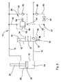
- FIG. 1 is a schematic diagram of a first embodiment of a hydraulic arrangement according to the invention
- FIG. 2 is a schematic diagram of a second embodiment of a hydraulic arrangement according to the invention.
- FIG. 3 is a schematic diagram according to the embodiment of FIG. 1 in a valve block design.
- FIG. 1 illustrates a hydraulic arrangement 10 , comprising a hydraulic cylinder 12 , a first supply line 14 , a second supply line 16 , a control valve 18 and a control pressure arrangement 20 .
- the hydraulic cylinder 12 can be connected to a mechanical system, which is not shown and serves the locking and unlocking of an implement in relation to a tool carrier.
- the supply lines 14 , 16 are connected in the familiar fashion to a hydraulic supply device 22 , which is not shown in detail and comprises a hydraulic tank, a hydraulic pump and a control device for controlling the hydraulic fluid pumped by the hydraulic pump and/or for the hydraulic actuation of the hydraulic cylinder 12 .
- the hydraulic cylinder 12 comprises a first chamber 24 and a second chamber 26 as well as a piston 30 connected to a piston rod 28 .
- the chamber of the hydraulic cylinder 12 on the piston side represents the first chamber 24 and the chamber on the rod side the second chamber 26 .
- the chambers 24 , 26 of the hydraulic cylinder can of course also be associated vice versa to the piston rod 28 and the piston 30 .
- the first chamber 24 is hydraulically connected to the first supply line 14 .
- the second chamber 26 is connected to the second supply line 16 .
- a mechanical system is actuated serving the locking and/or unlocking of an implement (not shown) connected to a tool carrier, which is not shown, for example a bucket or a fork of a loader.
- the control valve 18 is disposed in the first supply line 14 . It is preferably configured as a valve gate and has a first position 32 and a second position 34 and is pushed into the first position by an adjustment spring 36 .
- the control valve 18 furthermore comprises a control pressure connection 38 , which is associated with the first position 32 and via which the control valve 18 can be hydraulically switched into the first position 32 .
- the control valve 18 can be brought into the second position 34 by means of a manual actuating device 40 associated with the second position 34 .
- the actuating device 40 additionally comprises a latching device 42 , which allows the control valve 18 to latch into the second position 34 following the manual actuation.
- the first position 32 is configured such that the flow of hydraulic fluid through the first supply line 14 is permitted only in the direction of the first chamber 24 of the hydraulic cylinder 12 .
- the control valve 18 closes in the opposite direction without leakage.
- the second position 34 is configured such that the flow of hydraulic fluid through the first supply line 14 is permitted in both directions, i.e. both to the first chamber 24 of the hydraulic cylinder 12 and also out of the first chamber 24 of the hydraulic cylinder 12 .
- the control pressure arrangement 20 comprises first and second hydraulic lines 50 , 52 , wherein the first hydraulic line 50 represents a control pressure line from the second supply line 16 to the control pressure connection 38 of the control valve 18 .
- the second hydraulic line 52 represents a bypass line, which extends between the first hydraulic line 50 and the second supply line 16 and has a common connecting point 54 with the first hydraulic line 50 .
- a pressure control valve 56 is disposed between the connecting point 54 and the second supply line 16 , which valve is pre-stressed in a closed position by an adjustment spring 58 and can be activated via a control pressure line 60 .
- a non-return valve 62 which opens in the direction of the second supply line 16 , is disposed in the second hydraulic line 52 .
- a means 64 for disconnecting the pressure which is configured for example as a screw plug, is disposed between the pressure control valve 56 and the second supply line 16 .
- hydraulic pressure is applied to the second chamber 26 of the hydraulic cylinder 12 in order to retract the hydraulic cylinder 12 and/or the piston rod 28 and bring the hydraulic cylinder 12 into a first position, i.e., an unlocking position.
- hydraulic pressure is applied to the first chamber 24 in order to extend the hydraulic cylinder 12 and/or the piston rod 28 and bring the hydraulic cylinder 12 into a second position, i.e., a locking position.
- hydraulic fluid pressure is applied to the first supply line 14 via the hydraulic supply device 22 .
- the control valve 18 has hereby assumed a first position 32 , i.e. the flow of hydraulic fluid is only permitted in the direction of the first chamber 24 .
- the first chamber 24 is filled with hydraulic fluid and the hydraulic cylinder 12 is moved into the second position, i.e. the locking position. Since the control valve 18 in the first position 32 does not allow the flow of hydraulic fluid out of the first chamber 24 , the hydraulic cylinder 12 remains in the locking position, even if hydraulic fluid pressure were applied to the second supply line 16 and/or the second chamber 26 . Only by switching the control valve 18 to the second position 34 can the hydraulic fluid be discharged from the first chamber 24 .
- an operator first has to manually actuate the control valve 18 , which then latches into the second position 34 . Only then can hydraulic fluid pressure be applied to the second chamber by applying pressure to the second supply line, which is achieved by controlling the supply device 22 accordingly. Since in the second position 34 of the control valve 18 the flow of hydraulic fluid is permitted in both directions, the hydraulic fluid can flow out of the first chamber 24 so that the hydraulic cylinder 12 is moved into the first position, i.e. the unlocking position. As soon as the hydraulic cylinder 12 has assumed the first position, the pressure in the second chamber 26 and/or in the second supply line 16 increases, and consequently also in the first hydraulic line 50 .
- the pressure increase causes the pressure control valve 56 to be opened via the control pressure line 60 and a control pressure to be applied to the control valve 18 , which moves it back to the first position 32 .
- the built-up control pressure can be relieved via the non-return valve 62 and/or the hydraulic fluid can be discharged via the second supply line 16 when the hydraulic pressure in the second supply line 16 has dropped.
- the hydraulic cylinder 12 can now be extended again in another cycle and moved into the locking position. As already described above, it can only be retracted again, i.e. be brought into the unlocking position, when the control valve 18 has first been brought into the second position 34 by the operator.
- the screw plug 64 serves the disconnection of the opening pressure for the pressure control valve 56 .
- the pressure applied on the pressure control valve 56 can therefore be cut off, ensuring that a control pressure is not achieved already from the friction of the hydraulic cylinder 12 and/or the associated locking mechanism or components, accidentally moving the control valve 18 to the first position 32 . If the friction is too high and the control valve 18 continues to be switched to the first position, the screw plug 64 can offer relief because in principle it is open, but it can also be closed. Consequently, the control valve 18 can be adjusted arbitrarily and the hydraulic cylinder 12 can be moved from the second position to the first without automatically pushing the control valve 18 into the first position 32 .
- a third hydraulic line 66 is provided, which extends from the first hydraulic line 50 to the first supply line 14 .
- another connecting point 67 is provided between the connecting point 54 and the control valve 18 , which point connects the third hydraulic line 66 to the first hydraulic line 50 .
- the screw plug is disposed in the third hydraulic line 66 and acts as a means 64 for disconnecting the pressure.
- a non-return valve 68 which opens in the direction of the first supply line 14 , is provided between the means 64 for disconnecting the pressure and the first supply line 14 .
- the function essentially corresponds to the function described in FIG. 1 and only represents another possibility for eliminating the above-described pressure cut-off problem with high frictional resistance on the hydraulic cylinder 12 or on the locking device.
- the screw plug illustrated in FIG. 2 is closed. If the screw plug 64 is opened, the hydraulic fluid supplying the control pressure for the control valve can be discharged via the non-return valve 68 . This way the control pressure device can be quasi deactivated and/or be operated without effect so that no automatic pressure control is performed for switching the control valve 18 to the first position 32 .
- the hydraulic arrangement according to the invention is preferably configured as a valve block 70 , as is shown in the schematic illustration in FIG. 3 .
- the configuration of the hydraulic arrangement as a valve block 70 in the end plate design makes it possible to equip the valve block 70 with suitable connections for connecting hydraulic quick couplings 72 . This way the hydraulic arrangement can be produced in a particularly compact and space-saving manner.
- the valve block 70 is disposed as a connected module between the hydraulic cylinder 12 and the quick couplings 72 .
- the concept of the valve block design illustrated in FIG. 3 is suited both for the example from FIG. 1 and for the example from FIG. 2 .
- control valve 18 can also be actuated electronically, which is triggered by a position sensor positioned on the hydraulic cylinder 12 , wherein the first position or the second position of the hydraulic cylinder 12 is detected and thereupon a corresponding switch signal is generated for an electronic control connected to the control valve 18 .
Landscapes
- Engineering & Computer Science (AREA)
- General Engineering & Computer Science (AREA)
- Mechanical Engineering (AREA)
- Mining & Mineral Resources (AREA)
- Civil Engineering (AREA)
- Structural Engineering (AREA)
- Physics & Mathematics (AREA)
- Fluid Mechanics (AREA)
- Fluid-Pressure Circuits (AREA)
Applications Claiming Priority (2)
| Application Number | Priority Date | Filing Date | Title |
|---|---|---|---|
| DE102005033535A DE102005033535A1 (de) | 2005-07-14 | 2005-07-14 | Hydraulische Anordnung |
| DE102005033535.7 | 2005-07-14 |
Publications (2)
| Publication Number | Publication Date |
|---|---|
| US20070022750A1 US20070022750A1 (en) | 2007-02-01 |
| US7430955B2 true US7430955B2 (en) | 2008-10-07 |
Family
ID=36954470
Family Applications (1)
| Application Number | Title | Priority Date | Filing Date |
|---|---|---|---|
| US11/471,006 Expired - Fee Related US7430955B2 (en) | 2005-07-14 | 2006-06-20 | Hydraulic arrangement |
Country Status (3)
| Country | Link |
|---|---|
| US (1) | US7430955B2 (de) |
| EP (1) | EP1743979B1 (de) |
| DE (1) | DE102005033535A1 (de) |
Cited By (7)
| Publication number | Priority date | Publication date | Assignee | Title |
|---|---|---|---|---|
| US20110209608A1 (en) * | 2010-02-26 | 2011-09-01 | Trent Randall Stefek | Tool coupler assembly |
| US8684623B2 (en) | 2012-05-30 | 2014-04-01 | Caterpillar Inc. | Tool coupler having anti-release mechanism |
| US8869437B2 (en) | 2012-05-30 | 2014-10-28 | Caterpillar Inc. | Quick coupler |
| US8974137B2 (en) | 2011-12-22 | 2015-03-10 | Caterpillar Inc. | Quick coupler |
| US20150152624A1 (en) * | 2013-05-06 | 2015-06-04 | Hyundai Heavy Industries Co., Ltd. | Swing device of evacuator having anti-sliding device |
| US9217235B2 (en) | 2012-05-30 | 2015-12-22 | Caterpillar Inc. | Tool coupler system having multiple pressure sources |
| US9228314B2 (en) | 2013-05-08 | 2016-01-05 | Caterpillar Inc. | Quick coupler hydraulic control system |
Families Citing this family (7)
| Publication number | Priority date | Publication date | Assignee | Title |
|---|---|---|---|---|
| US7637479B2 (en) * | 2008-04-24 | 2009-12-29 | Emhiser Research Limited | Hydraulic pumping cylinder and method of pumping hydraulic fluid |
| US9617129B2 (en) * | 2010-03-16 | 2017-04-11 | Brookefield Hunter, Inc. | Hydraulic pumping cylinder and method of pumping hydraulic fluid |
| US20140158962A1 (en) * | 2011-03-16 | 2014-06-12 | Brookfield Hunter, Inc. | Hydraulic pumping cylinder and method of pumping hydraulic fluid |
| DE102012107567B4 (de) * | 2012-08-17 | 2015-03-19 | Lehnhoff Hartstahl Gmbh & Co. Kg | Schnellwechsler, Verfahren zum Betreiben eines Schnellwechslers und Schnellwechselvorrichtung |
| DE102018115249A1 (de) * | 2018-06-25 | 2020-01-02 | Lehnhoff Hartstahl Gmbh | Schnellwechsler und Schnellwechselvorrichtung mit einem Schnellwechsler |
| DE102022202288A1 (de) | 2022-03-08 | 2023-09-14 | Robert Bosch Gesellschaft mit beschränkter Haftung | Arbeitsvorrichtung mit einem Ventil, welches wenigstens eine gesonderte Entleerstellung hat |
| SE547138C2 (en) * | 2023-07-03 | 2025-04-29 | Rototilt Group Ab | Pressure monitoring system for a tiltrotator |
Citations (7)
| Publication number | Priority date | Publication date | Assignee | Title |
|---|---|---|---|---|
| US4850790A (en) * | 1988-06-27 | 1989-07-25 | J. I. Case Company | Hydraulically actuated coupler for industrial, agricultural, or earth-moving vehicle |
| US6098647A (en) * | 1996-02-28 | 2000-08-08 | Beringer-Hydraulik Ag | Load-holding brake valve |
| DE19847501C2 (de) | 1998-10-15 | 2002-06-20 | Wessel Hydraulik | Steuer- und Anzeigevorrichtung für einen doppelt wirkender Verstellzylinder |
| US6431049B1 (en) | 2000-08-24 | 2002-08-13 | Jem Technical Marketing Co., Inc. | Manifold for maintaining a latch actuator under pressure and accommodating leaks |
| DE69913590T2 (de) | 1998-03-18 | 2004-09-30 | Mailleux S.A. | Hydraulisches Verriegelungssystem für ein Laderwerkzeug |
| DE69821776T2 (de) | 1997-05-21 | 2004-10-07 | Accima Ab Lindome | Vorrichtung zur lösbaren kupplung eines werkzeugs an einen ausleger einer baggermaschine |
| US20040244575A1 (en) | 2003-01-31 | 2004-12-09 | Fatemi Ray S. | Electrical and hydraulic control system for attachment coupling system |
-
2005
- 2005-07-14 DE DE102005033535A patent/DE102005033535A1/de not_active Withdrawn
-
2006
- 2006-06-20 US US11/471,006 patent/US7430955B2/en not_active Expired - Fee Related
- 2006-07-11 EP EP06116997A patent/EP1743979B1/de not_active Not-in-force
Patent Citations (8)
| Publication number | Priority date | Publication date | Assignee | Title |
|---|---|---|---|---|
| US4850790A (en) * | 1988-06-27 | 1989-07-25 | J. I. Case Company | Hydraulically actuated coupler for industrial, agricultural, or earth-moving vehicle |
| US6098647A (en) * | 1996-02-28 | 2000-08-08 | Beringer-Hydraulik Ag | Load-holding brake valve |
| DE69821776T2 (de) | 1997-05-21 | 2004-10-07 | Accima Ab Lindome | Vorrichtung zur lösbaren kupplung eines werkzeugs an einen ausleger einer baggermaschine |
| DE69913590T2 (de) | 1998-03-18 | 2004-09-30 | Mailleux S.A. | Hydraulisches Verriegelungssystem für ein Laderwerkzeug |
| DE19847501C2 (de) | 1998-10-15 | 2002-06-20 | Wessel Hydraulik | Steuer- und Anzeigevorrichtung für einen doppelt wirkender Verstellzylinder |
| US6431049B1 (en) | 2000-08-24 | 2002-08-13 | Jem Technical Marketing Co., Inc. | Manifold for maintaining a latch actuator under pressure and accommodating leaks |
| US20040244575A1 (en) | 2003-01-31 | 2004-12-09 | Fatemi Ray S. | Electrical and hydraulic control system for attachment coupling system |
| US7047866B2 (en) * | 2003-01-31 | 2006-05-23 | Jrb Attachments, Llc | Electrical and hydraulic control system for attachment coupling system |
Cited By (8)
| Publication number | Priority date | Publication date | Assignee | Title |
|---|---|---|---|---|
| US20110209608A1 (en) * | 2010-02-26 | 2011-09-01 | Trent Randall Stefek | Tool coupler assembly |
| US8281506B2 (en) | 2010-02-26 | 2012-10-09 | Caterpillar Inc. | Tool coupler assembly |
| US8974137B2 (en) | 2011-12-22 | 2015-03-10 | Caterpillar Inc. | Quick coupler |
| US8684623B2 (en) | 2012-05-30 | 2014-04-01 | Caterpillar Inc. | Tool coupler having anti-release mechanism |
| US8869437B2 (en) | 2012-05-30 | 2014-10-28 | Caterpillar Inc. | Quick coupler |
| US9217235B2 (en) | 2012-05-30 | 2015-12-22 | Caterpillar Inc. | Tool coupler system having multiple pressure sources |
| US20150152624A1 (en) * | 2013-05-06 | 2015-06-04 | Hyundai Heavy Industries Co., Ltd. | Swing device of evacuator having anti-sliding device |
| US9228314B2 (en) | 2013-05-08 | 2016-01-05 | Caterpillar Inc. | Quick coupler hydraulic control system |
Also Published As
| Publication number | Publication date |
|---|---|
| DE102005033535A1 (de) | 2007-01-18 |
| US20070022750A1 (en) | 2007-02-01 |
| EP1743979A1 (de) | 2007-01-17 |
| EP1743979B1 (de) | 2011-08-10 |
Similar Documents
| Publication | Publication Date | Title |
|---|---|---|
| US7430955B2 (en) | Hydraulic arrangement | |
| US9382686B2 (en) | Quick coupler | |
| US9834904B2 (en) | Quick-coupler | |
| CN103415665B (zh) | 用于动力机的设备联接系统 | |
| US9689139B2 (en) | Quick coupler | |
| US7337610B2 (en) | Hydraulic arrangement | |
| US10323379B2 (en) | Quick coupler with independent locking element and securing element | |
| KR20160142848A (ko) | 작업 기계용 신속 커플러 제어 디바이스 | |
| JP2005003183A (ja) | 建設機械の油圧回路 | |
| US11753801B2 (en) | Hydraulic drive system | |
| US20110120297A1 (en) | Hydraulic Circuit | |
| CN105518312A (zh) | 流体压控制装置 | |
| GB2516341A (en) | Flow responsive latch for holding a spool valve in an open position | |
| GB2330869A (en) | Movable member : fluid-pressure mover : pressure control | |
| CN101379248B (zh) | 用于附件安装装置的控制回路 | |
| US20110088785A1 (en) | Safety feature for stuck valve | |
| CA3189117A1 (en) | I-lock coupler | |
| US3088489A (en) | Detent release for flow control valves | |
| US6418715B1 (en) | Hydraulic actuating arrangement | |
| US4011959A (en) | Bucket-positioner circuit with "no detent" operation | |
| US9574579B2 (en) | Multiple fluid pump combination circuit | |
| US3519155A (en) | Bucket positioning device | |
| NL1014661C2 (nl) | Hydraulische actuator. | |
| CN116261617B (zh) | 气动伸缩式桅杆 | |
| CN112281960A (zh) | 一种电控快换系统及装载机 |
Legal Events
| Date | Code | Title | Description |
|---|---|---|---|
| AS | Assignment |
Owner name: DEERE & COMPANY, ILLINOIS Free format text: ASSIGNMENT OF ASSIGNORS INTEREST;ASSIGNOR:BITTER, MARCUS;REEL/FRAME:017991/0471 Effective date: 20060612 |
|
| FPAY | Fee payment |
Year of fee payment: 4 |
|
| REMI | Maintenance fee reminder mailed | ||
| LAPS | Lapse for failure to pay maintenance fees | ||
| STCH | Information on status: patent discontinuation |
Free format text: PATENT EXPIRED DUE TO NONPAYMENT OF MAINTENANCE FEES UNDER 37 CFR 1.362 |
|
| STCH | Information on status: patent discontinuation |
Free format text: PATENT EXPIRED DUE TO NONPAYMENT OF MAINTENANCE FEES UNDER 37 CFR 1.362 |
|
| FP | Lapsed due to failure to pay maintenance fee |
Effective date: 20161007 |