US7464525B2 - Intake conveyor mechanism control for an agricultural working machine - Google Patents
Intake conveyor mechanism control for an agricultural working machine Download PDFInfo
- Publication number
- US7464525B2 US7464525B2 US11/430,777 US43077706A US7464525B2 US 7464525 B2 US7464525 B2 US 7464525B2 US 43077706 A US43077706 A US 43077706A US 7464525 B2 US7464525 B2 US 7464525B2
- Authority
- US
- United States
- Prior art keywords
- working machine
- agricultural working
- switching valve
- hydraulic
- valve system
- Prior art date
- Legal status (The legal status is an assumption and is not a legal conclusion. Google has not performed a legal analysis and makes no representation as to the accuracy of the status listed.)
- Expired - Fee Related, expires
Links
Images


Classifications
-
- F—MECHANICAL ENGINEERING; LIGHTING; HEATING; WEAPONS; BLASTING
- F16—ENGINEERING ELEMENTS AND UNITS; GENERAL MEASURES FOR PRODUCING AND MAINTAINING EFFECTIVE FUNCTIONING OF MACHINES OR INSTALLATIONS; THERMAL INSULATION IN GENERAL
- F16H—GEARING
- F16H61/00—Control functions within control units of change-speed- or reversing-gearings for conveying rotary motion ; Control of exclusively fluid gearing, friction gearing, gearings with endless flexible members or other particular types of gearing
- F16H61/38—Control of exclusively fluid gearing
- F16H61/40—Control of exclusively fluid gearing hydrostatic
- F16H61/4157—Control of braking, e.g. preventing pump over-speeding when motor acts as a pump
-
- A—HUMAN NECESSITIES
- A01—AGRICULTURE; FORESTRY; ANIMAL HUSBANDRY; HUNTING; TRAPPING; FISHING
- A01D—HARVESTING; MOWING
- A01D75/00—Accessories for harvesters or mowers
- A01D75/18—Safety devices for parts of the machines
- A01D75/187—Removing foreign objects
-
- F—MECHANICAL ENGINEERING; LIGHTING; HEATING; WEAPONS; BLASTING
- F16—ENGINEERING ELEMENTS AND UNITS; GENERAL MEASURES FOR PRODUCING AND MAINTAINING EFFECTIVE FUNCTIONING OF MACHINES OR INSTALLATIONS; THERMAL INSULATION IN GENERAL
- F16H—GEARING
- F16H61/00—Control functions within control units of change-speed- or reversing-gearings for conveying rotary motion ; Control of exclusively fluid gearing, friction gearing, gearings with endless flexible members or other particular types of gearing
- F16H61/38—Control of exclusively fluid gearing
- F16H61/40—Control of exclusively fluid gearing hydrostatic
- F16H61/4043—Control of a bypass valve
-
- F—MECHANICAL ENGINEERING; LIGHTING; HEATING; WEAPONS; BLASTING
- F16—ENGINEERING ELEMENTS AND UNITS; GENERAL MEASURES FOR PRODUCING AND MAINTAINING EFFECTIVE FUNCTIONING OF MACHINES OR INSTALLATIONS; THERMAL INSULATION IN GENERAL
- F16H—GEARING
- F16H61/00—Control functions within control units of change-speed- or reversing-gearings for conveying rotary motion ; Control of exclusively fluid gearing, friction gearing, gearings with endless flexible members or other particular types of gearing
- F16H61/38—Control of exclusively fluid gearing
- F16H61/40—Control of exclusively fluid gearing hydrostatic
- F16H61/4078—Fluid exchange between hydrostatic circuits and external sources or consumers
- F16H61/4104—Flushing, e.g. by using flushing valves or by connection to exhaust
-
- Y—GENERAL TAGGING OF NEW TECHNOLOGICAL DEVELOPMENTS; GENERAL TAGGING OF CROSS-SECTIONAL TECHNOLOGIES SPANNING OVER SEVERAL SECTIONS OF THE IPC; TECHNICAL SUBJECTS COVERED BY FORMER USPC CROSS-REFERENCE ART COLLECTIONS [XRACs] AND DIGESTS
- Y10—TECHNICAL SUBJECTS COVERED BY FORMER USPC
- Y10S—TECHNICAL SUBJECTS COVERED BY FORMER USPC CROSS-REFERENCE ART COLLECTIONS [XRACs] AND DIGESTS
- Y10S56/00—Harvesters
- Y10S56/11—Hydraulic
Definitions
- the present invention relates to an agricultural working machine with intake conveyor mechanisms which are hydraulically driven via a hydraulic circuit.
- a system of this type was made known in DE 100 36 612 A1, for example.
- the hydraulically-driven intake conveyor mechanisms which are designed as intake rollers provided in pairs—convey a flow of crop material between them, the crop-material flow being transferred in the rear region to a crop-material chopping device, such as a chopper drum. Since the crop-material flow often contains foreign objects, such as metallic pieces or stones, which can cause serious damage to the chopper drum as it rotates at a high rate of speed, a “quick stop” function is assigned to the intake conveyor mechanisms.
- a shut-off signal for the intake conveyor mechanisms is generated in a control unit.
- a valve combination be assigned to the hydraulic drive of the intake conveyor mechanisms, the valve combination being composed of a main control valve and a pilot directional control valve, the foreign object detection device immediately triggering—when foreign objects are detected—a switching procedure at the pilot directional control valve that induces the quick stop.
- the object of the present invention is to avoid the disadvantages of the related art described above, and to provide, in particular, a quick stop of the intake conveyor mechanisms when foreign objects are drawn in, with a minimum amount of components and installation space.
- an agricultural working machine comprising intake conveyor mechanisms; a hydraulic circuit via which said intake conveyor mechanisms are hydraulically driven and including at least one hydraulic motor which drives said intake conveyor mechanisms; at least one switching valve system for interrupting or releasing a flow of hydraulic oil being assigned to said at least one hydraulic motor, said switching valve system being configured for interrupting or releasing the flow of hydraulic oil to said hydraulic motor as a function of a signal from a foreign-object position detection device, said switching valve system including at least one braking function for said at least one hydraulic motor, and a section of said hydraulic circuit which realizes said at least one braking function is essentially free of elasticities.
- the switching valve system according to the present invention includes at least one braking function for the at least one hydromotor, and the section of the hydraulic circuit which realizes the braking function is essentially free of elasticities, it is ensured that, when foreign objects are detected in the crop-material flow, it is possible to abruptly stop the intake and pre-compression rollers, since it is not necessary to overcome elasticity-related inertias.
- a compact embodiment of the hydraulic circuit, according to the present invention, that has few components is attained when the switching valve system is capable of being operated in a “normal operation” operating state, and at least one “quick stop” operating state.
- the switching valve system makes it possible, when in the “normal operation” operating state, for pressure to be applied to the motor and for the hydraulic medium to be purged.
- a particularly advantageous embodiment of the present invention is attained when the switching valve system, when in the “quick stop” operating state, runs through a working cycle in which, in an initial step, the delivery of hydraulic medium to the hydromotor is at least partially interrupted, the purging of hydraulic medium is halted in a further step, and, in at least one third step, the hydromotor is braked. In this manner, the entire “quick stop” operating state is carried out using a single valve system.
- the “quick stop” operating state is realized in a compact, effective manner having a simple design when the switching valve system is designed as a proportionally servo valve, the movement of the valve piston of which can be controlled via the control of at least two control cylinders.
- control cylinders can be controlled independently of each other.
- the valve piston that realizes the steps of the working cycle in the “quick stop” operating state includes a piston surface that is contacted on diametrically opposed sides by the cylinder surfaces of the at least two control cylinders. In this manner, the valve piston can be guided by the control cylinders in a reliable manner, using a simple design.
- One control cylinder is designed as a closing cylinder and is acted upon continually with a control pressure
- the further control cylinder is designed as an opening cylinder
- the control pressure that can be applied to the further control cylinder can be switched on or off.
- the switching valve system is switched from the “normal operation” operating state to the “quick stop” operating state by switching off the control pressure of the further control cylinder.
- a brake valve is assigned—in an advantageous embodiment of the present invention—to the hydraulic circuit in such a manner that the rotational motion of the hydropump and the working units operatively connected with it are braked.
- an evaluation and control unit is assigned to the foreign-object detection device in a manner known per se, the evaluation and control unit generating, as a function of a position-detection signal X from foreign-object detection device, a quick-stop signal Y to switch the switching valve system to the “quick stop” operating state.
- the at least two control cylinders in the switching valve system are in a state of equilibrium in the “normal operation” operating state, and they are in a state of equilibrium for at least part of the time during execution of the third step in the working cycle of the switching valve system in the “quick stop” operating state.
- the state of equilibrium between the control cylinders in the “normal operation” operating state can be achieved by using matched cylinder-surface designs of the control cylinders and/or by applying controlled pressures of the hydraulic medium to the control cylinders.
- the state of equilibrium in the “quick stop” operating state is reliably maintained when, essentially at the end of the third step in the working cycle, the resultant pressure force of the pressurized control cylinder is in equilibrium with the reaction force, which is a function of the differential surface of the valve piston and a banking-up pressure which acts on the valve piston.
- the first step in the working cycle of the proportionally servo valve according to the present invention is realized by assigning a by-pass piston to the closing cylinder, at least one by-pass bore of the by-pass piston opening a by-pass line while the valve piston moves—in the first step of the working cycle—via which at least a portion of the hydraulic medium flowing to the hydromotor is conducted away.
- the valve piston has a restrictor which, in the second step of the working cycle, interrupts the connection between the working connection and an exchange portion of oil-channel.
- the valve piston has restrictor slits on one end which, in the third step of the working cycle, close the return line from the hydromotor to the hydropump while the valve body is moving, the hydraulic medium being supplied subsequently by the hydropump, which creates a banking-up pressure for braking the hydromotors, the banking-up pressure preferably being within the range of the permissible operating pressure.
- a large number of restrictor points is assigned to the valve piston such that the passage cross-section exposed to the hydraulic medium changes continually as a function of the path traveled by the valve piston.
- control edges and/or restrictor points are assigned to the at least two control cylinders such that the motion of the valve piston is braked in the end regions.
- the hydromotor, hydropump, the switching valve system and switching valves required to control the hydromotor, hydropump and switching valve system in the “normal operation” and “quick stop” operating states are all located in a drive block which forms the drive of the intake conveyor mechanisms.
- a high degree of flexibility in the design of the drive in the normal, quick stop and reversing operation for the intake and pre-compression rollers, and the cross auger component of the front attachment located in front of the intake and pre-compression rollers is achieved when the intake conveyor mechanisms are coupled with at least one mechanical transfer gearbox, the input shaft of which is coupled with the hydraulic drive ( 13 ), the mechanical transfer gearbox also including a further gearbox outlet, and the further gearbox outlet being coupled with the cross auger component of the front attachment.
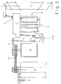
- FIG. 1 shows an agricultural working machine with a drive according to the present invention, in a schematic side view
- FIG. 2 shows a detailed view of the drive according to the present invention in FIG. 1
- FIG. 3 shows a schematic illustration of the hydraulic circuit that is the drive according to the present invention
- FIG. 4 shows a detailed longitudinal sectional view of the valve system according to the present invention
- FIG. 1 shows an agricultural working machine 1 designed as a self-propelled forage harvester 2 , to the front region of which a front attachment 3 designed as a pick-up 4 is assigned.
- front attachment 3 picks up a crop-material strand 6 lying on ground 5 using a pick-up device 7 , compresses it using a hold-down system 8 , and subsequently guides crop-material strand 6 via a cross auger component 9 to intake and pre-compression rollers 10 located downstream of front attachment 3 .
- Intake and pre-compression rollers 10 are retained, in pairs, in a feeder housing 11 .
- the pairs of intake and pre-compression rollers 10 are driven actively in the direction of arrow 12 using a drive 13 to be described below in greater detail.
- compressed crop-material strand 6 enters the working region of cutter blade 15 of an actively driven, rotating chopper drum 16 .
- Chopped crop-material strand 6 subsequently exits the rear region of chopper drum at a high rate of speed and enters a rising lower discharge chute 17 , in which crop-material strand 6 is conveyed, using a “post-accelerator” 18 in some cases, out of forage harvester 2 to a forage vehicle, which is not shown.
- a foreign-object detection device 12 known per se is assigned to intake roller pair 20 located on the front. If foreign object 19 located in crop-material strand 6 is conveyed into the vicinity of foreign-object detection device 21 , it generates a position-detection signal X, which is supplied to an evaluation and control unit 22 and, in this, generates a “quick stop” signal Y that switches off drive 13 (to be described below in greater detail) of intake and pre-compression rollers 10 .
- operator 23 of agricultural working machine 1 can trigger, via an input terminal 24 , a reversing signal Z in evaluation and control unit 22 , which triggers a reversing operation of drive 13 and intake and pre-compression rollers 10 coupled with it.
- Detected foreign object 19 can be conveyed out of the vicinity of intake and pre-compression rollers 10 and can eventually be removed from crop-material strand 6 by operator 23 .
- An automatic triggering of the reversing procedure described above after intake and pre-compression rollers 10 come to a standstill also lies within the scope of the present invention.
- a first drive-belt system 25 transfers the drive energy of motor 26 to chopper drum 16 , among other things, from which a further belt system 27 drives a hydraulic motor-pump unit 28 , which ultimately forms stepless hydraulic drive 13 of intake and pre-compression rollers 10 .
- a mechanical transfer gearbox 31 is assigned to output shaft 29 of motor-pump unit 28 via a universal drive shaft 30 , mechanical transfer gearbox 31 initially driving each of the intake and pre-compression rollers 10 in a manner known per se.
- transfer gearbox 31 includes a further gearbox outlet 32 , which directly drives cross auger component 9 of front attachment 3 located in front of intake and pre-compression rollers 12 .
- cross auger component 9 of front attachment 3 can now also be integrated in the quick-stop function (which will be described in greater detail, below) and in the reversing procedure of intake and pre-compression rollers 10 .
- the rest of the actively driven units 7 , 8 of particular front attachment 3 are driven via a further mechanical drive, which is not shown.
- FIG. 3 shows motor-pump unit 28 in a schematic, detained illustration.
- Hydromotor 40 and hydropumpe 41 are interconnected via a line system 42 in which switching valve system 44 , according to the present invention, designed as proportionally servo valve 43 is integrated.
- Motor-pump unit 28 is also integrated in a hydraulic circuit 45 that includes a hydraulic pump 46 designed as a pressure source in a manner known per se, a tank 47 for storing the hydraulic medium, and a pressure reservoir 48 . Due to available external pressure source 46 , hydraulic circuit 45 functions as a constant-pressure circuit in a manner known per se. Further electrohydraulic switching valves 49 - 51 integrated in hydraulic circuit 45 and the mode of operation of hydraulic circuit 45 are described in greater detail with reference to the simplified, longitudinal sectional drawing of switching valve system 44 according to the present invention, in FIG. 4 .
- hydraulic circuit 45 can enable an abrupt halt of intake conveyor mechanisms designed as intake and pre-compression rollers 10 .
- at least hydromotor 40 , hydropump 41 and required switching valves 43 , 49 - 51 are all located in a drive block 33 which forms drive 13 , individual elements 40 , 41 , 43 , 49 - 51 of hydraulic circuit 45 being interconnected directly using flanges and/or via a piping network.
- switching valves 43 , 49 - 51 of hydraulic circuit 45 are switched in an electrohydraulic manner.
- a design of this type has the advantage, in particular, that no hose lines or valve controls based on the use of spring force are located, at the least, in the region of hydraulic circuit 45 that realizes the braking of drive 13 , the elastic properties of the hose lines and/or valve controls—e.g., the pressure-dependent expansion of hose lines and the inertia of systems based on the use of spring force—would stand in the way of an abrupt braking of drive 13 of intake and pre-compression rollers 10 .
- Proportionally servo valve 43 as shown in FIG. 4 , has housing sections 52 , 53 at its ends, which are penetrated by bores 54 in which control cylinders 55 , 56 are displaceably located, the movement of control cylinders 55 , 56 being limited by terminal stops 57 .
- control cylinders 55 , 56 accommodate a piston surface 58 between them, via which a displacement of control cylinders 55 , 56 also results in a displacement of valve piston 59 inside proportionally servo valve 43 .
- control cylinders 55 , 56 are acted upon, independently of each other, in their rear regions via control-pressure lines 60 with a defined control pressure, which holds valve piston 59 state of equilibrium as shown in FIG. 4 .
- the circulation of the hydraulic medium between hydromotor 40 and hydropump 41 is closed.
- the hydraulic medium is pumped to hydromotor 40 via a pressure line 61 , and is returned via a return line 62 , then it is pumped back to hydromotor 40 by hydropumpe 41 .
- a partial quantity of the hydraulic medium is removed from circulation via an exchange portion of oil-channel 63 to be cooled and/or filtered. It is within the scope of the present invention for the equilibrium between control cylinders 55 , 56 to be realized using matched cylinder-surface designs or by applying pressure to control cylinders 55 , 56 using controlled oil pressures.
- the “normal operation” operating state is maintained until a foreign object 19 is detected at the foreign-object detection device 21 , quick-stop signal Y is generated in evaluation and control unit 22 , and the system switches to the “quick stop” operating state.
- Quick-stop signal Y causes quick-stop switching valve 49 assigned to proportionally servo valve 43 to be switched to the position shown in FIG. 3 .
- upper control cylinder 56 is depressurized by removing the hydraulic medium via pressure line 60 and quick-stop switching valve 49 assigned thereto and directing it into tank 47 .
- upper control cylinder 56 functions as an opening cylinder.
- lower control cylinder 55 which is also pressurized, functions as a closing cylinder and moves valve piston 59 in the direction of arrow 65 using proportionally servo valve 43 according to the present invention.
- lower control cylinder 55 In its front region assigned to piston surface 58 of valve piston 59 , lower control cylinder 55 accommodates a by-pass piston 66 , which is penetrated by by-pass bores 67 .
- a first step the motion of lower control cylinder 55 displaces by-pass piston 66 into the region of pressure line 61 leading to hydromotor 40 .
- the hydraulic medium by-passes hydromotor 40 via a by-pass line 64 and returns to hydropump 41 , causing the supply of pressurized hydraulic medium to hydromotor 40 to be interrupted, which also causes hydromotor 40 to be shut off.
- the continued motion of valve piston 59 in the direction of arrow 65 closes exchange portion of oil-channel 63 via a restrictor 68 integrally moulded on valve piston 59 , thereby preventing additional hydraulic medium from being conducted away via exchange portion of oil-channel 63 .
- valve piston 59 closes return line 62 from hydromotor 40 to hydropump 41 . Since hydropump 41 continues to pump hydraulic medium to hydromotor 40 , but hydraulic medium can no longer flow out, a banking-up pressure abruptly forms in pressure line 61 to hydromotor 40 , which abruptly halts hydromotor 40 and intake and pre-compression rollers 10 coupled therewith.
- valve piston 59 assigned to control cylinder 56 functioning as an opening cylinder is penetrated by restrictor slits 69 , via which the excess hydraulic medium can flow out of motor return line 62 .
- restrictor slits 69 , control cylinders 55 , 56 and valve piston 59 are sized such that a banking-up pressure is created which is in the range of the operating pressure of hydraulic circulation and is preferably 350 bar.
- the motion of closing cylinder 55 in the direction of arrow 65 also results in a continual shrinking of the passage cross-section of restrictor slit 69 .
- the differential surface of valve piston 59 is sized such that valve piston 59 with the pressurized closing cylinder 55 is in a state of equilibrium when the banking-up pressure has reached a defined value, e.g., 350 bar in the exemplary embodiment shown. It is thereby ensured, in a simple manner, that the braking function will be reliably maintained.
- a return valve 70 is assigned to valve piston 59 of proportionally servo valve 43 according to the present invention in the form of a sealing disk 73 , which is capable of being moved by the hydraulic medium.
- Sealing disk 73 is located, in a freely movable manner, between the piston surface of valve piston 59 contacted by control cylinders 55 , 56 and a set collar 74 fit into valve piston 59 , and is pressed against set collar 74 or valve piston 59 , depending on the direction of flow of the hydraulic medium.
- Return valve 70 is closed in the “normal operation” operating state, since the hydraulic medium flowing back from hydromotor 40 to hydropump 41 via return line 62 applies pressure to sealing disk 73 in the direction of the piston surface of valve piston 59 and, therefore, in the closing direction.
- hydropump 46 which functions as a pressure source, pumps a pressure-oil flow in the opening direction of return valve 70 —sealing disk 73 bearing against set collar 74 in the opening direction—thereby ensuring that the control-oil flow produced by hydropump 46 during the “quick stop” operating mode reaches hydraulic circuit 45 according to the present invention, thereby ensuring that the accumulated pressure is also maintained in hydraulic circuit 45 during the braking procedure.
- a brake valve 51 designed as an electrohydraulic switching valve can also be assigned to hydropump 41 , which brakes a chopper drum 16 coupled with hydropump 41 via an external drive 71 after the drive of chopper drum 16 is shut off.
- the main effect of this is that long after-running times of shut-off chopper drum 16 are prevented.
- the braking function can be triggered, e.g., by the fact that pressure-source switching valve 50 switches brake valve 51 via a control pressure into the locked position, thereby blocking the rotational motion of hydropump 41 and abruptly braking chopper drum 16 until it comes to a standstill.
- a restrictor cross section 72 is assigned, on the top side, to control cylinder 56 designed as an opening cylinder, via which the hydraulic medium displaced by control cylinder 56 is conducted away.
- control cylinder 56 is braked before it reaches stop 57 assigned to it and allows it to come to rest against stop 57 in a non-abrupt manner.
Landscapes
- Engineering & Computer Science (AREA)
- General Engineering & Computer Science (AREA)
- Mechanical Engineering (AREA)
- Life Sciences & Earth Sciences (AREA)
- Environmental Sciences (AREA)
- Fluid-Pressure Circuits (AREA)
- Lifting Devices For Agricultural Implements (AREA)
- Guiding Agricultural Machines (AREA)
- Catching Or Destruction (AREA)
- Harvester Elements (AREA)
Applications Claiming Priority (2)
| Application Number | Priority Date | Filing Date | Title |
|---|---|---|---|
| DE102005023047A DE102005023047A1 (de) | 2005-05-13 | 2005-05-13 | Einzugsorgansteuerung für landwirtschaftliche Arbeitsmaschine |
| DE102005023047.4 | 2005-05-13 |
Publications (2)
| Publication Number | Publication Date |
|---|---|
| US20060254235A1 US20060254235A1 (en) | 2006-11-16 |
| US7464525B2 true US7464525B2 (en) | 2008-12-16 |
Family
ID=36586158
Family Applications (1)
| Application Number | Title | Priority Date | Filing Date |
|---|---|---|---|
| US11/430,777 Expired - Fee Related US7464525B2 (en) | 2005-05-13 | 2006-05-09 | Intake conveyor mechanism control for an agricultural working machine |
Country Status (4)
| Country | Link |
|---|---|
| US (1) | US7464525B2 (de) |
| EP (1) | EP1721518B1 (de) |
| AT (1) | ATE443436T1 (de) |
| DE (2) | DE102005023047A1 (de) |
Cited By (7)
| Publication number | Priority date | Publication date | Assignee | Title |
|---|---|---|---|---|
| US20080295471A1 (en) * | 2007-05-30 | 2008-12-04 | Manfred Pollklas | Agricultural harvesting machine with a foreign-object detection device |
| US20100011727A1 (en) * | 2008-07-18 | 2010-01-21 | Gkn Walterscheid Gmbh | Drive Arrangement For An Agricultural Machine |
| US20120067037A1 (en) * | 2008-07-11 | 2012-03-22 | Stefan Bohrer | Drive System For An Infeed Conveyor Of A Harvester |
| US20140162738A1 (en) * | 2012-08-07 | 2014-06-12 | Linde Hydraulics Gmbh & Co. Kg | Drive System For Driving A Chopper And Feeder Device Of A Harvesting Machine |
| US20150197398A1 (en) * | 2012-10-11 | 2015-07-16 | Putzmeister Engineering Gmbh | Hydraulic drive system and method for driving a belt conveyor |
| US20160032817A1 (en) * | 2014-08-04 | 2016-02-04 | Jeffrey J. Buschur | Power conversion device |
| US20160302360A1 (en) * | 2013-12-16 | 2016-10-20 | Cnh Industrial America Llc | Crop Pick-Up, Agricultural Equipment and Method of Ejecting a Foreign Object |
Families Citing this family (7)
| Publication number | Priority date | Publication date | Assignee | Title |
|---|---|---|---|---|
| DE102008002428A1 (de) | 2008-06-13 | 2009-12-17 | Deere & Company, Moline | Antriebssystem für eine Erntemaschine |
| DE102009035571A1 (de) * | 2009-07-31 | 2011-02-03 | Hydac System Gmbh | Hydrostatischer Antrieb |
| GB2479566A (en) * | 2010-04-15 | 2011-10-19 | Agco Int Gmbh | Braking system for a rotating chopper drum of a forage harvester |
| US9510514B2 (en) * | 2015-04-14 | 2016-12-06 | Deere & Company | Lockout closure mechanism for agricultural vehicle |
| CN106922318A (zh) * | 2017-02-17 | 2017-07-07 | 山东省农业机械科学研究院 | 生物质粉碎机 |
| EP4066621A1 (de) * | 2021-03-31 | 2022-10-05 | CNH Industrial Belgium N.V. | Selbstfahrender mählader mit mitteln zur verminderung von stutzenverstopfungen |
| EP4449853A1 (de) * | 2023-04-21 | 2024-10-23 | CNH Industrial Belgium N.V. | Steuersystem eines grassaufnahmevorsatzgeräts mit fremdkörpererkennung und entsprechendes steuerverfahren |
Citations (10)
| Publication number | Priority date | Publication date | Assignee | Title |
|---|---|---|---|---|
| US3736753A (en) * | 1971-09-22 | 1973-06-05 | Deere & Co | Hydraulic drive |
| US4918918A (en) * | 1986-11-25 | 1990-04-24 | Daikin Industries, Ltd. | Variable displacement piston machine |
| US5325670A (en) * | 1989-02-10 | 1994-07-05 | Honda Giken Kogyo Kabushiki Kaisha | Clutch control device for transmission |
| US20010037638A1 (en) | 2000-05-04 | 2001-11-08 | Bernard Krone | Harvesting machine, especially a self-propelled pick-up chopper |
| US6324822B1 (en) * | 1999-02-05 | 2001-12-04 | Case Harvesting Systems Gmbh | Method of detecting foreign objects in a harvesting machine |
| DE10036612A1 (de) | 2000-07-27 | 2002-02-14 | Case Harvesting Sys Gmbh | Feldhäcksler mit hydraulisch angetriebenen Einzugsorganen |
| US6397570B1 (en) * | 1999-11-20 | 2002-06-04 | Deere & Company | Stopping device for a crop transport mechanism |
| US6564549B2 (en) * | 2000-06-05 | 2003-05-20 | Komatsu Ltd. | Displacement control device for hydraulic pump and brake control device for hydraulic motor |
| US20030172638A1 (en) * | 2000-03-06 | 2003-09-18 | Ameye Danny R | Feeder controls for a forage harvester |
| US7022012B2 (en) * | 2004-09-02 | 2006-04-04 | Cnh America Llc | Sensitivity adjustment for stone detection system |
Family Cites Families (3)
| Publication number | Priority date | Publication date | Assignee | Title |
|---|---|---|---|---|
| DE4214204B4 (de) * | 1992-04-30 | 2004-02-05 | Claas Saulgau Gmbh | Antriebsvorrichtung für die Einzugswalzen eines Feldhäckslers |
| US6388860B1 (en) * | 2000-02-17 | 2002-05-14 | Deere & Company | Dual switch control system |
| DE10153019A1 (de) * | 2001-10-26 | 2003-05-08 | Ina Schaeffler Kg | Elektromagnet, insbesondere Proportionalmagnet zur Betätigung eines hydraulischen Ventils |
-
2005
- 2005-05-13 DE DE102005023047A patent/DE102005023047A1/de not_active Withdrawn
-
2006
- 2006-03-03 AT AT06004359T patent/ATE443436T1/de active
- 2006-03-03 EP EP06004359A patent/EP1721518B1/de not_active Expired - Lifetime
- 2006-03-03 DE DE502006004898T patent/DE502006004898D1/de not_active Expired - Lifetime
- 2006-05-09 US US11/430,777 patent/US7464525B2/en not_active Expired - Fee Related
Patent Citations (12)
| Publication number | Priority date | Publication date | Assignee | Title |
|---|---|---|---|---|
| US3736753A (en) * | 1971-09-22 | 1973-06-05 | Deere & Co | Hydraulic drive |
| US4918918A (en) * | 1986-11-25 | 1990-04-24 | Daikin Industries, Ltd. | Variable displacement piston machine |
| US5325670A (en) * | 1989-02-10 | 1994-07-05 | Honda Giken Kogyo Kabushiki Kaisha | Clutch control device for transmission |
| US6324822B1 (en) * | 1999-02-05 | 2001-12-04 | Case Harvesting Systems Gmbh | Method of detecting foreign objects in a harvesting machine |
| US6397570B1 (en) * | 1999-11-20 | 2002-06-04 | Deere & Company | Stopping device for a crop transport mechanism |
| US20030172638A1 (en) * | 2000-03-06 | 2003-09-18 | Ameye Danny R | Feeder controls for a forage harvester |
| US20010037638A1 (en) | 2000-05-04 | 2001-11-08 | Bernard Krone | Harvesting machine, especially a self-propelled pick-up chopper |
| DE10021663A1 (de) | 2000-05-04 | 2001-11-15 | Krone Bernhard Gmbh Maschf | Erntemaschine, insbesondere selbstfahrender Feldhäcksler |
| US6510679B2 (en) | 2000-05-04 | 2003-01-28 | Maschinenfabrik Bernard Krone Gmbh | Harvesting machine, especially a self-propelled pick-up chopper |
| US6564549B2 (en) * | 2000-06-05 | 2003-05-20 | Komatsu Ltd. | Displacement control device for hydraulic pump and brake control device for hydraulic motor |
| DE10036612A1 (de) | 2000-07-27 | 2002-02-14 | Case Harvesting Sys Gmbh | Feldhäcksler mit hydraulisch angetriebenen Einzugsorganen |
| US7022012B2 (en) * | 2004-09-02 | 2006-04-04 | Cnh America Llc | Sensitivity adjustment for stone detection system |
Cited By (14)
| Publication number | Priority date | Publication date | Assignee | Title |
|---|---|---|---|---|
| US7721515B2 (en) * | 2007-05-30 | 2010-05-25 | Claas Selbstfahrende Erntemaschinen Gmbh | Agricultural harvesting machine with a foreign-object detection device |
| US20080295471A1 (en) * | 2007-05-30 | 2008-12-04 | Manfred Pollklas | Agricultural harvesting machine with a foreign-object detection device |
| US20120067037A1 (en) * | 2008-07-11 | 2012-03-22 | Stefan Bohrer | Drive System For An Infeed Conveyor Of A Harvester |
| US8869522B2 (en) * | 2008-07-11 | 2014-10-28 | Deere & Company | Drive system for an infeed conveyor of a harvester |
| US7950209B2 (en) * | 2008-07-18 | 2011-05-31 | Gkn Walterscheid Gmbh | Drive arrangement for an agricultural machine |
| US20100011727A1 (en) * | 2008-07-18 | 2010-01-21 | Gkn Walterscheid Gmbh | Drive Arrangement For An Agricultural Machine |
| US20140162738A1 (en) * | 2012-08-07 | 2014-06-12 | Linde Hydraulics Gmbh & Co. Kg | Drive System For Driving A Chopper And Feeder Device Of A Harvesting Machine |
| US9398744B2 (en) * | 2012-08-07 | 2016-07-26 | Linde Hydraulics Gmbh & Co. Kg | Drive system for driving a chopper and feeder device of a harvesting machine |
| US20150197398A1 (en) * | 2012-10-11 | 2015-07-16 | Putzmeister Engineering Gmbh | Hydraulic drive system and method for driving a belt conveyor |
| US9463933B2 (en) * | 2012-10-11 | 2016-10-11 | Putzmeister Engineering Gmbh | Hydraulic drive system and method for driving a belt conveyor |
| US20160302360A1 (en) * | 2013-12-16 | 2016-10-20 | Cnh Industrial America Llc | Crop Pick-Up, Agricultural Equipment and Method of Ejecting a Foreign Object |
| US9936642B2 (en) * | 2013-12-16 | 2018-04-10 | Cnh Industrial America Llc | Crop pick-up, agricultural equipment and method of ejecting a foreign object |
| US20160032817A1 (en) * | 2014-08-04 | 2016-02-04 | Jeffrey J. Buschur | Power conversion device |
| US9915192B2 (en) * | 2014-08-04 | 2018-03-13 | Jeffrey J. Buschur | Power conversion device |
Also Published As
| Publication number | Publication date |
|---|---|
| DE502006004898D1 (de) | 2009-11-05 |
| EP1721518B1 (de) | 2009-09-23 |
| US20060254235A1 (en) | 2006-11-16 |
| EP1721518A1 (de) | 2006-11-15 |
| ATE443436T1 (de) | 2009-10-15 |
| DE102005023047A1 (de) | 2007-01-18 |
Similar Documents
| Publication | Publication Date | Title |
|---|---|---|
| US7464525B2 (en) | Intake conveyor mechanism control for an agricultural working machine | |
| US5086613A (en) | Check-relief valve for a hydraulic circuit | |
| CN102016259B (zh) | 液压风扇换向阀及使用该换向阀的机器 | |
| KR100742253B1 (ko) | 유압펌프의 용량제어장치 및 유압모터의 브레이크 제어장치 | |
| US9732773B2 (en) | Drive system for hydraulically driven working mechanisms of a working machine | |
| CA1073739A (en) | Hydraulic pump control system | |
| US3750406A (en) | Servo-control device for varying the delivery and direction of distribution of a variable delivery pump | |
| US9398744B2 (en) | Drive system for driving a chopper and feeder device of a harvesting machine | |
| CN110094377A (zh) | 具有用于能量回收的液压装置的作业机械 | |
| EP3061976B1 (de) | Eine landwirtschaftliche erntemaschine | |
| EP1847170B1 (de) | Rotorumkehrmechanismus | |
| EP4466975A1 (de) | Konditionierwalzensystem für eine erntemaschine | |
| EP1606518B1 (de) | Anordnung zur steuerung eines hydraulisch angetriebenen motors | |
| US4329845A (en) | Augmented charging system for a hydrostatic transmission | |
| US4032260A (en) | Hydraulic control device | |
| US7487706B2 (en) | Device for controlling a hydraulically driven motor | |
| US12532809B2 (en) | Conditioning roll tension control by header drive pressure | |
| US20240276917A1 (en) | Forage Harvesters | |
| SU1011403A1 (ru) | Гидравлическое устройство дл торможени колесных машин с гидроприводом | |
| JPH08296604A (ja) | ブレーキ弁用リリーフ弁 | |
| US20040057836A1 (en) | Hydraulic pump circuit | |
| JPS63235702A (ja) | 油圧モ−タの制御装置 | |
| JPS63243504A (ja) | 2速油圧モータの制御装置 | |
| CA2035290A1 (en) | Check-relief valve for a hydraulic circuit | |
| PL158329B1 (en) | Hydraulic driving and control unit of wheel scraper |
Legal Events
| Date | Code | Title | Description |
|---|---|---|---|
| AS | Assignment |
Owner name: CLAAS SELBSTFAHRENDE ERNTEMASCHINEN GMBH, GERMANY Free format text: ASSIGNMENT OF ASSIGNORS INTEREST;ASSIGNORS:DUECKINGHAUS, HEINZ;STRIEKER, NORBERT;RHODY, THOMAS;REEL/FRAME:017883/0473;SIGNING DATES FROM 20060424 TO 20060426 |
|
| FEPP | Fee payment procedure |
Free format text: PAYOR NUMBER ASSIGNED (ORIGINAL EVENT CODE: ASPN); ENTITY STATUS OF PATENT OWNER: LARGE ENTITY |
|
| FPAY | Fee payment |
Year of fee payment: 4 |
|
| REMI | Maintenance fee reminder mailed | ||
| LAPS | Lapse for failure to pay maintenance fees | ||
| STCH | Information on status: patent discontinuation |
Free format text: PATENT EXPIRED DUE TO NONPAYMENT OF MAINTENANCE FEES UNDER 37 CFR 1.362 |
|
| STCH | Information on status: patent discontinuation |
Free format text: PATENT EXPIRED DUE TO NONPAYMENT OF MAINTENANCE FEES UNDER 37 CFR 1.362 |
|
| FP | Lapsed due to failure to pay maintenance fee |
Effective date: 20161216 |