US7474777B2 - Device and method for optical measurement of chemical and/or biological samples - Google Patents
Device and method for optical measurement of chemical and/or biological samples Download PDFInfo
- Publication number
- US7474777B2 US7474777B2 US10/476,243 US47624304A US7474777B2 US 7474777 B2 US7474777 B2 US 7474777B2 US 47624304 A US47624304 A US 47624304A US 7474777 B2 US7474777 B2 US 7474777B2
- Authority
- US
- United States
- Prior art keywords
- detector
- partial area
- image field
- sample
- optical measurement
- Prior art date
- Legal status (The legal status is an assumption and is not a legal conclusion. Google has not performed a legal analysis and makes no representation as to the accuracy of the status listed.)
- Expired - Lifetime, expires
Links
Images


Classifications
-
- G—PHYSICS
- G02—OPTICS
- G02B—OPTICAL ELEMENTS, SYSTEMS OR APPARATUS
- G02B21/00—Microscopes
- G02B21/18—Arrangements with more than one light path, e.g. for comparing two specimens
-
- G—PHYSICS
- G01—MEASURING; TESTING
- G01N—INVESTIGATING OR ANALYSING MATERIALS BY DETERMINING THEIR CHEMICAL OR PHYSICAL PROPERTIES
- G01N21/00—Investigating or analysing materials by the use of optical means, i.e. using sub-millimetre waves, infrared, visible or ultraviolet light
- G01N21/62—Systems in which the material investigated is excited whereby it emits light or causes a change in wavelength of the incident light
- G01N21/63—Systems in which the material investigated is excited whereby it emits light or causes a change in wavelength of the incident light optically excited
-
- G—PHYSICS
- G02—OPTICS
- G02B—OPTICAL ELEMENTS, SYSTEMS OR APPARATUS
- G02B21/00—Microscopes
- G02B21/0096—Microscopes with photometer devices
Definitions
- the invention relates to a device and a method for optical measurement of chemical and/or biological samples.
- the inventive device and the inventive method are particularly suited for use in high and medium throughput screening systems.
- image measurements generally, the value of a physical quantity is recorded in dependence on the measurement site.
- the measurement of this physical quantity is performed either at numerous different points or measurement sites in parallel, or respectively only at one point, and the site of this point, i.e. the measurement site, will be varied.
- the latter is often referred to as a “screening” of the sample surface.
- each individual measurement has to be performed very fast so that the image measurement can be concluded within an acceptable length of time.
- Examples of useful image measurement methods are: bright-field, dark-field, total-internal-reflection, fluorescence, 2-photon-fluorescence, fluorescence-lifetime, fluorescence-emission-spectroscopy, polarization and fluorescence-polarization microscopy. Further, these methods can be performed by use of different detectors such as e.g. line cameras or surface cameras, and, in part, these detectors can be used both in conventional and confocal arrangements.
- the measurement is carried out only at one site on the sample, or the site information is not evaluated, or an averaging including a large number of measurement sites is performed (conventional measurement by use of a large-surfaced detector).
- the individual measurement may be both more complex and more time-consuming.
- the complexity can relate both to the measurement apparatus and the data obtained (e.g. complete spectra). For instance, in the fluorescence correlation spectroscopy (FCS) point measurement method, the fluctuation of a fluorescence signal coming from a small volume is recorded over a longer period of time, and the signal is used to derive information on photophysical, chemical and physical properties of fluorescent particles and molecule in this volume.
- FCS fluorescence correlation spectroscopy
- a sample can be subjected to imaging measurement methods for performing a plurality of measurements of the same sample region under different measurement conditions or with different detectors. Thereby, for instance, there is determined the distribution of different fluorophobes in the sample, which differ from each other with regard to their photophysical properties such as e.g. the excitation and emission spectra and/or the fluorescence lifetime.
- FCS apparatus for intracellular FCS by Brock (see e.g. Brock, “Fluorescence Correlation Microscopy and Quantitative Microsphere Recruitment Assay”, dissertation, 1999).
- This apparatus comprises a fluorescence microscope which has been retrofitted to include the components required for FCS.
- the selection among the measurement methods of microscopy or FCS is realized by a hinged mirror arranged in the path of rays.
- LSM laser scanning microscopes
- the first filter determines the excitation wavelength range
- the second filter is a dichromatic mirror which reflects the excitation light and transmits the emission light (or vice versa).
- a further filter is inserted, transmitting only the emission range.
- a single filter set can be arranged for a plurality of colorants if the excitation and emission wavelengths are sufficiently remote from each other, as is the case e.g. for the colorants DAPI, FITC and TRITC.
- a color film or a color CCD camera can be used.
- a monochrome camera in combination with a selectable excitation spectrum, as performed e.g. in the so-called Pinkel filter sets. Filter sets also offer the opportunity to distinguish colorants from each other on the basis of their Stokes shift. In this manner, different colorants can be excited by the same wavelength and will differ from each other by the different displacement of the emission spectrum.
- imaging spectrographs are not particularly suited to record an image of the sample because the recording times—and possibly also the processing times—are frequently as long as several seconds.
- an optical measurement device for measurement of chemical and/or biological samples, particularly for use in high throughput screening systems, including: an optical means ( 22 ) for imaging a sample area in an image filed ( 10 ), a first detector ( 28 ) covering a first partial area ( 12 ) of the image field ( 10 ), and a second detector ( 34 ) covering a second partial area ( 14 ) of the image field ( 10 ).
- the above object is achieved by the features of an optical measurement device according to the previous embodiment, further characterized in that one of the detectors ( 28 , 34 , 42 ) is arranged as a focusing means ( 70 ) for axial fixation of the sample area imaged in the image field ( 10 ).
- an optical measurement device for measurement of chemical and/or biological samples ( 20 ), particularly for use in high throughput screening systems, including: an optic means ( 22 ) for imaging a spatially restricted sample area in a spatially restricted image field ( 10 ), a first detector ( 28 ) covering a first partial area ( 12 ) of the image field ( 10 ), and a focusing means ( 70 ) for axial fixation of the sample area imaged in the image field ( 10 ), comprising a light source ( 72 ) generating a focusing beam, the focusing beam extending at least partially within the path of rays ( 30 ) generating the image field ( 10 ), wherein the illumination means ( 16 ) generates the focusing beam.
- the invention is based on the recognition that, when imaging a sample area, an image field will always include a part that is not used for examination.
- a round image field 10 ( FIG. 1 ) is generated.
- the image field e.g. within a first partial area 12 of the image field 10 .
- the field of a CCD camera is arranged within the image field, e.g. within a first partial area 12 of the image field 10 .
- the part of the image field 10 surrounding the first partial area 12 is thus not utilized for the detection of reactions occurring in the sample.
- the core of the invention resides in that a second partial area of the image field in the unused area of the image field is covered by a second detector.
- the inventive optical measurement device which is particularly suited for use in high-throughput screening systems can comprise an illumination unit for illuminating the sample undergoing measurement. Further, an optical device is provided for imaging a sample area in the image field. Further provided is a first detector covering a first partial area of the image field. According to the invention, a second detector is provided which covers the second partial area of the image field.
- the first detector as a CCD camera which is used to perform one of the above described image measurement methods.
- a second detector there is preferably performed a point measurement method by which e.g. the development over time of a signal can be recorded.
- the provision of a tiltable mirror for switching between the different detectors used for different measurement methods is not required.
- no mechanical wear can occur which might affect the measurement results, particularly the relative position of the two measurement areas in the sample.
- the switching process i.e. the tilting of the mirror, so that the required measurements can be performed in shorter period of time.
- This is advantageous particularly in case of extremely expensive methods such as high throughput screening.
- the possibility of simultaneously performing two different measurements on a sample offers the further advantage that effects in a sample which occur only for a short time can be observed also by two measurement methods. When using known devices, the two different measurements have to be carried out successively on two samples.
- a spatially limited outcoupling of at least one partial area of an image field is realized preferably by a totally reflecting mirror wherein the outcoupled partial area is covered by a point detector such as e.g. a fiber end.
- the inventive device is particularly suited for application in medium and high throughput screening methods, the device is preferably used to observe individual wells of sample carriers such as titration plates and the like.
- the device will generate an image of a part of the liquid contained in a well while a partial area of this well image is outcoupled.
- a totally reflecting mirror for outcoupling the partial area it is thus possible to detect different areas of the image by use of different detectors, e.g. surface and point detectors.
- no tiltable mirror or dichroic mirror has to be provided. This is advantageous in that, one the one hand, no mechanical wear and the like will occur, and, on the other hand, no expensive dichroic mirror need be used.
- a multi-channel microscopy can be performed in a simple manner. Since the different parts of the image field can be deflected, e.g. by providing mirrors, it is made possible to arrange different filters in the individual paths of rays. The need for an exchange of filters is obviated. Further, filters specially attuned to the requirements can be inserted in the two paths of rays. A provision of expensive combination filters and the like is not required. Further, a considerably larger number of colorants can be used since the latter need not be adapted anymore to a special filter system.
- the separation of the two partial areas is not performed on the basis of spectral differences by means of dichromatic mirrors, or sequentially over time by tilting a mirror inwards and outwards.
- the first detector is arranged on the optical axis of an objective of the optics unit.
- a mirror Arranged in the peripheral region of the path of rays generating the image field is a mirror used to outcouple the second partial area and to direct the same to the second detector.
- This offers the advantage that the second detector does not have to be arranged immediately beside the first detector.
- different detectors can be used which would possibly not allow for an arrangement of two detectors immediately side by side, e.g. because a control element of the detector and the like is arranged next to the detector surface.
- the first detector not directly on the axis of the objective but, instead, to deflect also the path of rays by means of mirrors.
- the path of rays generating the image field has arranged therein a mirror for outcoupling the second partial area.
- the mirror is arranged to lie outside the path of rays covered by the first detector.
- an overlapping of the individual partial regions is avoided. Since it is safeguarded by the position of the mirror outcoupling the second partial area that this mirror does not extend into the path of rays directed onto the first detector, preferred use can be made of a totally reflecting mirror. Thus, advantageously, the mirror will not affect the radiation detected by the second detector.
- the remaining image field can be used by a plurality of detectors.
- the image field is divided into a number of two, three, four or more partial regions. Each of these partial regions in turn can be outcoupled via a mirror. Consequently, problems caused by restricted space will be avoided.
- the further detectors, or the further mirrors for provided to outcouple corresponding partial regions for these detectors are arranged in such a manner that an overlapping of the partial regions is excluded.
- At least one of the detectors is designed as a point detector.
- This detector can be provided e.g. as the open fiber end of an optic fiber.
- Such a point sensor is useful e.g. for the measurement of the development over time of the fluorescence of material.
- the axial position of the measurement point be reproducibly settable.
- the axial adjustment i.e. the focusing
- the axial adjustment has to be performed automatically and quickly. No intervention of operating personal is required because this would occupy too much time and render the high throughput screening methods uneconomical. Since the quality of the received signal is considerably dependent on the axial position, it will normally be necessary to repeat the focusing for each sample under examination.
- the inventive device For focusing, it is possible to use or statistically evaluate the changes in contrast of an image recorded by the detector.
- one of the detectors as a focusing means for axial fixation of the sample area imaged in the image field. Therefore, one of the detectors on which a partial area of the image field is imaged can be used for focusing. This offers the advantage that no additional focusing means are required; such means would normally need a separate light source which would influence the measurement results because this light source would also insert light into the sample.
- active focusing means which can then have a light source of their own to direct light into the sample for focusing.
- a light beam obliquely entering the sample to thus generate a fluorescence line in the fluorescing sample.
- the reflection of this obliquely incident light beam can be used for focusing.
- a corresponding device is described e.g. in U.S. Pat. No. 6,025,601.
- Such focusing by means of a line incident on the sample is not useful particularly in case of brightly fluorescing samples.
- the excitation power used should be as small as possible to avoid a bleaching of the sample and possible damage of living cells which may exist in the sample.
- a focusing means with aperture stop is used.
- the aperture stop By means of the aperture stop, a point of the smallest possible size is illuminated in the sample. The light reflected by this point passes through the same aperture stop to be incident on a detector. Because of the confocality of the arrangement, a focusing is obtained only if a reflecting face in the sample is arranged in the position corresponding to the aperture. If, for instance, the reflection occurs on a glass bottom of a sample carrier having the samples arranged therein, the inventive device allows the focusing onto the glass bottom to be performed in a simple manner.
- the plane having the aperture stop arranged therein can be selected to the effect that, in case of a reflection signal from the glass bottom through the aperture, the other detectors are arranged to the effect that their focus will be located in the sample area of interest.
- the invention further relates to an optical measurement device comprising an illumination unit and an optics unit as described above.
- a first partial area of the image field is covered by a first detector.
- a focusing means is provided for axial fixation of the sample area imaged in the image field.
- the focusing means comprises a light source generating a focusing beam, with the focusing beam extending at least partially within the path of rays generating the image field.
- a focusing mirror is provided which is arranged in the image-field path of rays after the manner of the above described mirror.
- the arrangement of the mirror is in turn provided such that the mirror will not intersect with the partial area of the image field observed by the first detector, i.e. will not cast a shadow onto the first detector.
- the focusing means is arranged in such a manner that the optics means will direct the focusing beam towards the sample.
- the focusing beam reflected by the sample or the boundary surface of a sample carrier will be directed by the optics means towards the focusing means and towards the focusing mirror, respectively.
- the reflection of the focusing beam can take place on different boundary surfaces. For instance, the reflection of the outer surface of the sample carrier can occur on the bottom face of the sample carrier, i.e.
- a combination of the two above described devices is possible so that a plurality of detectors are provided for detecting different partial areas of the image field, and further, a focusing means is provided which preferably covers none of the partial areas of the image field but will utilize the optics means for directing the focusing beam.
- the invention further relates to a method for optical measurement of chemical and/or biological samples, particularly by means of high throughput screening systems.
- the sample to be measured can be illuminated.
- an optics means a sample area is imaged in an image field. Both the sample area and the image field are spatially limited regions.
- a first partial area of the image field the image which is imaged in the partial area is taken up by a first detector.
- a second partial area of the image field is taken up by a second detector.
- the inventive method not only two but three, four, five or more partial areas are of the image field are covered.
- the individual partial areas will preferably not overlap.
- FIG. 1 is a schematic view of an image field
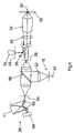
- FIG. 2 is a schematic view of a preferred embodiment of the invention with three detectors
- FIGS. 3-5 are schematic views of possible arrangements of the second detector
- FIGS. 6-8 are schematic views of possible configurations of the first detector together with an illumination means
- FIG. 9 is a schematic view of a further preferred embodiment of the invention in combination with a focusing means.
- FIG. 1 shows an image field 10 as normally generated in an optics means used in microscopes and the like.
- image field 10 is provided as a circular two-dimensional region.
- a first partial area 12 is provided within image field 10 .
- the first partial area 12 is a rectangular partial area, e.g. the camera field of a CCD camera.
- a second partial area 14 is also arranged within image field 10 .
- the second partial area 14 is represented as a circle. This is normally a partial area where a point measurement is performed.
- the detector is provided e.g. as an optical fiber so that the partial area 14 has the fiber end of an optical fiber arranged therein.
- the schematic configuration of the inventive optical measurement device ( FIG. 2 ) comprises an illumination means 16 for illuminating a sample 20 arranged e.g. in a titration plate 18 .
- the light emitted from sample 20 or the radiation emitted from sample 20 is guided, by an optics means 22 comprising an objective 24 and at least one tubular lens 26 , in the direction of a first detector 28 .
- the image field 10 . ( FIG. 1 ) is generated.
- the image field is generated by a path of rays 30 marked by hatched lines.
- the first detector 28 covers the first partial area 12 ( FIG. 1 ). The latter is delimited by a first path of rays 32 which is part of the image-field path of rays 30 .
- a second detector 34 provided to cover the second partial area 14 of image field 10 ( FIG. 1 ) is arranged at a rotation of 90° relative to an optical axis 36 .
- a totally reflecting mirror 38 is provided to direct the relevant part of the image-field path of rays 30 towards the second detector 34 .
- Mirror 38 outcouples a part 40 of the image-field path of rays 30 and directs this part to the second detector 34 .
- a further—third—detector 42 can be arranged.
- the third detector 42 is arranged vertically to the optical axis 36 as is the case for the second detector 34 .
- the third partial area of image field 10 imaged on the third detector 42 is outcoupled from the image-field path of rays 30 by a mirror 44 .
- the third detector 42 together with the mirror 44 can also be arranged in a different orientation and cover a different partial area of the image field 10 .
- the path of rays 46 extends between the two mirrors 38 , 44 so that none of the mirrors 38 , 44 can project into the path of rays 46 and thus affect the part of the sample 20 which is imaged onto the first detector 28 .
- the illumination means 16 comprises a light source 50 and a lens arrangement 52 .
- the lens arrangement 52 By the lens arrangement 52 , the light emitted by light source 50 is caused to converge onto the sample so that a concentration of light occurs in the sample 20 .
- the illumination means 16 is arranged opposite the objective unit 22 so that the sample is illuminated from the side opposite the objective unit 22 . This is a case of a so-called transmission illumination. Further, it is possible to illumine the sample 20 by use of incident illumination.
- light emitted by a light source is coupled into the objective 24 by a corresponding lens and mirror arrangement and is directed from the objective into the sample.
- the first detector 28 can be e.g. a CCD or CMOS camera. When combined with a suitable line illumination, the first detector 28 can also be a line camera. Further, the detector can be provided as a spectrograph.
- the second detector use can be made of a detector corresponding to the first detector or a combination of the above described detectors. Further, the possibility exists to provide one or several of the detectors 28 , 34 , 42 e.g. as a fluorescence emission spectroscope, optionally in combination with suitable filters. Further, the detectors can be designed as FCS or FIDA detectors.
- FIGS. 3-5 different possibilities for the arrangement of the second detector 34 are illustrated.
- the illumination means 16 is not shown in these Figures.
- the mirror 38 is located in front of an image plane 54 having the image field 10 arranged therein.
- the deflection of a bundle of rays 40 is performed in the manner described above with reference to FIG. 2 .
- the second detector 34 is arranged in an image plane 56 which is a part of image plane 54 which has been deflected by mirror 38 .
- the mirror 38 in an intermediate image plane 58 ( FIG. 4 ).
- a lens 60 is provided between the mirror 38 and the detector 34 .
- a further lens 62 is provided between the intermediate image plane 58 and the image plane 54 for imaging the first partial area 10 onto the detector 28 . If the detectors 28 , 34 do not require an imaging of the sample (e.g. in case of point intensity measurements or direct coupling into a spectrograph), the lenses 60 , 62 can also be omitted.
- the mirror 38 is also possible to arrange the mirror 38 behind the intermediate image plane 58 when viewed along the path of rays.
- the lens 60 is again arranged between the mirror 38 and the image plane 56 of detector 34 .
- the illumination means 16 is arranged respectively between the intermediate image plane 58 and the image plane 54 .
- the illumination means comprises a lens or lens arrangement 52 .
- the light emitted by the light source 50 which can also be a line illumination means 64 ( FIGS. 7 and 8 ) is coupled, by means of a partially transmitting or dichromatic mirror 66 , into the path of rays extending between the objective 24 and the first detector unit 28 .
- the second detector 34 together with mirror 38 is in each case arranged in front of the intermediate image plane 58 .
- the conventional light source 50 is combined with a CCD or CMOS camera serving as a first detector 28 .
- a line illumination means 64 is provided in combination with a line detector as a first detector 28 .
- the line has to be moved relative to the sample 20 . This is done either by moving the sample or by moving the light beam incident into the sample, e.g. by an oscillating mirror.
- the latter can also be provided as an imaging spectrograph ( FIG. 8 ).
- This spectrograph comprises, apart from an image take-up device 68 , a mirror arrangement including two planar mirrors 69 and a hollow mirror 71 .
- the planar mirrors 69 can be tilted relative to each other.
- a focusing means 70 is provided instead of the second detector 34 .
- one or a plurality of detectors 34 , 42 can be provided in addition to the focusing means 70 .
- Mirror 38 is arranged in the manner described above and particularly evident from FIG. 2 . From a light source 72 , light is guided via a lens 74 to a partially transmitting mirror 76 . From this mirror, the light is deflected towards an aperture stop 78 . The aperture stop is arranged in or near an image plane. Thereby, a point in the sample is illuminated. The light reflected from this point in the sample is directed, again via mirror 38 , towards the aperture stop 78 .
- the light returning from sample 20 is allowed to pass through the partially transmitting mirror 76 and is guided via a lens 80 to a detector 82 .
- a focusing is possible onto a reflecting face of the sample, e.g. a boundary surface of the titration plate or a surface of the sample. With corresponding focusing, a maximum of the light reflected by the sample will pass through the aperture stop and reach the detector 82 . If it is known that a focusing has been performed onto the glass bottom of a sample carrier 18 , the optics unit can then be shifted by a specific amount so that the image field 10 will show an area arranged within the sample. Further, the aperture stop 78 can be moved out of the image plane 56 to such an extent that a signal on detector 82 is accompanied by the focusing of the sample area of interest onto the detector 28 .
- focusing means can be contemplated wherein the focusing is performed e.g. on the basis of the contrast or a fluorescence line generated in the sample.
- the focusing sensors can be provided e.g. as 2 ⁇ 2 phase couplers.
- the fiber itself can be used as the aperture determining the autofocal measurement site.
- an additional aperture stop can be used.
- the measurement point for the autofocus can also be arranged in front of the line when viewed in the scanning direction. In this case, it is possible to carry out the height control, without phase shifting, in a control loop since the measurement point takes up the measurement value at a position which the actual detector will reach only later.
- the outcoupling mirror and the detectors are arranged before, in or behind the image plane.
- the detectors are arranged near the image plane.
Landscapes
- Physics & Mathematics (AREA)
- General Physics & Mathematics (AREA)
- Chemical & Material Sciences (AREA)
- Analytical Chemistry (AREA)
- Health & Medical Sciences (AREA)
- Optics & Photonics (AREA)
- Biochemistry (AREA)
- General Health & Medical Sciences (AREA)
- Life Sciences & Earth Sciences (AREA)
- Immunology (AREA)
- Pathology (AREA)
- Nuclear Medicine, Radiotherapy & Molecular Imaging (AREA)
- Investigating, Analyzing Materials By Fluorescence Or Luminescence (AREA)
- Investigating Or Analysing Materials By The Use Of Chemical Reactions (AREA)
Applications Claiming Priority (4)
| Application Number | Priority Date | Filing Date | Title |
|---|---|---|---|
| DE10121064.7 | 2001-04-28 | ||
| DE10121064A DE10121064A1 (de) | 2001-04-28 | 2001-04-28 | Vorrichtung und Verfahren zur optischen Messung von chemischen und/oder biologischen Proben |
| DE10121064 | 2001-04-28 | ||
| PCT/EP2002/004623 WO2002088819A2 (de) | 2001-04-28 | 2002-04-26 | Vorrichtung und verfahren zur optischen messung von chemischen und/oder biologischen proben |
Publications (2)
| Publication Number | Publication Date |
|---|---|
| US20040257576A1 US20040257576A1 (en) | 2004-12-23 |
| US7474777B2 true US7474777B2 (en) | 2009-01-06 |
Family
ID=7683202
Family Applications (1)
| Application Number | Title | Priority Date | Filing Date |
|---|---|---|---|
| US10/476,243 Expired - Lifetime US7474777B2 (en) | 2001-04-28 | 2002-04-26 | Device and method for optical measurement of chemical and/or biological samples |
Country Status (5)
| Country | Link |
|---|---|
| US (1) | US7474777B2 (de) |
| EP (1) | EP1384104A2 (de) |
| AU (1) | AU2002312858A1 (de) |
| DE (1) | DE10121064A1 (de) |
| WO (1) | WO2002088819A2 (de) |
Cited By (7)
| Publication number | Priority date | Publication date | Assignee | Title |
|---|---|---|---|---|
| US20090074282A1 (en) * | 2007-08-06 | 2009-03-19 | Historx, Inc. | Methods and system for validating sample images for quantitative immunoassays |
| US20100136549A1 (en) * | 2008-09-16 | 2010-06-03 | Historx, Inc. | Reproducible quantification of biomarker expression |
| US20110049388A1 (en) * | 2009-03-02 | 2011-03-03 | Mbio Diagnostics, Inc. | Planar optical waveguide with core of low-index-of-refraction interrogation medium |
| US8120768B2 (en) | 2007-06-15 | 2012-02-21 | Historx, Inc. | Method and system for standardizing microscope instruments |
| US8655037B2 (en) | 2007-05-14 | 2014-02-18 | Historx, Inc. | Compartment segregation by pixel characterization using image data clustering |
| US9212995B2 (en) | 2009-03-02 | 2015-12-15 | Mbio Diagnostics, Inc. | System and method for detecting multiple molecules in one assay |
| US9658222B2 (en) | 2009-03-02 | 2017-05-23 | Mbio Diagnostics, Inc. | Planar waveguide based cartridges and associated methods for detecting target analyte |
Families Citing this family (14)
| Publication number | Priority date | Publication date | Assignee | Title |
|---|---|---|---|---|
| US6937330B2 (en) | 1999-04-23 | 2005-08-30 | Ppd Biomarker Discovery Sciences, Llc | Disposable optical cuvette cartridge with low fluorescence material |
| US6687395B1 (en) | 1999-07-21 | 2004-02-03 | Surromed, Inc. | System for microvolume laser scanning cytometry |
| US6787761B2 (en) | 2000-11-27 | 2004-09-07 | Surromed, Inc. | Median filter for liquid chromatography-mass spectrometry data |
| US6873915B2 (en) | 2001-08-24 | 2005-03-29 | Surromed, Inc. | Peak selection in multidimensional data |
| WO2003095978A2 (en) | 2002-05-09 | 2003-11-20 | Surromed, Inc. | Methods for time-alignment of liquid chromatography-mass spectrometry data |
| DE102004005878A1 (de) * | 2004-02-05 | 2005-09-01 | Rina-Netzwerk Rna Technologien Gmbh | Verfahren zur Überwachung der Herstellung von Biomolekülkristallen |
| US7248360B2 (en) * | 2004-04-02 | 2007-07-24 | Ppd Biomarker Discovery Sciences, Llc | Polychronic laser scanning system and method of use |
| US7276720B2 (en) * | 2004-07-19 | 2007-10-02 | Helicos Biosciences Corporation | Apparatus and methods for analyzing samples |
| US20070070349A1 (en) * | 2005-09-23 | 2007-03-29 | Helicos Biosciences Corporation | Optical train and method for TIRF single molecule detection and analysis |
| JP2007293210A (ja) * | 2006-04-27 | 2007-11-08 | Olympus Corp | イメージング装置 |
| GB2451442B (en) * | 2007-07-30 | 2013-03-06 | Lein Applied Diagnostics Ltd | Optical measurement apparatus and method therefor |
| DE102010015915A1 (de) * | 2010-03-11 | 2011-09-15 | Leica Microsystems Cms Gmbh | Verfahren für einen beschleunigten Anregungswellenlängen-Scan bei einem Fluoreszenzmikroskop |
| DE102010035003B4 (de) * | 2010-08-20 | 2015-08-06 | PicoQuant GmbH. Unternehmen für optoelektronische Forschung und Entwicklung | Räumlich und zeitlich hochauflösende Mikroskopie |
| JP6286863B2 (ja) * | 2013-05-09 | 2018-03-07 | ソニー株式会社 | 光学系、及びテラヘルツ放射顕微鏡 |
Citations (21)
| Publication number | Priority date | Publication date | Assignee | Title |
|---|---|---|---|---|
| US4283112A (en) | 1979-04-24 | 1981-08-11 | Venable Thomas C | Telescope guiding system |
| DE3328821A1 (de) | 1983-08-10 | 1985-02-28 | Fa. Carl Zeiss, 7920 Heidenheim | Autofokus fuer mikroskope |
| GB2181538A (en) | 1985-10-08 | 1987-04-23 | Mehdi Vaez Iravani | SAW detector and PC microscope |
| US4844617A (en) | 1988-01-20 | 1989-07-04 | Tencor Instruments | Confocal measuring microscope with automatic focusing |
| JPH06174433A (ja) | 1992-12-04 | 1994-06-24 | Tokyo Koku Keiki Kk | 微小円筒形部品寸法測定システム |
| US5384455A (en) * | 1993-04-12 | 1995-01-24 | Environmental Research Institute Of Michigan | Measurement-diverse speckle imaging |
| US5508844A (en) | 1994-09-01 | 1996-04-16 | Blake, Sr.; Roger A. | Telescope tracker |
| US5583632A (en) * | 1994-06-21 | 1996-12-10 | New Creation Co., Ltd. | Apparatus for two or three dimensional optical inspection of a sample |
| US5635402A (en) * | 1992-03-05 | 1997-06-03 | Alfano; Robert R. | Technique for determining whether a cell is malignant as opposed to non-malignant using extrinsic fluorescence spectroscopy |
| EP0782027A2 (de) | 1988-07-13 | 1997-07-02 | Optiscan Pty Ltd | Konfokales Rastermikroskop |
| US5659642A (en) | 1992-10-23 | 1997-08-19 | Optiscan Pty. Ltd. | Confocal microscope and endoscope |
| DE4330347C2 (de) | 1993-09-08 | 1998-04-09 | Leica Lasertechnik | Verwendung einer Vorrichtung zur Selektion und Detektion mindestens zweier Spektralbereiche eines Lichtstrahls |
| US5813987A (en) * | 1995-08-01 | 1998-09-29 | Medispectra, Inc. | Spectral volume microprobe for analysis of materials |
| DE19728966A1 (de) | 1997-03-25 | 1998-10-08 | Optomed Optomedical Systems Gmbh | Bildgebendes Spektrometer |
| JPH10307252A (ja) | 1997-05-07 | 1998-11-17 | Hitachi Denshi Ltd | 自動合焦点光学式テレビカメラ顕微鏡 |
| DE19748211A1 (de) | 1997-10-31 | 1999-05-06 | Zeiss Carl Fa | Optisches Array-System und Reader für Mikrotiterplatten |
| US5981956A (en) * | 1996-05-16 | 1999-11-09 | Affymetrix, Inc. | Systems and methods for detection of labeled materials |
| US6025601A (en) * | 1994-09-02 | 2000-02-15 | Affymetrix, Inc. | Method and apparatus for imaging a sample on a device |
| US6084670A (en) * | 1997-03-11 | 2000-07-04 | Nihon Kohden Corporation | Particle analyzer and composite lens formed by integrally joining plural lens elements of different focal points |
| DE19919092A1 (de) | 1999-04-27 | 2000-11-02 | Zeiss Carl Jena Gmbh | Anordnung zur optischen Auswertung eines Gegenstandsarrays |
| DE19936999A1 (de) | 1999-08-02 | 2001-03-15 | Jena Optronik Gmbh | Anordnung zum Erfassen der Fluoreszenzstrahlung von matrixförmigen Probenträgern |
Family Cites Families (1)
| Publication number | Priority date | Publication date | Assignee | Title |
|---|---|---|---|---|
| JPS5913206A (ja) * | 1982-07-15 | 1984-01-24 | Hitachi Denshi Ltd | 合焦制御装置 |
-
2001
- 2001-04-28 DE DE10121064A patent/DE10121064A1/de not_active Ceased
-
2002
- 2002-04-26 AU AU2002312858A patent/AU2002312858A1/en not_active Abandoned
- 2002-04-26 EP EP02738002A patent/EP1384104A2/de not_active Withdrawn
- 2002-04-26 WO PCT/EP2002/004623 patent/WO2002088819A2/de not_active Ceased
- 2002-04-26 US US10/476,243 patent/US7474777B2/en not_active Expired - Lifetime
Patent Citations (21)
| Publication number | Priority date | Publication date | Assignee | Title |
|---|---|---|---|---|
| US4283112A (en) | 1979-04-24 | 1981-08-11 | Venable Thomas C | Telescope guiding system |
| DE3328821A1 (de) | 1983-08-10 | 1985-02-28 | Fa. Carl Zeiss, 7920 Heidenheim | Autofokus fuer mikroskope |
| GB2181538A (en) | 1985-10-08 | 1987-04-23 | Mehdi Vaez Iravani | SAW detector and PC microscope |
| US4844617A (en) | 1988-01-20 | 1989-07-04 | Tencor Instruments | Confocal measuring microscope with automatic focusing |
| EP0782027A2 (de) | 1988-07-13 | 1997-07-02 | Optiscan Pty Ltd | Konfokales Rastermikroskop |
| US5635402A (en) * | 1992-03-05 | 1997-06-03 | Alfano; Robert R. | Technique for determining whether a cell is malignant as opposed to non-malignant using extrinsic fluorescence spectroscopy |
| US5659642A (en) | 1992-10-23 | 1997-08-19 | Optiscan Pty. Ltd. | Confocal microscope and endoscope |
| JPH06174433A (ja) | 1992-12-04 | 1994-06-24 | Tokyo Koku Keiki Kk | 微小円筒形部品寸法測定システム |
| US5384455A (en) * | 1993-04-12 | 1995-01-24 | Environmental Research Institute Of Michigan | Measurement-diverse speckle imaging |
| DE4330347C2 (de) | 1993-09-08 | 1998-04-09 | Leica Lasertechnik | Verwendung einer Vorrichtung zur Selektion und Detektion mindestens zweier Spektralbereiche eines Lichtstrahls |
| US5583632A (en) * | 1994-06-21 | 1996-12-10 | New Creation Co., Ltd. | Apparatus for two or three dimensional optical inspection of a sample |
| US5508844A (en) | 1994-09-01 | 1996-04-16 | Blake, Sr.; Roger A. | Telescope tracker |
| US6025601A (en) * | 1994-09-02 | 2000-02-15 | Affymetrix, Inc. | Method and apparatus for imaging a sample on a device |
| US5813987A (en) * | 1995-08-01 | 1998-09-29 | Medispectra, Inc. | Spectral volume microprobe for analysis of materials |
| US5981956A (en) * | 1996-05-16 | 1999-11-09 | Affymetrix, Inc. | Systems and methods for detection of labeled materials |
| US6084670A (en) * | 1997-03-11 | 2000-07-04 | Nihon Kohden Corporation | Particle analyzer and composite lens formed by integrally joining plural lens elements of different focal points |
| DE19728966A1 (de) | 1997-03-25 | 1998-10-08 | Optomed Optomedical Systems Gmbh | Bildgebendes Spektrometer |
| JPH10307252A (ja) | 1997-05-07 | 1998-11-17 | Hitachi Denshi Ltd | 自動合焦点光学式テレビカメラ顕微鏡 |
| DE19748211A1 (de) | 1997-10-31 | 1999-05-06 | Zeiss Carl Fa | Optisches Array-System und Reader für Mikrotiterplatten |
| DE19919092A1 (de) | 1999-04-27 | 2000-11-02 | Zeiss Carl Jena Gmbh | Anordnung zur optischen Auswertung eines Gegenstandsarrays |
| DE19936999A1 (de) | 1999-08-02 | 2001-03-15 | Jena Optronik Gmbh | Anordnung zum Erfassen der Fluoreszenzstrahlung von matrixförmigen Probenträgern |
Non-Patent Citations (7)
| Title |
|---|
| Brock, Roland, "Fluorescence Correlation Microscopy and quantitative Microsphere Recruitment Assay", dissertation, 1999, 175 pp. |
| English Translation of International Preliminary Examination Report. |
| German Examination Report, dated Oct. 15, 2001. |
| International Preliminary Examination Report, completed Aug. 8, 2003. |
| International Search Report, completed Jan. 24, 2003. |
| McNamara, Kerry P. et al, "Dynamic analytical chemistry: a kinetic study of the labeling of normal and age fractionated human erythrocytes with monobromobimane", Analytica Chimica Acta, 356 (1997) pp. 75-83. |
| Patent Abstracts of Japan, vol. 1999, No. 02, Feb. 26, 1999. |
Cited By (13)
| Publication number | Priority date | Publication date | Assignee | Title |
|---|---|---|---|---|
| US8655037B2 (en) | 2007-05-14 | 2014-02-18 | Historx, Inc. | Compartment segregation by pixel characterization using image data clustering |
| US8120768B2 (en) | 2007-06-15 | 2012-02-21 | Historx, Inc. | Method and system for standardizing microscope instruments |
| US20090074282A1 (en) * | 2007-08-06 | 2009-03-19 | Historx, Inc. | Methods and system for validating sample images for quantitative immunoassays |
| US8160348B2 (en) * | 2007-08-06 | 2012-04-17 | Historx, Inc. | Methods and system for validating sample images for quantitative immunoassays |
| US20120176487A1 (en) * | 2007-08-06 | 2012-07-12 | Historx, Inc. | Methods and system for validating sample images for quantitative immunoassays |
| US8417015B2 (en) * | 2007-08-06 | 2013-04-09 | Historx, Inc. | Methods and system for validating sample images for quantitative immunoassays |
| US20100136549A1 (en) * | 2008-09-16 | 2010-06-03 | Historx, Inc. | Reproducible quantification of biomarker expression |
| US9240043B2 (en) | 2008-09-16 | 2016-01-19 | Novartis Ag | Reproducible quantification of biomarker expression |
| US20110049388A1 (en) * | 2009-03-02 | 2011-03-03 | Mbio Diagnostics, Inc. | Planar optical waveguide with core of low-index-of-refraction interrogation medium |
| US8331751B2 (en) | 2009-03-02 | 2012-12-11 | mBio Diagnositcs, Inc. | Planar optical waveguide with core of low-index-of-refraction interrogation medium |
| US8606066B2 (en) | 2009-03-02 | 2013-12-10 | Mbio Diagnostics, Inc. | Planar optical waveguide with core of low-index-of-refraction interrogation medium |
| US9212995B2 (en) | 2009-03-02 | 2015-12-15 | Mbio Diagnostics, Inc. | System and method for detecting multiple molecules in one assay |
| US9658222B2 (en) | 2009-03-02 | 2017-05-23 | Mbio Diagnostics, Inc. | Planar waveguide based cartridges and associated methods for detecting target analyte |
Also Published As
| Publication number | Publication date |
|---|---|
| DE10121064A1 (de) | 2002-10-31 |
| WO2002088819A3 (de) | 2003-09-25 |
| AU2002312858A1 (en) | 2002-11-11 |
| WO2002088819A2 (de) | 2002-11-07 |
| EP1384104A2 (de) | 2004-01-28 |
| US20040257576A1 (en) | 2004-12-23 |
Similar Documents
| Publication | Publication Date | Title |
|---|---|---|
| US7474777B2 (en) | Device and method for optical measurement of chemical and/or biological samples | |
| US7215469B2 (en) | Confocal microscope | |
| JP4315794B2 (ja) | 共焦点顕微鏡 | |
| US11131840B2 (en) | Microscope system and method for microscopic imaging | |
| US7595873B1 (en) | Rapid spatial averaging over an extended sample in a Raman spectrometer | |
| US7589839B2 (en) | Examination apparatus, fluoroscopy apparatus, examination method, and experimental method | |
| JP4670031B2 (ja) | 試料内で励起および/または後方散乱を経た光ビームの光学的検出のための装置 | |
| US6441379B1 (en) | Imaging system for an optical scanner | |
| US8072680B2 (en) | Confocal microscope apparatus | |
| US7561265B2 (en) | Optical microscope and spectrum measuring method | |
| US7872799B2 (en) | Device for controlling light radiation | |
| US11041756B2 (en) | Method and apparatus of filtering light using a spectrometer enhanced with additional spectral filters with optical analysis of fluorescence and scattered light from particles suspended in a liquid medium using confocal and non confocal illumination and imaging | |
| JP2004102274A (ja) | 照明光および/または試料光のスペクトル組成および/または強度を制御下で変更するための方法および配置 | |
| JP2004506192A (ja) | 検出器の分光学的および空間分解能を増大させるための方法 | |
| US8964183B2 (en) | Systems and methods for screening of biological samples | |
| WO2011035299A2 (en) | Reflective focusing and transmissive projection device | |
| EP2524260A1 (de) | Ultradunkelfeldmikroskop | |
| JP4865399B2 (ja) | 光を調節可能に変化させるための方法および装置 | |
| EP1157268B1 (de) | Abbildungssystem für optischen bildabtaster | |
| EP2283343B1 (de) | Optisches beleuchtungsgerät und verfahren dafür | |
| US20230221178A1 (en) | Apparatus and a method for fluorescence imaging | |
| JP2004354346A (ja) | 測定装置 | |
| JP2011058953A (ja) | 検出装置、それを備えた光学装置 | |
| Gao | Development of Image Mapping Spectrometer (IMS) for hyperspectral microscopy |
Legal Events
| Date | Code | Title | Description |
|---|---|---|---|
| AS | Assignment |
Owner name: EVOTEC OAI AG, GERMANY Free format text: ASSIGNMENT OF ASSIGNORS INTEREST;ASSIGNORS:KIRSCH, ACHIM;STANGE, ROLAND;MULLER, JURGEN;REEL/FRAME:015875/0175;SIGNING DATES FROM 20040921 TO 20040923 |
|
| STCF | Information on status: patent grant |
Free format text: PATENTED CASE |
|
| FPAY | Fee payment |
Year of fee payment: 4 |
|
| FPAY | Fee payment |
Year of fee payment: 8 |
|
| MAFP | Maintenance fee payment |
Free format text: PAYMENT OF MAINTENANCE FEE, 12TH YEAR, LARGE ENTITY (ORIGINAL EVENT CODE: M1553); ENTITY STATUS OF PATENT OWNER: LARGE ENTITY Year of fee payment: 12 |