US7530677B2 - Inkjet head - Google Patents
Inkjet head Download PDFInfo
- Publication number
- US7530677B2 US7530677B2 US11/387,855 US38785506A US7530677B2 US 7530677 B2 US7530677 B2 US 7530677B2 US 38785506 A US38785506 A US 38785506A US 7530677 B2 US7530677 B2 US 7530677B2
- Authority
- US
- United States
- Prior art keywords
- ink
- flow path
- face
- unit
- region
- Prior art date
- Legal status (The legal status is an assumption and is not a legal conclusion. Google has not performed a legal analysis and makes no representation as to the accuracy of the status listed.)
- Active, expires
Links
- 239000000565 sealant Substances 0.000 claims abstract description 21
- 230000004308 accommodation Effects 0.000 claims description 7
- 239000000976 ink Substances 0.000 description 121
- 239000010409 thin film Substances 0.000 description 74
- 238000004891 communication Methods 0.000 description 12
- 239000000428 dust Substances 0.000 description 9
- 239000003595 mist Substances 0.000 description 7
- 238000011144 upstream manufacturing Methods 0.000 description 6
- 239000011159 matrix material Substances 0.000 description 4
- 230000005684 electric field Effects 0.000 description 3
- 239000010408 film Substances 0.000 description 3
- 239000002184 metal Substances 0.000 description 3
- 229910052751 metal Inorganic materials 0.000 description 3
- 238000000034 method Methods 0.000 description 3
- 239000011347 resin Substances 0.000 description 3
- 229920005989 resin Polymers 0.000 description 3
- 230000001154 acute effect Effects 0.000 description 2
- 239000000853 adhesive Substances 0.000 description 2
- 230000004888 barrier function Effects 0.000 description 2
- 230000000694 effects Effects 0.000 description 2
- 229910052451 lead zirconate titanate Inorganic materials 0.000 description 2
- 238000004519 manufacturing process Methods 0.000 description 2
- 239000000463 material Substances 0.000 description 2
- 230000002093 peripheral effect Effects 0.000 description 2
- 229920000139 polyethylene terephthalate Polymers 0.000 description 2
- 238000007789 sealing Methods 0.000 description 2
- 239000007779 soft material Substances 0.000 description 2
- 239000007787 solid Substances 0.000 description 2
- XUIMIQQOPSSXEZ-UHFFFAOYSA-N Silicon Chemical compound [Si] XUIMIQQOPSSXEZ-UHFFFAOYSA-N 0.000 description 1
- 230000002238 attenuated effect Effects 0.000 description 1
- 230000005540 biological transmission Effects 0.000 description 1
- 230000015572 biosynthetic process Effects 0.000 description 1
- 239000000805 composite resin Substances 0.000 description 1
- 238000006073 displacement reaction Methods 0.000 description 1
- 229910002112 ferroelectric ceramic material Inorganic materials 0.000 description 1
- 238000001914 filtration Methods 0.000 description 1
- 239000011521 glass Substances 0.000 description 1
- PCHJSUWPFVWCPO-UHFFFAOYSA-N gold Chemical compound [Au] PCHJSUWPFVWCPO-UHFFFAOYSA-N 0.000 description 1
- 239000010931 gold Substances 0.000 description 1
- 229910052737 gold Inorganic materials 0.000 description 1
- HFGPZNIAWCZYJU-UHFFFAOYSA-N lead zirconate titanate Chemical compound [O-2].[O-2].[O-2].[O-2].[O-2].[Ti+4].[Zr+4].[Pb+2] HFGPZNIAWCZYJU-UHFFFAOYSA-N 0.000 description 1
- 239000007769 metal material Substances 0.000 description 1
- 230000010287 polarization Effects 0.000 description 1
- 229910052710 silicon Inorganic materials 0.000 description 1
- 239000010703 silicon Substances 0.000 description 1
- 229910001220 stainless steel Inorganic materials 0.000 description 1
- 239000010935 stainless steel Substances 0.000 description 1
Images


Classifications
-
- B—PERFORMING OPERATIONS; TRANSPORTING
- B41—PRINTING; LINING MACHINES; TYPEWRITERS; STAMPS
- B41J—TYPEWRITERS; SELECTIVE PRINTING MECHANISMS, i.e. MECHANISMS PRINTING OTHERWISE THAN FROM A FORME; CORRECTION OF TYPOGRAPHICAL ERRORS
- B41J2/00—Typewriters or selective printing mechanisms characterised by the printing or marking process for which they are designed
- B41J2/005—Typewriters or selective printing mechanisms characterised by the printing or marking process for which they are designed characterised by bringing liquid or particles selectively into contact with a printing material
- B41J2/01—Ink jet
- B41J2/135—Nozzles
- B41J2/14—Structure thereof only for on-demand ink jet heads
- B41J2/14201—Structure of print heads with piezoelectric elements
- B41J2/14209—Structure of print heads with piezoelectric elements of finger type, chamber walls consisting integrally of piezoelectric material
-
- B—PERFORMING OPERATIONS; TRANSPORTING
- B41—PRINTING; LINING MACHINES; TYPEWRITERS; STAMPS
- B41J—TYPEWRITERS; SELECTIVE PRINTING MECHANISMS, i.e. MECHANISMS PRINTING OTHERWISE THAN FROM A FORME; CORRECTION OF TYPOGRAPHICAL ERRORS
- B41J2/00—Typewriters or selective printing mechanisms characterised by the printing or marking process for which they are designed
- B41J2/005—Typewriters or selective printing mechanisms characterised by the printing or marking process for which they are designed characterised by bringing liquid or particles selectively into contact with a printing material
- B41J2/01—Ink jet
- B41J2/17—Ink jet characterised by ink handling
- B41J2/175—Ink supply systems ; Circuit parts therefor
- B41J2/17563—Ink filters
-
- B—PERFORMING OPERATIONS; TRANSPORTING
- B41—PRINTING; LINING MACHINES; TYPEWRITERS; STAMPS
- B41J—TYPEWRITERS; SELECTIVE PRINTING MECHANISMS, i.e. MECHANISMS PRINTING OTHERWISE THAN FROM A FORME; CORRECTION OF TYPOGRAPHICAL ERRORS
- B41J2/00—Typewriters or selective printing mechanisms characterised by the printing or marking process for which they are designed
- B41J2/005—Typewriters or selective printing mechanisms characterised by the printing or marking process for which they are designed characterised by bringing liquid or particles selectively into contact with a printing material
- B41J2/01—Ink jet
- B41J2/135—Nozzles
- B41J2/14—Structure thereof only for on-demand ink jet heads
- B41J2/14201—Structure of print heads with piezoelectric elements
- B41J2/14209—Structure of print heads with piezoelectric elements of finger type, chamber walls consisting integrally of piezoelectric material
- B41J2002/14217—Multi layer finger type piezoelectric element
-
- B—PERFORMING OPERATIONS; TRANSPORTING
- B41—PRINTING; LINING MACHINES; TYPEWRITERS; STAMPS
- B41J—TYPEWRITERS; SELECTIVE PRINTING MECHANISMS, i.e. MECHANISMS PRINTING OTHERWISE THAN FROM A FORME; CORRECTION OF TYPOGRAPHICAL ERRORS
- B41J2/00—Typewriters or selective printing mechanisms characterised by the printing or marking process for which they are designed
- B41J2/005—Typewriters or selective printing mechanisms characterised by the printing or marking process for which they are designed characterised by bringing liquid or particles selectively into contact with a printing material
- B41J2/01—Ink jet
- B41J2/135—Nozzles
- B41J2/14—Structure thereof only for on-demand ink jet heads
- B41J2/14201—Structure of print heads with piezoelectric elements
- B41J2/14209—Structure of print heads with piezoelectric elements of finger type, chamber walls consisting integrally of piezoelectric material
- B41J2002/14225—Finger type piezoelectric element on only one side of the chamber
-
- B—PERFORMING OPERATIONS; TRANSPORTING
- B41—PRINTING; LINING MACHINES; TYPEWRITERS; STAMPS
- B41J—TYPEWRITERS; SELECTIVE PRINTING MECHANISMS, i.e. MECHANISMS PRINTING OTHERWISE THAN FROM A FORME; CORRECTION OF TYPOGRAPHICAL ERRORS
- B41J2/00—Typewriters or selective printing mechanisms characterised by the printing or marking process for which they are designed
- B41J2/005—Typewriters or selective printing mechanisms characterised by the printing or marking process for which they are designed characterised by bringing liquid or particles selectively into contact with a printing material
- B41J2/01—Ink jet
- B41J2/135—Nozzles
- B41J2/14—Structure thereof only for on-demand ink jet heads
- B41J2/14201—Structure of print heads with piezoelectric elements
- B41J2002/14306—Flow passage between manifold and chamber
-
- B—PERFORMING OPERATIONS; TRANSPORTING
- B41—PRINTING; LINING MACHINES; TYPEWRITERS; STAMPS
- B41J—TYPEWRITERS; SELECTIVE PRINTING MECHANISMS, i.e. MECHANISMS PRINTING OTHERWISE THAN FROM A FORME; CORRECTION OF TYPOGRAPHICAL ERRORS
- B41J2/00—Typewriters or selective printing mechanisms characterised by the printing or marking process for which they are designed
- B41J2/005—Typewriters or selective printing mechanisms characterised by the printing or marking process for which they are designed characterised by bringing liquid or particles selectively into contact with a printing material
- B41J2/01—Ink jet
- B41J2/135—Nozzles
- B41J2/14—Structure thereof only for on-demand ink jet heads
- B41J2002/14403—Structure thereof only for on-demand ink jet heads including a filter
-
- B—PERFORMING OPERATIONS; TRANSPORTING
- B41—PRINTING; LINING MACHINES; TYPEWRITERS; STAMPS
- B41J—TYPEWRITERS; SELECTIVE PRINTING MECHANISMS, i.e. MECHANISMS PRINTING OTHERWISE THAN FROM A FORME; CORRECTION OF TYPOGRAPHICAL ERRORS
- B41J2/00—Typewriters or selective printing mechanisms characterised by the printing or marking process for which they are designed
- B41J2/005—Typewriters or selective printing mechanisms characterised by the printing or marking process for which they are designed characterised by bringing liquid or particles selectively into contact with a printing material
- B41J2/01—Ink jet
- B41J2/135—Nozzles
- B41J2/14—Structure thereof only for on-demand ink jet heads
- B41J2002/14419—Manifold
-
- B—PERFORMING OPERATIONS; TRANSPORTING
- B41—PRINTING; LINING MACHINES; TYPEWRITERS; STAMPS
- B41J—TYPEWRITERS; SELECTIVE PRINTING MECHANISMS, i.e. MECHANISMS PRINTING OTHERWISE THAN FROM A FORME; CORRECTION OF TYPOGRAPHICAL ERRORS
- B41J2/00—Typewriters or selective printing mechanisms characterised by the printing or marking process for which they are designed
- B41J2/005—Typewriters or selective printing mechanisms characterised by the printing or marking process for which they are designed characterised by bringing liquid or particles selectively into contact with a printing material
- B41J2/01—Ink jet
- B41J2/135—Nozzles
- B41J2/14—Structure thereof only for on-demand ink jet heads
- B41J2002/14459—Matrix arrangement of the pressure chambers
-
- B—PERFORMING OPERATIONS; TRANSPORTING
- B41—PRINTING; LINING MACHINES; TYPEWRITERS; STAMPS
- B41J—TYPEWRITERS; SELECTIVE PRINTING MECHANISMS, i.e. MECHANISMS PRINTING OTHERWISE THAN FROM A FORME; CORRECTION OF TYPOGRAPHICAL ERRORS
- B41J2/00—Typewriters or selective printing mechanisms characterised by the printing or marking process for which they are designed
- B41J2/005—Typewriters or selective printing mechanisms characterised by the printing or marking process for which they are designed characterised by bringing liquid or particles selectively into contact with a printing material
- B41J2/01—Ink jet
- B41J2/135—Nozzles
- B41J2/14—Structure thereof only for on-demand ink jet heads
- B41J2002/14491—Electrical connection
-
- B—PERFORMING OPERATIONS; TRANSPORTING
- B41—PRINTING; LINING MACHINES; TYPEWRITERS; STAMPS
- B41J—TYPEWRITERS; SELECTIVE PRINTING MECHANISMS, i.e. MECHANISMS PRINTING OTHERWISE THAN FROM A FORME; CORRECTION OF TYPOGRAPHICAL ERRORS
- B41J2202/00—Embodiments of or processes related to ink-jet or thermal heads
- B41J2202/01—Embodiments of or processes related to ink-jet heads
- B41J2202/20—Modules
Definitions
- the invention relates to an inkjet head, which ejects ink to a recording medium.
- US 2005/0083379 A1 discloses an inkjet head, which ejects ink from nozzles to a recording medium such as a printing sheet.
- the inkjet head has a flow path unit, a reservoir unit and an actuator unit.
- the flow path unit is formed with a common ink chamber and a plurality of individual ink flow paths that communicate with the common ink chamber while reaching nozzles via respective pressure chambers.
- the reservoir unit has a reservoir for supplying a stored ink to the common ink chamber.
- the reservoir unit is joined to the flow path unit.
- the actuator unit applies an ejection energy to the ink in the flow path unit.
- a filter for removing dust or the like staying in the ink is also placed in the reservoir.
- the invention provides an inkjet head in which entering of dust or the like into individual ink flow paths can be suppressed by a simple configuration.
- an inkjet head includes a flow path unit, an actuator unit, a plurality of filters, a reservoir unit, a flexible flat cable, a cover member and a sealant.
- the flow path unit includes a plurality of ink inflow ports, a common ink chamber and a plurality of individual ink flow paths. Ink flowing into the ink inflow ports is supplied to the common ink chamber. Each of individual ink flow paths extends from an outlet of the common ink chamber to a nozzle through a pressure chamber.
- the actuator unit applies an ejection energy to the ink in the pressure chambers.
- the actuator unit is joined to an inflow-port face of the flow path unit in which the ink inflow ports are formed.
- the filters are joined to the inflow-port face of the flow path unit.
- the filters cover the ink inflow ports.
- the reservoir unit is formed with an ink reservoir that stores the ink.
- the reservoir unit includes a first face, a second face opposite to the first face and a side face connecting the first face and the second face.
- the second face includes a first region and a second region.
- the first region at least partially faces the actuator unit with a gap therebetween.
- the second region at least partially abuts against the filters.
- the side face defines a first recess and a second recess.
- the first recess reaches the first region of the second face.
- the second recess reaches the second region of the second face between adjacent two filters.
- the reservoir unit supplies the ink in the ink reservoir into the flow path unit through the filters.
- the flat flexible cable includes a fixed portion and a extending portion.
- the fixed portion is fixed to the actuator unit.
- the extending portion is withdrawn from the fixed portion and extends in a direction away from the flow path unit.
- the cover member includes an end face and an accommodation region. The end face abuts against the first face of the reservoir unit. The accommodation region is accommodated in the first recess.
- the extending portion of the flat flexible cable is interposed between the first recess and the accommodation region. The sealant that is applied to a gap between side faces of the two adjacent filters on the inflow-port face of the flow path unit and applied to the second recess.
- FIG. 1 is a perspective view showing an inkjet head according to one embodiment of the invention.
- FIG. 2 is a section view of the inkjet head taken along a line II-II of FIG. 1 .
- FIG. 3 is a section view of a reservoir unit and a head body, which are shown in FIG. 1 , taken along a main scanning direction.
- FIGS. 4A to 4H are exploded plan views of the reservoir unit shown in FIG. 3 .
- FIG. 5 is a partial plan view of a lower face of a plate shown in FIG. 4H .
- FIG. 6 is a plan view of the head body shown in FIG. 1 .
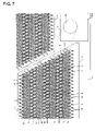
- FIG. 7 is an enlarged view of a region enclosed by a one-dot chain line in FIG. 6 .
- FIG. 8 is a partial section view taken along a line VIII-VIII in FIG. 7 .
- FIG. 9 is a partial exploded perspective view of the head body shown in FIG. 1 .
- FIG. 10A is an enlarged section view of an actuator unit shown in FIG. 9
- FIG. 10B is a plan view showing an individual electrode placed on a surface of the actuator unit in FIG. 10A .
- FIG. 11 is a partial side view of the inkjet head shown in FIG. 1 .
- FIG. 12 is a plan view of a head body according to another embodiment, and corresponds to FIG. 6 .
- FIG. 13 is a partial side view of an inkjet head according to the another embodiment, and corresponds to FIG. 11 .
- FIG. 1 is an external perspective view of an inkjet head 1 , which is used in an inkjet printer.
- FIG. 2 is a section view taken along a line II-II shown in FIG. 1 .
- the inkjet head 1 has a shape elongating in a main scanning direction.
- the inkjet head 1 has a head body 1 a , a reservoir unit 70 , two thin film filters 54 a and four thin film filters 54 b , and a control section 80 for controlling driving of the head body 1 a in order from its bottom.
- a control section 80 for controlling driving of the head body 1 a in order from its bottom.
- the control section 80 has: a main board 82 ; sub-boards 81 , which are placed on the both sides of the main board 82 ; and driver ICs 83 , which are fixed to side faces of the sub-boards 81 opposed to the main board 82 .
- the driver ICs 83 generate a signal for driving actuator units 21 , which are included in the head body 1 a.
- the main board 82 and the sub-boards 81 have a rectangular planes elongating in the main scanning direction, and are upright in parallel to each other.
- the main board 82 is fixed to the upper face of the reservoir unit 70 .
- the sub-boards 81 are above the reservoir unit 70 and are placed on the both sides of the main board 82 with being separated from the main board 82 by the same distance.
- the main board 82 and the sub-boards 81 are electrically connected to each other.
- Heat sinks 84 are fixed to faces of the driver ICs 83 opposed to the sub-boards 81 .
- the heat sinks 84 are formed on the both side faces of the sub-boards 81 , and the driver ICs 83 are thermally coupled to the heat sinks 84 via thermal conduction sheets 85 .
- Each of FPCs (Flexible Printed Circuits) 50 function as a power supplying member.
- One end of each FPC 50 which functions as a fixed portion, horizontally extends along a plane of a flow path unit 4 .
- the fixed portions are fixed and connected to the actuator units 21 .
- Extending portions which are withdrawn from the fixed portions of the FPCs 50 , are bent and extend in a direction (the upward direction in FIG. 2 ) away from the head body 1 a .
- parts of the extending portions are accommodated in recesses 53 (functioning as first recesses), which are formed in side faces of the reservoir unit 70 .
- the other ends of the FPCs 50 are connected to the sub-boards 81 .
- the FPCs 50 are connected also to the driver ICs 83 on the way from the actuator units 21 to the sub-boards 81 . Namely, the FPCs 50 are electrically connected to the sub-boards 81 and the driver ICs 83 to transmit signals output from the sub-boards 81 to the driver ICs 83 , and supply driving signals output from the driver ICs 83 to the actuator units 21 .
- the inkjet head 1 is further provided with an upper cover 51 , which covers the control section 80 , and a lower cover 52 (functioning as a cover member), which covers a lower portion of the head 1 .
- the covers 51 , 52 prevent inks scattering in the printing process from adhering to the control section 80 , etc.
- the upper cover 51 is omitted so that the control section 80 can be seen.
- the upper cover 51 has an arched ceiling, and covers the control section 80 .
- the lower cover 52 has a substantially rectangular cylindrical shape, which is open upward and downward.
- the lower cover 52 covers a lower portion of the main board 82 .
- upper walls 52 b which projects inward from the upper end of the sidewall of the lower cover 52 , is formed.
- the lower end of the upper cover 51 is placed on a portion where the upper wall 52 b is connected to the sidewall.
- the lower cover 52 and the upper cover 51 have a substantially same width as that of the head body 1 a.
- each of the both sidewalls (only one of the sidewalls is shown in FIG. 1 ) of the lower cover 52 , two projections 52 a (functioning as accommodation regions) projecting downward are arranged in the longitudinal direction of the lower cover.
- the projections 52 a are placed in the recesses 53 while covering the extending portions of the FPCs 50 accommodated in the recesses 53 .
- the projections 52 a face the side faces of the reservoir unit 70 with a gap therebetween.
- the lower end faces of the sidewalls other than the projections 52 a abut against the upper face of the reservoir unit 70 (functioning as a first face of the reservoir unit 70 ).
- the tip end faces of the projections 52 a face the flow path unit 4 of the head body 1 a while forming a gap therebetween for absorbing a production error.
- a sealant (not shown) is applied between (i) all of the end face of the lower cover 52 and (ii) the reservoir unit 70 and the flow path unit 4 .
- a sealant made of a soft material is used, and specifically a silicon resin is used for sealing.
- FIG. 3 is a section view of the reservoir unit 70 and the head body 1 a taken along the main scanning direction.
- FIG. 4 is an exploded plan view of the reservoir unit 70 .
- the scale in the vertical direction is expanded, and an ink flow path of the reservoir unit 70 , which is not usually shown in a section taken along the same line, is shown desirably.
- the reservoir unit 70 temporarily stores ink, and supplies the stored ink to the flow path unit 4 of the head body 1 a .
- the reservoir unit 70 has a stacked layer structure in which seven plates 71 , 73 , 74 , 75 , 76 , 77 , and 78 that have a rectangular plane elongating in the main scanning direction (see FIG. 1 ), and one damper sheet 72 are stacked.
- the seven plates 71 , 73 to 78 are plates of a metal such as stainless steel.
- circular holes 71 a , 71 b are formed in the vicinities of one and other ends of the first plate 71 in the longitudinal direction, respectively.
- the circular holes 71 a , 71 b are placed in positions, which are shifted from the center of the first plate 71 in the width direction toward the one and other width ends.
- An oval recess 71 c which elongates in the longitudinal direction of the first plate 71 , is formed in the lower face (the face on the side of the damper sheet 72 ) of the first plate 71 .
- the oval recess 71 c is positioned between the center of the first plate 71 in the longitudinal direction and the circular hole 71 b .
- a circular hole 71 d is formed in the center of the bottom of the oval recess 71 c .
- the oval recess 71 c and the damper sheet 72 which will be described below, constitute a damper chamber.
- the damper sheet 72 which is the second layer from the top, is made of a flexible thin film member. As shown in FIGS. 3 and 4B , circular holes 72 a , 72 b corresponding to the circular holes 71 a , 71 b formed in the first plate 71 are formed in the damper sheet 72 .
- the material of the flexible thin film member may be a metal, a resin, or the like, and is not limited those examples so long as it can easily bend in accordance with pressure variation in the ink.
- used is a composite resin film in which a gas barrier film is added to a PET (polyethylene terephtalate) resin that originally has an excellent gas barrier property. According to this configuration, transmission of air or steam through the flexible thin film member is very suppressed, and the member functions also as an excellent damper against pressure variation in the ink.
- the fourth plate 74 which is the fourth layer from the top, as shown in FIGS. 3 and 4D , thin recesses 74 a , 74 b are formed so as to obliquely elongate toward the center of the fourth plate 74 in the short side direction from regions corresponding to the circular holes 71 a , 71 b formed in the first plate 71 . Furthermore, an oval hole 74 c , which elongates to the center of the fourth plate 74 while communicating with the thin recess 74 a , is formed in the fourth plate 74 . Two step faces 74 d , 74 e , which have different heights, are formed in the peripheral portion of the oval hole 74 c .
- a reservoir filter 74 g which removes dust and the like in the ink, is placed on the step face 74 e , which is lower than the step face 74 d . Furthermore, an oval recess 74 f , which elongates to the center of the fourth plate 74 while communicating with the thin recess 74 b , is formed in the fourth plate 74 .
- the oval recess 74 f which is concaved, has a shape and size, which are substantially identical with those of the oval hole 73 c of the third plate 73 .
- the oval recess 74 f is open on the side of the third plate 73 .
- the bottom faces of the thin recesses 74 a , 74 b ; those of the step face 74 d ; and the oval recess 74 f are formed on the same plane.
- a damper communication port 74 h is formed in a sidewall in the vicinity of the center of the fourth plate 74 .
- the oval hole 74 c and the oval recess 74 f communicate with each other through the damper communication port 74 h .
- the thin recess 74 a , and the portion of the oval hole 74 c on the side of the plate 73 with respect to the step face 74 e form an upstream ink reservoir 61 a .
- the oval recess 74 f and the thin recess 74 b form a damper flow path 62 .
- a circular hole 75 a is formed in the center of the fifth plate 75 , which is the fifth layer from the top.
- the circular hole 75 a forms a drop flow path 63 .
- the fifth plate 75 is stacked from the lower side so that the circular hole 75 a communicates with the through hole 74 c of the fourth plate 74 .
- the circular hole 75 a faces an acute angle portion of the through hole 74 c , which is on the side of the center of the fourth plate 74 .
- a through hole 76 a is formed in the sixth plate 76 , which is the sixth layer from the top.
- the plan shape of the through hole 76 a elongates so as to be bent and tapered along the main scanning direction, and symmetric about its center.
- the through hole 76 a includes a main flow path 76 b , which elongates in the main scanning direction, and tributary flow paths 76 c , which diverge from the main flow path 76 b .
- the tributary flow paths 76 c have a flow path width that is smaller than that of the main flow path 76 b .
- Each two tributary flow paths 76 c which elongate in the same direction, are paired. Two pairs of tributary flow paths 76 c , which elongate in different directions, elongate from each end of the main flow path 76 b in the width direction while separating from each other in the longitudinal direction of the main flow path 76 b .
- the four pairs of tributary flow paths 76 c are arranged in a staggered pattern.
- the portion of the oval hole 74 c of the fourth plate 74 on the side of the plate 75 with respect to the step face 74 e , the circular 75 a of the fifth plate 75 , and the through hole 76 a form a downstream ink reservoir 61 b .
- a total of ten circular holes 77 a are formed in positions corresponding to the both ends of the main flow path 76 b formed in the sixth plate 76 in the longitudinal direction, and tip end portions of the tributary flow paths 76 c .
- Five of the circular holes 77 a are arranged in the longitudinal direction in the vicinity of each end of the seventh plate 77 in the width direction. Specifically, one, two, and two holes 77 a are arranged in the one width end in order from one end side (the left side of FIG.
- FIG. 5 is a partial plan view of the lower face of the eighth plate 78 .
- a region against which the thin film filters 54 a , 54 b abut is indicated by the one-dot chain line.
- surfaces of the downward projecting portions function as second regions 57 at least part of which the thin film filters 54 a , 54 b abut against and are joined to by an adhesive agent.
- Each of the second regions 57 includes a groove region 57 a where lattice-like grooves are formed, and a flat non-groove region 57 b where the lattice-like grooves are not formed.
- the lower-face openings (the ink supply ports 59 ) of the circular holes 78 a are formed in the groove region 57 a .
- the thin film filters 54 a , 54 b are placed so as to abut against the groove region 57 a while covering the ink supply ports 59 .
- the non-groove region 57 b has an annular shape along the outer edges of the thin film filters 54 a , 54 b.
- the reservoir unit 70 of this embodiment is configured so that the seven plates 71 , 73 to 78 and the one damper sheet 72 are stacked and fixed to each other while being positioned.
- the side faces of the reservoir unit 70 connect its upper face (first face) and its lower face (second face).
- the three plates 71 , 73 , 74 are longer in the longitudinal direction than the remaining plates 75 to 78 .
- the inkjet head 1 can be fixed to a fixing portion (not shown) of the printer with using the both end portions of the three plates 71 , 73 , 74 , i.e., the portions which further extend toward the both sides in the longitudinal direction as compared with the plates 75 to 78 .
- each of the plates 71 , 73 to 78 of the width direction As shown in FIGS. 4A to 4H , two and two or a total of four rectangular notches 53 a to 53 g are formed in the longitudinal direction in a staggered pattern.
- the recesses 53 which elongate from the upper face of the reservoir unit 70 to the first region 58 to penetrate the reservoir unit 70 in the stack direction, are formed by the notches 53 a to 53 g (see FIGS. 1 , 2 , and 7 ).
- the width of the reservoir unit 70 except the regions where the recesses 53 are formed is substantially identical with that of the flow path unit 4 .
- a region having a predetermined area is required in the peripheries of the ink supply ports 59 . This region is a factor of determining the width of the flow path unit 4 .
- the FPCs 50 which are withdrawn from the actuator units 21 , and the projection regions 52 a of the lower cover 52 , which cover FPCs 50 , are accommodated in the recesses 53 . Therefore, the width of the inkjet head 1 can be reduced to that of the flow path unit 4 .
- the formation of the recesses 53 enables the inkjet head 1 to be miniaturized.
- a recess formed by the first region 58 is continuous with the recesses 53 (the notches 53 g ).
- the frontages (lengths of the openings in the longitudinal direction) of the recesses 53 are wider than those of openings formed by the first region 58 . Since the openings of the recesses 53 are equal to or larger than the openings of the first region 58 , the extended portions of the FPCs 50 , which are withdrawn from the side of the first region 58 can easily extend upward through the recesses 53 .
- each of the rectangular notches 55 a to 55 c is formed in a region corresponding to a region between the thin film filter 54 a and the thin film filter 54 b , which is closest to the filter 54 a .
- the notches 55 a to 55 c form a recess 55 (functioning as a second recess), which extends from the lower face of the plate 75 to reach the second regions 57 of the plate 78 (see FIGS. 1 and 7 ).
- a supply joint 91 and a discharge joint 92 are fixed to the positions of the upper face of the first plate 71 where the circular holes 71 a , 71 b are formed.
- the joints 91 , 92 are cylindrical members, which have base ends 91 b , 92 b having a slightly larger outer diameter. Openings of cylindrical spaces 91 a , 92 a in the lower faces of the base ends 91 b , 92 b are placed on the upper face of the first plate 71 so as to coincide with the openings of the circular holes 71 a , 71 b of the first plate 71 , respectively.
- the flow (indicated by the solid arrows in FIG. 3 ) of the ink, which is supplied through the supply joint 91 into the reservoir unit 70 , will be described.
- the ink which has flown into the circular holes 71 a through the cylindrical space 91 a of the supply joint 91 , flows into the upstream ink reservoir 61 a through the circular holes 72 a , 73 a .
- the ink, which has flown into the upstream ink reservoir 61 a flows into the damper flow path 62 through the damper communication port 74 h , and passes through the reservoir filter 74 g and flows into the downstream ink reservoir 61 b .
- the flow-in ink is caused by the circular hole 75 a of the fifth plate 75 to drop onto a substantially center of the main flow path 76 b of the sixth plate 76 .
- the ink is directed from the substantially center of the main flow path 76 b to the both ends of the main flow path 76 b in the longitudinal direction, and also to the tip ends of the tributary flow paths 76 c .
- the ink which has reached the both ends of the main flow path 76 b in the longitudinal direction and the tip ends of the tributary flow paths 76 c , flows into ink inflow ports 5 b (see FIG.
- the ink is temporarily stored in the upstream ink reservoir 61 a and the downstream ink reservoir 61 b .
- the ink which flows into the damper flow path 62 , is discharged to the outside from the discharge joint 92 , whereby air bubbles existing in the upstream ink reservoir 61 a and the damper flow path 62 can be easily discharged.
- the space on the upstream side of the reservoir filter 74 g is filled with the ink in a state where there is no residual air bubble.
- the third plate 73 serves as a flow path wall, which defines the damper flow path 62 .
- the opening of the oval hole 73 c which is formed in the flow path wall, is covered by the damper sheet 72 .
- the region of the damper sheet 72 which covers the opening of the oval hole 73 c , faces the oval recess 71 c of the first plate 71 .
- the space, which is defined by the damper sheet 72 and the oval recess 71 c forms a damper chamber.
- the damper chamber communicates with the atmosphere through the circular hole 71 d . Namely, the damper sheet 72 is interposed between the ink in the damper flow path 62 and the atmosphere.
- FIG. 6 is a plan view of the head body 1 a to which the thin film filters 54 a , 54 b are joined.
- the head body 1 a includes the flow path unit 4 and the four actuator units 21 , which are fixed to the upper face of the flow path unit 4 .
- the flow path unit 4 has a substantially rectangular parallelepiped external shape, which has an approximately same width as the reservoir unit 70 , and which has a length in the main scanning direction substantially equal to the length of a stack structure formed by the fifth to eighth plates 75 to 78 of the reservoir unit 70 .
- the flow path unit 4 is formed with a manifold flow path 5 and many individual ink flow paths 32 , which communicate with the manifold flow path 5 , and each of which includes a pressure chamber 10 and a nozzle 8 (see FIG. 8 ).
- the upper face of the flow path unit 4 functions as an inflow-port face 4 a in which ten ink inflow ports 5 b communicating with the manifold flow path 5 are formed.
- the ink inflow ports 5 b are placed so as to correspond to the ink supply ports 59 of the circular holes 78 a formed in the eighth plate 78 . Namely, five ink inflow ports 5 b are arranged in the longitudinal direction in the vicinity of each of the width ends of the flow path unit 4 .
- one, two, and two ink flow ports 5 b are arranged in the one width end in order from one end side (the upper side of FIG. 6 ) in the longitudinal direction, and one, two, and two ink flow ports 5 b are arranged in the other width end in order from the other end side (the lower side of FIG. 6 ) in the longitudinal direction, so as to be separated from each other in a staggered manner.
- the actuator units 21 have a function of selectively applying an ejection energy to the ink in the pressure chambers 10 formed in the flow path unit 4 , and have a trapezoidal plan shape.
- the four actuator units 21 are placed in a staggered pattern so as to avoid the ink inflow ports 5 b .
- the parallel opposing sides extend along the longitudinal direction of the flow path unit 4 . Oblique sides of adjacent actuator units 21 overlap with each other with respect to the width direction of the flow path unit 4 .
- the four actuator units 21 have a relative positional relationship in which the actuator units 21 are separated by the same distance from the center of the flow path unit 4 in the width direction toward the opposite sides.
- the actuator units 21 are placed in a region, which faces the first region 58 of the reservoir unit 70 .
- the FPCs 50 connected to the actuator units 21 are withdrawn from the longer ones of the parallel opposing sides of the actuator unit 21 .
- the thin film filters 54 a , 54 b are thin films having: an ink not-passing region, which does not allow the ink to pass therethrough; and an ink passing region, which allows the ink to pass therethrough while filtering dust and the like in the ink.
- the thin film filters 54 a , 54 b are joined by an adhesive agent to the second regions 57 of the reservoir unit 70 and to the inflow-port face 4 a of the flow path unit. At this time, the ink passing regions of the thin film filters 54 a , 54 b are sandwiched between the ink supply ports 59 opening in the second regions 57 and the corresponding ink inflow ports 5 b opening in the inflow-port face 4 a of the flow path unit 4 .
- the thin film filters 54 a are placed to correspond to the ink inflow ports 5 b respectively formed in the vicinities of the ends of the flow path unit 4 in the longitudinal direction.
- the think film filters 54 a extend in a band-like manner over the whole region in the short side direction of the flow path unit 4 .
- Each of the thin film filters 54 b is placed between the thin film filters 54 a so as to cover two of the ink inflow ports 5 b , which are arranged in a staggered pattern.
- no actuator unit 21 is located between a certain thin film filters 54 a and a thin film filters 54 b closest to the certain thin film filter 54 a .
- An actuator unit 21 is present between a certain thin film filter 54 a and a thin film filter 54 b other than the thin film filter 54 b closest to the certain thin film filter 54 a .
- An actuator unit 21 is present between the thin film filters 54 b.
- FIG. 7 is an enlarged view of the region enclosed by the one-dot chain line in FIG. 6 .
- the nozzles 8 , pressure chambers 10 , and apertures 12 which are placed below the actuator units 21 , and which are to be drawn by broken lines, are drawn by solid lines.
- FIG. 8 is a partial section view taken along a line VIII-VIII shown in FIG. 7 .
- FIG. 9 is a partial exploded perspective view of the head body 1 a .
- FIG. 10A is an enlarged section view of the actuator unit 21 .
- FIG. 10B is a plan view showing an individual electrode 35 placed on the surface of the actuator unit 21 in FIG. 10A .
- ink ejection surface in which the many nozzles 8 are arranged in a matrix are formed on the lower face of the flow path unit 4 .
- the pressure chambers 10 are arranged in a large number in a matrix in a similar manner as the nozzles 8 .
- the ink ejection surface in which the nozzles 8 are open in a matrix, and the surface in which the pressure chambers 10 are arranged in a matrix constitute a pair of opposing surfaces of the flow path unit 4 .
- a plurality of individual ink flow paths 32 are formed in the flow path unit 4 so as to be sandwiched between the pair of faces.
- the actuator units 21 are fixed together with the thin film filters 54 a , 54 b onto the surface in which the pressure chambers 10 are arranged.
- the flow path unit 4 is formed by nine metal plates which are a cavity plate 22 , a base plate 23 , an aperture plate 24 , a supply plate 25 , manifold plates 26 , 27 , 28 , a cover plate 29 , and a nozzle plate 30 in order from its top.
- These plates 22 to 30 have a rectangular plane, which elongate in the main scanning direction (see FIG. 1 ).
- through holes which correspond to the ink inflow ports 5 b (see FIG. 6 ), and those, which correspond to the pressure chambers 10 and have a substantially rhombus shape, are formed in a large number.
- a communication hole between the pressure chamber 10 and the aperture 12 , and that between the pressure chamber 10 and the nozzle 8 are formed, and communication holes between the ink inflow ports 5 b and the manifold flow path 5 are formed.
- a through hole corresponding to the aperture 12 , and a communication hole between the pressure chamber 10 and the nozzle 8 are formed, and communication holes between the ink inflow ports 5 b and the manifold flow path 5 are formed.
- the supply plate 25 for each of the pressure chambers 10 , a communication hole between the aperture 12 and a sub-manifold flow path 5 a , and a communication hole between the pressure chamber 10 and the nozzle 8 are formed, and communication holes between the ink inflow ports 5 b and the manifold flow path 5 are formed.
- a communication hole between the pressure chamber 10 and the nozzle 8 , and through holes which, when the plates are stacked, communicate with each other to be formed as the manifold flow path 5 and the sub-manifold flow path 5 a are formed.
- a communication hole between the pressure chamber 10 and the nozzle 8 is formed in the cover plate 29 .
- a hole corresponding to the nozzle 8 is formed in the nozzle plate 30 .
- the nine plates 22 to 30 are stacked and fixed to each other while being positioned so that the individual ink flow paths 32 such as shown in FIG. 8 are formed in the flow path unit 4 .
- the manifold flow path 5 communicating with the ink inflow ports 5 b , and the sub-manifold flow path 5 a branched from the manifold flow path 5 are formed inside the flow path unit 4 .
- the individual ink flow path 32 such as shown in FIG. 8 , which passes from the manifold flow path 5 through the sub-manifold flow path 5 a and the pressure chamber 10 to reach the nozzle 8 is formed.
- the ink which is supplied from the reservoir unit 70 into the flow path unit 4 through the ink inflow ports 5 b , is branched from the manifold flow path 5 to the sub-manifold flow path 5 a , and reaches the nozzle 8 through the aperture 12 , which functions as an orifice, and the pressure chamber 10 .
- Each of the actuator units 21 is configured by four piezoelectric sheets 41 , 42 , 43 , 44 , which are made of a ferroelectric ceramic material of lead zirconate titanate (PZT), and which have a thickness of about 15 ⁇ m (see FIG. 10A ).
- the thickness of the actuator units 21 in a direction perpendicular to the inflow-port face 4 a of the flow path unit 4 is larger than the thicknesses of the thin film filters 54 a , 54 b (see FIG. 11 ).
- the piezoelectric sheets 41 to 44 are placed over the many pressure chambers 10 , which are formed to correspond to one ink ejection surface.
- Individual electrodes 35 are formed in positions on the uppermost piezoelectric sheet 41 and corresponding to the pressure chambers 10 .
- a common electrode 34 which is over the whole sheet and has a thickness of about 2 ⁇ m, is sandwiched between the uppermost piezoelectric sheet 41 and the piezoelectric sheet 42 , which is below the piezoelectric sheet 41 .
- the individual electrodes 35 and the common electrode 34 are made of a metal material such as Ag—Pd. No electrode is placed between the piezoelectric sheets 42 , 43 , and between the piezoelectric sheets 43 , 44 .
- Each of the individual electrodes 35 has a thickness of about 1 ⁇ m. As shown in FIG. 10B , each of the individual electrodes 35 has a substantially rhombus plan shape, which is similar to the plan shape of the pressure chambers 10 . One of the acute angle portions of the individual electrode 35 having a substantially rhombus shape is elongated. A circular land 36 , which is electrically connected to the individual electrode 35 and has a diameter of about 160 ⁇ m, is disposed at the tip end of the elongated portion. The land 36 is made of gold, which contains, for example, a glass frit. As shown in FIG.
- the land 36 is formed in a position, which is on the elongated portion of the individual electrode 35 and is opposed to the wall of the cavity plate 22 defining the pressure chamber 10 with respect to the thickness direction of the piezoelectric sheets 41 to 44 , i.e., the position, which does not overlap with the pressure chamber 10 .
- the land 36 is electrically joined to a contact disposed on the FPC 50 (see FIG. 2 ).
- the common electrode 34 is grounded in a region, which is not shown. Therefore, the common electrode 34 is equally kept to the ground potential in a region corresponding to all the pressure chambers 10 .
- the individual electrodes 35 (the lands 36 ) are connected to the driver ICs 83 through the FPCs 50 including other lead lines, which are independent for the individual electrodes 35 , in order to enable their potentials to be selectively controlled (see FIG. 2 ).
- the piezoelectric sheet 41 is polarized in the thickness direction.
- one of the individual electrodes 35 is set to a potential different from that of the common electrode 34 and an electric field is applied to the piezoelectric sheet 41 in the polarization direction
- a portion of the piezoelectric sheet 41 to which the electric field is applied operates as an active portion, which is distorted by the piezoelectric effect.
- the piezoelectric sheet 41 is extended or contracted in the thickness direction, and contracted or extended in the planar direction by the piezoelectric transverse effect.
- the remaining three piezoelectric sheets 42 to 44 are inactive layers, which have no region sandwiched between the individual electrodes 35 and the common electrode 34 and thus cannot be spontaneously deformed.
- each of the actuator units 21 is of the so-called unimorph type in which the upper one piezoelectric sheet 41 that is apart from the pressure chamber 10 is formed as a layer including the active layer, and the lower three piezoelectric sheets 42 to 44 that are close to the pressure chambers 10 are formed as the inactive layers.
- the piezoelectric sheets 41 to 44 are fixed to the upper face of the cavity plate 22 defining the pressure chamber 10 .
- the whole piezoelectric sheets 41 to 44 are deformed so as to be convexed toward the pressure chamber 10 (unimorph deformation).
- the volume of the pressure chamber 10 is reduced to increase the pressure in the pressure chamber 10 , the ink is pushed out from the pressure chamber 10 into the nozzle 8 , and the ink is ejected from the nozzle 8 .
- the piezoelectric sheets 41 to 44 are caused to have the original flat shape, and the volume of the pressure chamber 10 is returned to the original value.
- the ink is introduced from the manifold flow path 5 into the pressure chamber 10 , and the ink is again stored in the pressure chamber 10 .
- FIG. 11 is a partial enlarged side view of the inkjet head 1 .
- the lower cover 52 is indicated by a one-dot chain line, and illustration of the FPCs 50 is omitted.
- the reservoir unit 70 and the flow path unit 4 are joined together through the thin film filters 54 a , 54 b , whereby a space S where the actuator units 21 is placed is formed between the first region 58 of the reservoir unit 70 and the inflow-port face 4 a of the flow path unit 4 (see FIG.
- gaps which communicate with the space S, are formed between the thin film filters 54 a and the thin film filters 54 b , and between the thin film filters 54 b .
- gaps between the thin film filters 54 a and the thin film filters 54 b closest to the thin film filters 54 a are sealed by applying a sealant 56 made of a soft material to the recesses 55 .
- the gaps which are open toward the recesses 55 , between the thin film filters 54 a and the thin film filters 54 b , the gaps between the thin film filters 54 b , and a portion between (i) the lower end face of the lower cover 52 and (ii) the reservoir unit 70 and the flow path unit 4 (more specifically, the portion along the one-dot chain line indicating the lower cover 52 in FIG. 11 ) are sealed by the sealant.
- the inkjet head 1 of this embodiment entering of dust or the like into the individual ink flow paths 32 can be suppressed with the simple configuration in which the thin film filters 54 a , 54 b are placed between the flow path unit 4 and the reservoir unit 70 . Since the recess 55 is formed on the side face of the reservoir unit 70 , the sealant 56 for sealing the gaps between the thin film filters 54 a and the thin film filters 54 b closest to the thin film filters 54 a can be easily applied. At this time, the sealant 56 may be applied only to a limited portion, i.e., the recess 55 . Hence, a situation where the sealant 56 flows into or protrudes into another portion does not occur.
- the lower cover 52 Since the gaps between the thin film filters 54 a and the thin film filters 54 b closest to the thin film filters 54 a are sealed by the sealant 56 , the lower cover 52 is not necessary to cover the gaps between the thin film filters 54 a and the thin film filters 54 b closest to the thin film filters 54 a . Therefore, the width of the lower cover 52 is not widened to be larger than that of the flow path unit 4 , and the inkjet head 1 can be miniaturized. Furthermore, an easily breakable part is eliminated from the projections 52 a of the lower cover 52 . Therefore, the production yield can be improved.
- the thickness of the actuator units 21 in the direction perpendicular to the inflow-port face 4 a of the flow path unit 4 is larger than the thicknesses of the thin film filters 54 a , 54 b . Even after the actuator unit 21 and the thin film filters 54 a , 54 b are fixed to the inflow-port face 4 a of the flow path unit 4 , therefore, the individual electrodes 35 and the lands 36 can be easily formed on the actuator unit 21 .
- the configuration in which the thin film filters 54 a , 54 b are placed on the inflow-port face 4 a can prevent dust, dirt, a foreign material, or the like, which may be produced when the individual electrodes 35 and the land 36 are formed on the actuator units 21 , from entering the flow path unit 4 .
- the above embodiment is configured so that the thickness of the actuator units 21 in the direction perpendicular to the inflow-port face 4 a of the flow path unit 4 is larger than the thicknesses of the thin film filters 54 a , 54 b .
- the thickness of the actuator units 21 may be equal to the thicknesses of the thin film filters 54 a , 54 b , or smaller than the thicknesses of the thin film filters 54 a , 54 b.
- the whole circumferences of the outer edges of the thin film filters 54 a , 54 b abut against the non-groove region 57 b in the second regions 57 of the reservoir unit 70 .
- only parts of the outer edges of the thin film filters 54 a , 54 b may abut against the non-groove region 57 b .
- the outer edges of the thin film filters 54 a , 54 b may abut against the non-groove region 57 b in the vicinities of the width ends of the flow path unit 4 .
- the outer edges of the thin film filters 54 a , 54 b may abut against the non-groove region 57 b so as to have an approximately C-like shape, which surrounds the ink inflow ports 5 b or the ink supply ports 59 from portions adjacent to the width ends of the flow path unit 4 .
- the whole circumferences of the outer edges of the thin film filters 54 a , 54 b may not abut against the non-groove region 57 b . According to this configuration, the degree of freedom of the regions where the thin film filters 54 a , 54 b are to be placed is enhanced, and the thin film filters 54 a , 54 b can be easily placed.
- the recesses 55 are formed in the side faces of the reservoir unit 70 , and (i) the gap between each filter 54 a and the filter 54 b closest to each filter 54 a and (ii) the recesses 55 are sealed with the sealant 56 .
- an integrated filter 54 c may be used as shown in FIG. 12 .
- the actuator units 21 are arranged on the inflow-port face 4 a of the flow path unit 4 in a row in the longitudinal direction of the flow path unit 4 .
- the filters 54 b are disposed between the actuator units 21 .
- the filters 54 c are disposed outside the row of the actuator units 21 . Specifically, each filter 54 c extends along two adjacent sides of the actuator unit 21 , which is located at a corresponding end of the row of the actuator units ( 21 ).
- each filter 54 c is a single part in the another embodiment. Therefore, as shown in FIG. 13 , the reservoir unit 70 of this embodiment is not formed with the recess 55 .
- the gaps between the ends of the projections 52 a of the cover member 52 and the inflow-port face 4 a of the flow path unit 4 are sealed with the sealant.
- a combination of the filters 54 b , 54 c and the sealant surrounds the row of the actuator units 21 (i.e., a circumference of a group of the four actuator units 21 ).
- each integrated filter 54 c is the single part, it is not necessary to seal the gap between each filter 54 a and the corresponding filter 54 b closets to the filter 54 a with the sealant. Furthermore, it is not necessary to form the recesses 55 in the side faces of the reservoir unit 70 .
- the reservoir unit 70 which has a simpler configuration (that is, has no recess 55 ), can prevent ink mist from entering the space S. Therefore, it is possible to prevent the actuator units 21 from being damaged by ink mist.
- the inkjet head of the invention is not limited to the piezoelectric type inkjet head having the actuator units 21 , and may be a thermal type inkjet head, or an electrostatic type inkjet head.
- the application of the inkjet head of the invention is not limited to a printer, and the inkjet head may be applied to an inkjet facsimile apparatus or copier.
Landscapes
- Particle Formation And Scattering Control In Inkjet Printers (AREA)
- Ink Jet (AREA)
Priority Applications (1)
| Application Number | Priority Date | Filing Date | Title |
|---|---|---|---|
| US12/414,416 US7712873B2 (en) | 2005-03-24 | 2009-03-30 | Inkjet head |
Applications Claiming Priority (2)
| Application Number | Priority Date | Filing Date | Title |
|---|---|---|---|
| JP2005-085798 | 2005-03-24 | ||
| JP2005085798A JP4475153B2 (ja) | 2005-03-24 | 2005-03-24 | インクジェットヘッド |
Related Child Applications (1)
| Application Number | Title | Priority Date | Filing Date |
|---|---|---|---|
| US12/414,416 Division US7712873B2 (en) | 2005-03-24 | 2009-03-30 | Inkjet head |
Publications (2)
| Publication Number | Publication Date |
|---|---|
| US20060214997A1 US20060214997A1 (en) | 2006-09-28 |
| US7530677B2 true US7530677B2 (en) | 2009-05-12 |
Family
ID=36688160
Family Applications (2)
| Application Number | Title | Priority Date | Filing Date |
|---|---|---|---|
| US11/387,855 Active 2027-07-07 US7530677B2 (en) | 2005-03-24 | 2006-03-24 | Inkjet head |
| US12/414,416 Expired - Lifetime US7712873B2 (en) | 2005-03-24 | 2009-03-30 | Inkjet head |
Family Applications After (1)
| Application Number | Title | Priority Date | Filing Date |
|---|---|---|---|
| US12/414,416 Expired - Lifetime US7712873B2 (en) | 2005-03-24 | 2009-03-30 | Inkjet head |
Country Status (6)
| Country | Link |
|---|---|
| US (2) | US7530677B2 (de) |
| EP (1) | EP1705018B1 (de) |
| JP (1) | JP4475153B2 (de) |
| CN (2) | CN100480048C (de) |
| AT (1) | ATE405428T1 (de) |
| DE (1) | DE602006002294D1 (de) |
Cited By (1)
| Publication number | Priority date | Publication date | Assignee | Title |
|---|---|---|---|---|
| US20130147887A1 (en) * | 2011-12-13 | 2013-06-13 | Yu Kimura | Liquid discharge head and image forming apparatus |
Families Citing this family (5)
| Publication number | Priority date | Publication date | Assignee | Title |
|---|---|---|---|---|
| JP4735694B2 (ja) * | 2008-09-25 | 2011-07-27 | ブラザー工業株式会社 | 液体吐出ヘッド |
| JP6044409B2 (ja) | 2013-03-25 | 2016-12-14 | セイコーエプソン株式会社 | ヘッドユニット、および、液体噴射装置 |
| JP6288439B2 (ja) * | 2014-03-31 | 2018-03-07 | セイコーエプソン株式会社 | 液体噴射ヘッド及び液体噴射装置並びに液体噴射ヘッドの製造方法 |
| JP6503720B2 (ja) * | 2014-12-11 | 2019-04-24 | セイコーエプソン株式会社 | 液体吐出装置および液体吐出モジュール |
| JP6950425B2 (ja) * | 2017-09-29 | 2021-10-13 | ブラザー工業株式会社 | ヘッドユニット及び液体吐出装置 |
Citations (4)
| Publication number | Priority date | Publication date | Assignee | Title |
|---|---|---|---|---|
| US5489930A (en) | 1993-04-30 | 1996-02-06 | Tektronix, Inc. | Ink jet head with internal filter |
| EP1403063A1 (de) | 2002-09-25 | 2004-03-31 | Brother Kogyo Kabushiki Kaisha | Tintenstrahlkopf, Filterbausatz zur Herstellung des Tintenstrahlkopfes, und Tintenstrahlkopfherstellungsvefahren unter Benutzung des Filterbausatzes |
| US20040165028A1 (en) | 2000-08-30 | 2004-08-26 | Brother Kogyo Kabushiki Kaisha | Ink-jet head and method of fabricating same |
| EP1506867A1 (de) | 2003-08-14 | 2005-02-16 | Brother Kogyo Kabushiki Kaisha | Tintenstrahlkopf |
Family Cites Families (1)
| Publication number | Priority date | Publication date | Assignee | Title |
|---|---|---|---|---|
| DE10244924A1 (de) | 2002-09-25 | 2004-04-08 | Sms Demag Ag | Anschlussleitung für ein Kühlelement für einen Schachtofen |
-
2005
- 2005-03-24 JP JP2005085798A patent/JP4475153B2/ja not_active Expired - Fee Related
-
2006
- 2006-03-17 AT AT06005493T patent/ATE405428T1/de not_active IP Right Cessation
- 2006-03-17 EP EP06005493A patent/EP1705018B1/de not_active Ceased
- 2006-03-17 DE DE602006002294T patent/DE602006002294D1/de not_active Expired - Lifetime
- 2006-03-24 CN CNB2006100680566A patent/CN100480048C/zh not_active Expired - Fee Related
- 2006-03-24 CN CN2009100083249A patent/CN101503028B/zh not_active Expired - Fee Related
- 2006-03-24 US US11/387,855 patent/US7530677B2/en active Active
-
2009
- 2009-03-30 US US12/414,416 patent/US7712873B2/en not_active Expired - Lifetime
Patent Citations (6)
| Publication number | Priority date | Publication date | Assignee | Title |
|---|---|---|---|---|
| US5489930A (en) | 1993-04-30 | 1996-02-06 | Tektronix, Inc. | Ink jet head with internal filter |
| US20040165028A1 (en) | 2000-08-30 | 2004-08-26 | Brother Kogyo Kabushiki Kaisha | Ink-jet head and method of fabricating same |
| EP1403063A1 (de) | 2002-09-25 | 2004-03-31 | Brother Kogyo Kabushiki Kaisha | Tintenstrahlkopf, Filterbausatz zur Herstellung des Tintenstrahlkopfes, und Tintenstrahlkopfherstellungsvefahren unter Benutzung des Filterbausatzes |
| EP1506867A1 (de) | 2003-08-14 | 2005-02-16 | Brother Kogyo Kabushiki Kaisha | Tintenstrahlkopf |
| JP2005059438A (ja) | 2003-08-14 | 2005-03-10 | Brother Ind Ltd | インクジェットヘッド |
| US20050083379A1 (en) | 2003-08-14 | 2005-04-21 | Brother Kogyo Kabushiki Kaisha | Ink-jet head |
Non-Patent Citations (1)
| Title |
|---|
| European Patent Office, European Search Report for Related EP Application No. 06005493 dated Sep. 1, 2006. |
Cited By (2)
| Publication number | Priority date | Publication date | Assignee | Title |
|---|---|---|---|---|
| US20130147887A1 (en) * | 2011-12-13 | 2013-06-13 | Yu Kimura | Liquid discharge head and image forming apparatus |
| US9266345B2 (en) * | 2011-12-13 | 2016-02-23 | Ricoh Company, Ltd. | Liquid discharge head and image forming apparatus |
Also Published As
| Publication number | Publication date |
|---|---|
| DE602006002294D1 (de) | 2008-10-02 |
| US7712873B2 (en) | 2010-05-11 |
| EP1705018A2 (de) | 2006-09-27 |
| US20090185008A1 (en) | 2009-07-23 |
| EP1705018A3 (de) | 2006-10-04 |
| US20060214997A1 (en) | 2006-09-28 |
| JP4475153B2 (ja) | 2010-06-09 |
| CN101503028B (zh) | 2012-06-20 |
| EP1705018B1 (de) | 2008-08-20 |
| CN1836910A (zh) | 2006-09-27 |
| CN100480048C (zh) | 2009-04-22 |
| ATE405428T1 (de) | 2008-09-15 |
| JP2006264115A (ja) | 2006-10-05 |
| CN101503028A (zh) | 2009-08-12 |
Similar Documents
| Publication | Publication Date | Title |
|---|---|---|
| EP1547775B1 (de) | Tintenstrahlkopf | |
| US7712873B2 (en) | Inkjet head | |
| US7008049B2 (en) | Inkjet head | |
| JP6848985B2 (ja) | インクジェットヘッド及び画像形成装置 | |
| JP4179099B2 (ja) | インクジェットヘッド | |
| CN100546831C (zh) | 喷墨头 | |
| US20070109373A1 (en) | Liquid-droplet jetting apparatus | |
| US7717547B2 (en) | Inkjet head | |
| JP5040263B2 (ja) | 液滴噴射装置 | |
| EP1506870B1 (de) | Tintenstrahlkopf | |
| JP2007268867A (ja) | インクジェットヘッド | |
| JP4640367B2 (ja) | インクジェットヘッド | |
| US7524037B2 (en) | Inkjet recording apparatus | |
| JP4274084B2 (ja) | インクジェットヘッド | |
| EP1506866B1 (de) | Tintenstrahlkopf | |
| JP4415934B2 (ja) | インクジェットヘッド | |
| JP2020199651A (ja) | 液体吐出ヘッド |
Legal Events
| Date | Code | Title | Description |
|---|---|---|---|
| AS | Assignment |
Owner name: BROTHER KOGYO KABUSHIKI KAISHA, JAPAN Free format text: ASSIGNMENT OF ASSIGNORS INTEREST;ASSIGNOR:CHIKAMOTO, TADANOBU;REEL/FRAME:017419/0099 Effective date: 20060310 |
|
| STCF | Information on status: patent grant |
Free format text: PATENTED CASE |
|
| FPAY | Fee payment |
Year of fee payment: 4 |
|
| FPAY | Fee payment |
Year of fee payment: 8 |
|
| MAFP | Maintenance fee payment |
Free format text: PAYMENT OF MAINTENANCE FEE, 12TH YEAR, LARGE ENTITY (ORIGINAL EVENT CODE: M1553); ENTITY STATUS OF PATENT OWNER: LARGE ENTITY Year of fee payment: 12 |