US7537357B2 - Backlight unit for dynamic image and display employing the same - Google Patents
Backlight unit for dynamic image and display employing the same Download PDFInfo
- Publication number
- US7537357B2 US7537357B2 US11/410,958 US41095806A US7537357B2 US 7537357 B2 US7537357 B2 US 7537357B2 US 41095806 A US41095806 A US 41095806A US 7537357 B2 US7537357 B2 US 7537357B2
- Authority
- US
- United States
- Prior art keywords
- light
- emitting devices
- brightness
- position information
- backlight unit
- Prior art date
- Legal status (The legal status is an assumption and is not a legal conclusion. Google has not performed a legal analysis and makes no representation as to the accuracy of the status listed.)
- Active, expires
Links
Images



Classifications
-
- G—PHYSICS
- G09—EDUCATION; CRYPTOGRAPHY; DISPLAY; ADVERTISING; SEALS
- G09G—ARRANGEMENTS OR CIRCUITS FOR CONTROL OF INDICATING DEVICES USING STATIC MEANS TO PRESENT VARIABLE INFORMATION
- G09G3/00—Control arrangements or circuits, of interest only in connection with visual indicators other than cathode-ray tubes
- G09G3/20—Control arrangements or circuits, of interest only in connection with visual indicators other than cathode-ray tubes for presentation of an assembly of a number of characters, e.g. a page, by composing the assembly by combination of individual elements arranged in a matrix no fixed position being assigned to or needed to be assigned to the individual characters or partial characters
- G09G3/34—Control arrangements or circuits, of interest only in connection with visual indicators other than cathode-ray tubes for presentation of an assembly of a number of characters, e.g. a page, by composing the assembly by combination of individual elements arranged in a matrix no fixed position being assigned to or needed to be assigned to the individual characters or partial characters by control of light from an independent source
- G09G3/3406—Control of illumination source
- G09G3/342—Control of illumination source using several illumination sources separately controlled corresponding to different display panel areas, e.g. along one dimension such as lines
- G09G3/3426—Control of illumination source using several illumination sources separately controlled corresponding to different display panel areas, e.g. along one dimension such as lines the different display panel areas being distributed in two dimensions, e.g. matrix
-
- G—PHYSICS
- G02—OPTICS
- G02F—OPTICAL DEVICES OR ARRANGEMENTS FOR THE CONTROL OF LIGHT BY MODIFICATION OF THE OPTICAL PROPERTIES OF THE MEDIA OF THE ELEMENTS INVOLVED THEREIN; NON-LINEAR OPTICS; FREQUENCY-CHANGING OF LIGHT; OPTICAL LOGIC ELEMENTS; OPTICAL ANALOGUE/DIGITAL CONVERTERS
- G02F1/00—Devices or arrangements for the control of the intensity, colour, phase, polarisation or direction of light arriving from an independent light source, e.g. switching, gating or modulating; Non-linear optics
- G02F1/01—Devices or arrangements for the control of the intensity, colour, phase, polarisation or direction of light arriving from an independent light source, e.g. switching, gating or modulating; Non-linear optics for the control of the intensity, phase, polarisation or colour
- G02F1/13—Devices or arrangements for the control of the intensity, colour, phase, polarisation or direction of light arriving from an independent light source, e.g. switching, gating or modulating; Non-linear optics for the control of the intensity, phase, polarisation or colour based on liquid crystals, e.g. single liquid crystal display cells
- G02F1/133—Constructional arrangements; Operation of liquid crystal cells; Circuit arrangements
- G02F1/1333—Constructional arrangements; Manufacturing methods
- G02F1/1335—Structural association of cells with optical devices, e.g. polarisers or reflectors
-
- G—PHYSICS
- G02—OPTICS
- G02B—OPTICAL ELEMENTS, SYSTEMS OR APPARATUS
- G02B5/00—Optical elements other than lenses
-
- G—PHYSICS
- G02—OPTICS
- G02B—OPTICAL ELEMENTS, SYSTEMS OR APPARATUS
- G02B6/00—Light guides; Structural details of arrangements comprising light guides and other optical elements, e.g. couplings
-
- G—PHYSICS
- G09—EDUCATION; CRYPTOGRAPHY; DISPLAY; ADVERTISING; SEALS
- G09G—ARRANGEMENTS OR CIRCUITS FOR CONTROL OF INDICATING DEVICES USING STATIC MEANS TO PRESENT VARIABLE INFORMATION
- G09G2320/00—Control of display operating conditions
- G09G2320/06—Adjustment of display parameters
- G09G2320/0626—Adjustment of display parameters for control of overall brightness
- G09G2320/0633—Adjustment of display parameters for control of overall brightness by amplitude modulation of the brightness of the illumination source
-
- G—PHYSICS
- G09—EDUCATION; CRYPTOGRAPHY; DISPLAY; ADVERTISING; SEALS
- G09G—ARRANGEMENTS OR CIRCUITS FOR CONTROL OF INDICATING DEVICES USING STATIC MEANS TO PRESENT VARIABLE INFORMATION
- G09G2360/00—Aspects of the architecture of display systems
- G09G2360/16—Calculation or use of calculated indices related to luminance levels in display data
Definitions
- the present invention relates to a backlight unit and a display employing a backlight unit, and more particularly, to a backlight unit that provides a dynamic image by properly controlling the brightness of light emitting devices that can be driven independently with respect to an image having a large difference of brightness, and a display employing the backlight unit.
- LCDs Liquid crystal displays
- LCD-TVs mobile communication terminals
- mobile communication terminals and so on. Since an LCD is a light receiving element type display that cannot emit light by itself, the LCD needs a backlight unit in addition to a liquid crystal panel.
- the backlight unit is located in the rear of the liquid crystal panel and emits light onto the liquid crystal panel.
- the backlight unit can be classified as a direct light type backlight unit and an edge light type backlight unit in accordance with the arrangement of a light source.
- the direct light type backlight unit irradiates light from a plurality of light sources provided under the liquid crystal panel toward the liquid crystal panel.
- the edge light type backlight unit emits light from a light source located at a sidewall of a light guide panel (LGP) to the liquid crystal panel.
- a cold cathode fluorescent lamp (CCFL) is generally used as the light source for the edge light type backlight unit.
- LED light emitting diode
- LEDs emitting Lambertian light are used as a point light source for the direct light type backlight unit.
- a conventional backlight unit includes an LED 500 , a diffusion plate 503 and a diffusion sheet 505 for projecting light emitted from the LED 500 onto a liquid crystal panel 510 to be uniform, and a reflection plate 502 for reflecting light that is emitted from the LED 500 to proceed toward the liquid crystal panel 510 located above LED 500 . Further, a prism sheet 507 is provided to correct a light travelling route between the diffusion sheet 505 and the liquid crystal panel 510 and cause the emitted light to proceed toward the liquid crystal panel 510 .
- CCFLs arranged in a line are required for a 26-inch display, and sixteen CCFLs for a 32-inch display.
- the CCFLs as a line light source need to control each current applied thereto.
- all CCFLs are connected in series and it is impossible to finely control a region needing the increase or decrease of the brightness, even though the CCFLs are driven independently. Consequently, the CCFLs cannot provide a dynamic image.
- the conventional backlight unit cannot provide an image needing a partial increase or decrease of brightness, it is difficult to provide a dynamic image.
- the present invention provides a backlight unit capable of providing a dynamic image by controlling the brightness of light-emitting devices separately according to image signals.
- a backlight unit for a light source of a display including: a plurality of light-emitting devices which are disposed on a substrate and driven separately; an image analyzer which analyzes an image signal and extracts position information corresponding to a region of an image requiring a relative increase or decrease of brightness; and a control unit which independently drives and controls light-emitting devices, among the plurality of light-emitting devices, which are located in the region corresponding to the position information which is extracted by the image analyzer.
- the control unit may control the brightness of the plurality of light-emitting devices by adjusting a voltage and/or a current applied to the light-emitting devices.
- the control unit may control the brightness of the plurality of light emitting devices by supplying a higher or lower voltage or current to the light-emitting devices, among the plurality of light-emitting devices, which are located in the region corresponding to the position information which is extracted by the image analyzer relative to voltage or current which is supplied to light-emitting devices which are not located in the region corresponding to the position information.
- the light-emitting devices may include light-emitting diode (LED) chips emitting light having at least two wavelength ranges, and the LED chips are packaged on a base.
- LED light-emitting diode
- the LED chips may be disposed at a periphery of the base.
- a display including: a plurality of light-emitting devices disposed on a substrate and driven separately; an image analyzer which analyzes an image signal and extracts position information which corresponds to a region of an image which requires a relative increase or decrease of brightness; a control unit which independently drives and controls light-emitting devices, among the plurality of light-emitting devices, which are located in the region which corresponds to the position information which is extracted by the image analyzer; and a display panel which displays an image using light emitted from the plurality of light-emitting devices.
- FIG. 1 is a sectional view of a conventional direct light type backlight unit
- FIG. 2 is a sectional view of a display according to an exemplary embodiment of the present invention.
- FIG. 3 is a view illustrating the arrangement of multi-chip light emitting devices used in a display and a backlight unit according to an exemplary embodiment of the present invention
- FIG. 4A is a perspective view of the light-emitting device used in the display and the backlight unit according to an exemplary embodiment of the present invention
- FIG. 4B is a sectional view of the light-emitting device shown in FIG. 4A ;
- FIG. 5 is a view illustrating the arrangement of single-chip light-emitting devices used in a display and a backlight unit according to an exemplary embodiment of the present invention
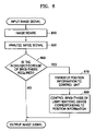
- FIG. 6 is a flowchart illustrating the process of forming an image in the display according to an exemplary embodiment of the present invention.
- FIG. 7 is a block diagram of the display according to an exemplary embodiment of the present invention.
- FIG. 2 is a sectional view of a display according to an exemplary embodiment of the present invention.
- a display 100 includes a display panel 70 for displaying an image and a backlight unit 1 for providing light to the display panel 70 .
- a liquid crystal display can be used as the display panel 70 .
- the LCD includes thin film transistors and electrodes in each pixel and displays an image.
- An electric field is applied to liquid crystals in units of pixels according to an image signal inputted from an image signal processor (not shown), and light emitted from the backlight unit 1 is space-modulated. Through these procedures, an image is displayed.
- the backlight unit 1 includes a plurality of light-emitting devices 15 arranged two-dimensionally on a PCB substrate 20 and a control unit 18 controlling the light-emitting devices 15 .
- the light-emitting devices 15 are driven electrically and separately and the control unit 18 controls the driving of the light-emitting devices 15 .
- a diffusion plate 40 and a prism sheet 50 are located between the light-emitting devices 15 and the display panel 70 .
- the diffusion plate 40 uniformly projects the light emitted from the light-emitting devices 15 onto the display panel 70 .
- the prism sheet 50 corrects a light travelling path and guides the light toward the liquid crystal panel 70 .
- a polarization enhancement film 60 may be further provided between the prism sheet 50 and the display panel 70 .
- the polarization enhancement film 60 enhances a polarization property to improve an optical efficiency.
- the light-emitting devices 15 are arranged two-dimensionally on the PCB substrate 20 .
- a larger number of light-emitting devices 15 provide a higher resolution.
- the light-emitting devices 15 are formed on the PCB substrate 20 such that current is separately supplied to the PCB substrate 20 .
- the control unit 18 controls current or a voltage for the light-emitting devices 15 .
- the brightness of the light-emitting devices included in a region A of FIG. 3 can be increased or decreased more than that of the other light-emitting devices by supplying relatively higher or lower current or voltage to the light-emitting devices of the region A than to the other light-emitting devices.
- the light-emitting devices 15 may be a multi chip light-emitting device where a plurality of LED chips 5 emitting light with at least two wavelength ranges are configured in one package. Also, the light-emitting device 15 includes a cap 10 for total reflection of the light emitted from the LED chips 5 . The light-emitting devices 15 generate a white light by totally reflecting the light with different wavelengths several times in the LED chips 5 and mixing the light.
- the LED chips 5 are arranged on a base 7 , and the cap 10 is located above the LED chips 5 .
- the LED chips 5 emit light with at least two different wavelength ranges.
- the LED chips 5 may include a first LED chip 5 a emitting light with a red wavelength range, a second LED chip 5 b emitting light with a green wavelength range, and a third LED chip 5 c emitting light with a blue wavelength range.
- the light-emitting device 15 includes eight LED chips: three first LED chips 5 a , two second LED chips 5 b , and three third LED chips 5 c .
- the number or arrangement of LED chips 5 in each wavelength range can be properly determined according to desired color temperature ranges in consideration of an amount of light emitted from LED chips 5 in each wavelength.
- the size of the multi-chip structure does not vary remarkably in comparison with a single-chip structure, so that the size of the light-emitting devices 15 does not increase.
- a space for mixture becomes smaller. Consequently, a thickness of the backlight unit can be reduced.
- the cap 10 is formed of transparent materials, for example, a lens.
- the cap 10 is formed of materials having a larger refractive index than a medium between the light-emitting device 15 and the diffusion plate 40 so as to satisfy the condition for a total reflection.
- the cap 10 can be formed of epoxy resin or poly-methyl methacrylate (PMMA), which has a refractive index of 1.49. Since the cap 10 has a larger refractive index than air, the cap 10 totally reflects several times the light that is projected at a larger angle than a critical angle on its boundary. Light from the light-emitting devices 15 is mixed in the cap 10 and emitted as a white light.
- the different wavelengths of light are mixed in the cap 10 and emitted from the light-emitting diode units toward the diffusion plate 40 , there is no need to mix light between the light-emitting devices 15 and the diffusion plate 40 . Therefore, a distance between the light-emitting devices 15 and the diffusion plate 40 can be shortened.
- the cap 10 may be formed in a cone shape, a dome shape or a poly-pyramid shape. In FIGS. 4A and 4B , the cap 10 is formed in a cone shape.
- the LED chips 5 a , 5 b and 5 c may be disposed not at the center but at the periphery of the base 7 , the generation of a bright light spot can be prevented.
- the bright light spot is a phenomenon in which a relatively bright spot is produced because the light from the light-emitting device 15 is irregularly diffused and then is projected with a relatively high brightness. This bright light spot is one of factors which results in a low picture quality.
- the LED chip 5 is located at the center of the base 7 opposite to the center of the cap 10 , most of the light emitted from the light-emitting device is incident at a smaller angle than the critical angle of the cap 10 . Thus, the light goes straight through the cap 10 or is refracted.
- the LED chip 5 is located at the periphery of the base 7 , most of the light emitted from the LED chip 5 is incident at a larger angle than the critical angle of the cap 10 and is totally reflected inside.
- the light-emitting device 15 can be formed within a single chip and the light-emitting devices emitting light with different wavelengths can be arranged in turn. As shown in FIG. 5 , a first light-emitting device 35 a emitting light with a first wavelength, a second light-emitting device 35 b emitting light with a second wavelength, and a third light-emitting device 35 c emitting light with a third wavelength are alternately arranged on a PCB substrate 30 . Meanwhile, in some cases, when it is necessary to provide light with wavelength needing a greater light intensity than that of other light, two chips emitting light needing the greater light intensity can be arranged consecutively. For example, an amount of a green light can be supplemented by arranging a red light-emitting device, a green light-emitting device, a green light-emitting device, and a blue light-emitting device in sequence.
- the single-chip light-emitting devices 35 a , 35 b and 35 c are driven electrically and separately through a control unit 37 on the PCB substrate 30 .
- the brightness of the light-emitting devices included in a region B of FIG. 5 can be increased or decreased more than that of the other light-emitting devices by supplying a relatively higher or lower current or voltage to the light-emitting devices of the region B than to the other light-emitting devices. Accordingly, a more dynamic image can be provided.
- FIG. 6 is a flowchart illustrating a process of forming an image in the display according to an exemplary embodiment of the present invention.
- FIG. 7 is a block diagram of the display according to an exemplary embodiment of the present invention.
- an image signal unit 710 inputs an image signal to an image board 720 .
- the image board 720 analyzes the image signal and determines whether the image requires an increase or decrease to the brightness.
- a reference value that is used for determining the increase and decrease of the brightness is stored in the image board 720 , and information of a region that requires an increase or decrease to the brightness is extracted from the reference value.
- the control unit 730 adjusts the brightness of the light-emitting devices by controlling a driving current and/or voltage of each of light-emitting devices 740 in the region that corresponds to the position information.
- a display panel 750 performs a space modulation on the light emitted from the light-emitting devices 740 according to the image signal that is input from the image signal unit 710 and then outputs the resulting image.
- a realistic image is provided by controlling a brightness of light-emitting devices that correspond to the region that requires an increase or decrease of brightness.
- the light-emitting devices can be independently driven and controlled. Therefore, the images that are subject to partial increase or decrease of the brightness can be displayed more dynamically and realistically by controlling the current applied to the light-emitting devices.
Landscapes
- Physics & Mathematics (AREA)
- General Physics & Mathematics (AREA)
- Engineering & Computer Science (AREA)
- Optics & Photonics (AREA)
- Computer Hardware Design (AREA)
- Theoretical Computer Science (AREA)
- Nonlinear Science (AREA)
- Liquid Crystal (AREA)
- Chemical & Material Sciences (AREA)
- Crystallography & Structural Chemistry (AREA)
- Mathematical Physics (AREA)
- Planar Illumination Modules (AREA)
- Control Of Indicators Other Than Cathode Ray Tubes (AREA)
- Liquid Crystal Display Device Control (AREA)
- Spectroscopy & Molecular Physics (AREA)
- General Engineering & Computer Science (AREA)
- Led Device Packages (AREA)
Priority Applications (1)
| Application Number | Priority Date | Filing Date | Title |
|---|---|---|---|
| US12/430,577 US8807776B2 (en) | 2005-04-26 | 2009-04-27 | Backlight unit for dynamic image and display employing the same |
Applications Claiming Priority (2)
| Application Number | Priority Date | Filing Date | Title |
|---|---|---|---|
| KR10-2005-0034566 | 2005-04-26 | ||
| KR1020050034566A KR101113236B1 (ko) | 2005-04-26 | 2005-04-26 | 다이나믹한 영상을 위한 백라이트 유닛 및 이를 채용한디스플레이 장치 |
Related Child Applications (1)
| Application Number | Title | Priority Date | Filing Date |
|---|---|---|---|
| US12/430,577 Continuation US8807776B2 (en) | 2005-04-26 | 2009-04-27 | Backlight unit for dynamic image and display employing the same |
Publications (2)
| Publication Number | Publication Date |
|---|---|
| US20060239033A1 US20060239033A1 (en) | 2006-10-26 |
| US7537357B2 true US7537357B2 (en) | 2009-05-26 |
Family
ID=36978008
Family Applications (2)
| Application Number | Title | Priority Date | Filing Date |
|---|---|---|---|
| US11/410,958 Active 2026-11-22 US7537357B2 (en) | 2005-04-26 | 2006-04-26 | Backlight unit for dynamic image and display employing the same |
| US12/430,577 Expired - Lifetime US8807776B2 (en) | 2005-04-26 | 2009-04-27 | Backlight unit for dynamic image and display employing the same |
Family Applications After (1)
| Application Number | Title | Priority Date | Filing Date |
|---|---|---|---|
| US12/430,577 Expired - Lifetime US8807776B2 (en) | 2005-04-26 | 2009-04-27 | Backlight unit for dynamic image and display employing the same |
Country Status (4)
| Country | Link |
|---|---|
| US (2) | US7537357B2 (ko) |
| EP (2) | EP2178076A1 (ko) |
| KR (1) | KR101113236B1 (ko) |
| CN (2) | CN101661711B (ko) |
Cited By (1)
| Publication number | Priority date | Publication date | Assignee | Title |
|---|---|---|---|---|
| US8952882B2 (en) | 2011-05-10 | 2015-02-10 | Au Optronics Corp. | Method for adjusting a backlight of a display device and device thereof |
Families Citing this family (50)
| Publication number | Priority date | Publication date | Assignee | Title |
|---|---|---|---|---|
| KR101176531B1 (ko) * | 2005-05-31 | 2012-08-24 | 삼성전자주식회사 | 백라이트 시스템 및 이를 채용한 액정표시장치 |
| US20070258241A1 (en) * | 2006-05-02 | 2007-11-08 | 3M Innovative Properties Company | Led package with non-bonded converging optical element |
| US7525126B2 (en) * | 2006-05-02 | 2009-04-28 | 3M Innovative Properties Company | LED package with converging optical element |
| US7390117B2 (en) * | 2006-05-02 | 2008-06-24 | 3M Innovative Properties Company | LED package with compound converging optical element |
| US20070257270A1 (en) * | 2006-05-02 | 2007-11-08 | 3M Innovative Properties Company | Led package with wedge-shaped optical element |
| US20070257271A1 (en) * | 2006-05-02 | 2007-11-08 | 3M Innovative Properties Company | Led package with encapsulated converging optical element |
| WO2008011377A2 (en) * | 2006-07-17 | 2008-01-24 | 3M Innovative Properties Company | Led package with converging extractor |
| US8018424B2 (en) * | 2006-10-19 | 2011-09-13 | Au Optronics Corporation | Backlight device with zone control |
| KR101396658B1 (ko) | 2006-12-29 | 2014-05-19 | 엘지디스플레이 주식회사 | 광원 큐브 및 이를 이용한 평면 광원 장치 및 액정 표시장치 |
| WO2008083188A2 (en) * | 2006-12-29 | 2008-07-10 | 3M Innovative Properties Company | Led light source with converging extractor in an optical element |
| US20080186272A1 (en) * | 2007-02-02 | 2008-08-07 | Hong Kong Applied Science And Technology Research Institute Co., Ltd. | Backlit Display and Backlight System Thereof |
| DE102007043903A1 (de) * | 2007-09-14 | 2009-03-26 | Osram Gesellschaft mit beschränkter Haftung | Leucht-Vorrichtung |
| CN101393722B (zh) * | 2007-09-19 | 2012-11-21 | 奇美电子股份有限公司 | 背光模块的控制方法 |
| DK2240924T3 (en) * | 2008-01-09 | 2016-07-04 | Dolby Laboratories Licensing Corp | REDUCING LCD flicker |
| US8493313B2 (en) * | 2008-02-13 | 2013-07-23 | Dolby Laboratories Licensing Corporation | Temporal filtering of video signals |
| JP5430950B2 (ja) * | 2008-04-01 | 2014-03-05 | ミツミ電機株式会社 | 画像表示装置 |
| US8220981B2 (en) * | 2008-05-27 | 2012-07-17 | Lg Electronics Inc. | Liquid crystal display having a plurality of modules |
| WO2009145548A2 (en) * | 2008-05-27 | 2009-12-03 | Lg Electronics Inc. | Led back-light unit and liquid crystal display device using the same |
| ES2748040T3 (es) | 2008-09-30 | 2020-03-12 | Dolby Laboratories Licensing Corp | Gestión de energía mejorada para retroiluminaciones moduladas |
| DK2364458T3 (en) | 2008-11-14 | 2016-07-18 | Dolby Laboratories Licensing Corp | Custom psf'er operating light in clusters |
| JP2010157455A (ja) * | 2008-12-29 | 2010-07-15 | Funai Electric Co Ltd | 液晶表示装置のバックライト |
| KR101089378B1 (ko) * | 2009-06-09 | 2011-12-05 | (주)한국킹유전자 | 디스플레이 장치 및 그 제어방법 |
| KR101660721B1 (ko) * | 2009-06-15 | 2016-09-29 | 엘지전자 주식회사 | 발광 다이오드 패키지 및 이를 포함하는 백라이트 유닛과 디스플레이장치 |
| KR101628366B1 (ko) * | 2009-07-06 | 2016-06-08 | 엘지전자 주식회사 | 광학 어셈블리, 이를 구비한 백라이트 유닛 및 디스플레이 장치 |
| KR20110014869A (ko) * | 2009-08-06 | 2011-02-14 | 엘지전자 주식회사 | 백라이트 유닛 및 그를 이용한 디스플레이 장치 |
| KR20110013101A (ko) * | 2009-08-02 | 2011-02-09 | 엘지전자 주식회사 | 백라이트 유닛 및 그를 이용한 디스플레이 장치 |
| KR20110017581A (ko) * | 2009-08-14 | 2011-02-22 | 엘지전자 주식회사 | 광학 어셈블리, 이를 구비한 백라이트 유닛 및 디스플레이 장치 |
| KR101611616B1 (ko) * | 2009-08-28 | 2016-04-11 | 엘지전자 주식회사 | 백라이트 유닛 및 그를 이용한 디스플레이 장치 |
| WO2011025724A1 (en) | 2009-08-27 | 2011-03-03 | Dolby Laboratories Licensing Corporation | Optical mixing and shaping system for display backlights and displays incorporating the same |
| KR20110023059A (ko) * | 2009-08-28 | 2011-03-08 | 엘지전자 주식회사 | 백라이트 유닛 및 그를 이용한 디스플레이 장치 |
| EP2354817A1 (en) * | 2009-12-14 | 2011-08-10 | Lg Electronics Inc. | Backlight unit, and display apparatus including the backlight unit |
| US20110216555A1 (en) * | 2010-03-05 | 2011-09-08 | High Power Lighting Corp. | Led device for backlight module |
| US8902261B2 (en) * | 2010-03-22 | 2014-12-02 | Himax Display, Inc. | Light source control method of projector |
| TWI511114B (zh) * | 2010-03-24 | 2015-12-01 | Himax Display Inc | 投影機的光源控制方法 |
| US8841145B2 (en) * | 2010-12-08 | 2014-09-23 | Bridgelux, Inc. | System for wafer-level phosphor deposition |
| US8482020B2 (en) | 2010-12-08 | 2013-07-09 | Bridgelux, Inc. | System for wafer-level phosphor deposition |
| US9564078B2 (en) * | 2010-12-17 | 2017-02-07 | Dolby Laboratories Licensing Corporation | Quantum dots for display panels |
| CN102957921A (zh) * | 2011-08-22 | 2013-03-06 | 北京三星通信技术研究有限公司 | 显示装置及其驱动方法 |
| KR20130046042A (ko) * | 2011-10-27 | 2013-05-07 | 삼성전자주식회사 | 백라이트유닛 및 이를 가지는 디스플레이장치 |
| TWI460714B (zh) * | 2011-12-27 | 2014-11-11 | Himax Media Solutions Inc | 可調適控制發光二極體背光源的系統及方法 |
| CN103454824B (zh) * | 2012-05-28 | 2018-04-27 | 联想(北京)有限公司 | 显示装置 |
| EP2933550B1 (en) | 2012-12-17 | 2020-09-02 | LG Innotek Co., Ltd. | Rear-side area warning module |
| KR102092881B1 (ko) * | 2012-12-18 | 2020-03-24 | 엘지이노텍 주식회사 | 조명 장치 |
| TWI533060B (zh) * | 2013-05-30 | 2016-05-11 | 群創光電股份有限公司 | 顯示裝置 |
| CN111243533B (zh) | 2014-03-26 | 2022-11-25 | 杜比实验室特许公司 | 各种显示器中的全局光补偿 |
| CN108873477B (zh) | 2014-08-21 | 2021-08-17 | 杜比实验室特许公司 | 用于驱动局部调光显示器的方法、设备和存储介质 |
| US20170061894A1 (en) * | 2015-08-26 | 2017-03-02 | Canon Kabushiki Kaisha | Image display apparatus |
| US10935838B2 (en) * | 2017-04-19 | 2021-03-02 | Boe Technology Group Co., Ltd. | Backlight module for display apparatus, display apparatus, and method of driving edge-lit backlight module |
| US20220199046A1 (en) * | 2019-09-06 | 2022-06-23 | Hewlett-Packard Development Company, L.P. | Display backlight adjustment based on viewer position |
| CN115547267B (zh) * | 2021-06-30 | 2026-03-06 | 海信视像科技股份有限公司 | 显示设备及背光模组驱动方法 |
Citations (32)
| Publication number | Priority date | Publication date | Assignee | Title |
|---|---|---|---|---|
| JPS6184880A (ja) | 1984-10-02 | 1986-04-30 | Sharp Corp | 固体発光表示装置 |
| US5822053A (en) | 1995-04-25 | 1998-10-13 | Thrailkill; William | Machine vision light source with improved optical efficiency |
| KR19980076384A (ko) | 1997-04-09 | 1998-11-16 | 구자홍 | 액정표시장치의 백라이트 |
| JP2000068562A (ja) | 1998-08-21 | 2000-03-03 | Stanley Electric Co Ltd | Ledランプ |
| JP2000353405A (ja) | 1999-06-08 | 2000-12-19 | Shinichi Kobayashi | 赤、青、緑色発光ダイオード(led)チップで構成するランプ |
| EP1162400A2 (en) | 2000-06-09 | 2001-12-12 | Omnilux s.r.l. | Modular lighting elements with leds (light-emitting diodes) |
| KR20020019579A (ko) | 1999-07-26 | 2002-03-12 | 다마오키 요시카쓰 | 벌크형 렌즈, 발광체, 조명 기구 및 광 정보 시스템 |
| KR20020041480A (ko) | 2000-11-28 | 2002-06-03 | 유순재 | 엘씨디의 백 라이트 광원 모듈 |
| US20020071288A1 (en) | 2000-12-13 | 2002-06-13 | Lim Moo Jong | Backlight unit in liquid crystal display |
| US6443597B1 (en) | 1999-09-01 | 2002-09-03 | Sony Corporation | Plane display unit and plane display device |
| US20020135298A1 (en) | 2001-03-26 | 2002-09-26 | Pelka David G. | Light extractor apparatus |
| JP2003016808A (ja) | 2001-06-29 | 2003-01-17 | Matsushita Electric Ind Co Ltd | 照明装置 |
| US20030052594A1 (en) | 2001-09-18 | 2003-03-20 | Nobuyuki Matsui | Lighting apparatus whose light emitting elements are hard to be taken off |
| KR20030051898A (ko) | 2000-12-06 | 2003-06-25 | 에프코스 아게 | 전기 이중층 커패시터 |
| JP2004029141A (ja) | 2002-06-21 | 2004-01-29 | Mitsubishi Electric Corp | ディスプレイ装置用背面光源、液晶ディスプレイ装置及び背面光源の調整方法 |
| US20040032388A1 (en) | 2002-08-16 | 2004-02-19 | Toppoly Optoelectronics Corp. | Backlight device of a LCD display |
| US20040062040A1 (en) | 2002-09-27 | 2004-04-01 | Heinrich-Jochen Blume | Device for producing an image |
| DE10242292A1 (de) | 2002-09-12 | 2004-04-01 | Sebastian Matthias | Flächenlampe |
| WO2004049292A1 (en) | 2002-11-27 | 2004-06-10 | Koninklijke Philips Electronics N.V. | Active matrix display |
| EP1433877A1 (en) | 2002-12-24 | 2004-06-30 | Nippon Paint Co., Ltd. | Pretreatment method for coating |
| JP2004233809A (ja) | 2003-01-31 | 2004-08-19 | Seiko Epson Corp | 面光源ユニット、それを用いた電気光学装置並びに電子機器 |
| JP2004246117A (ja) | 2003-02-14 | 2004-09-02 | Matsushita Electric Ind Co Ltd | バックライト装置 |
| EP1455002A1 (en) | 2002-12-24 | 2004-09-08 | Nippon Paint Co., Ltd. | Pretreatment method for coating |
| US20040201987A1 (en) * | 2003-04-09 | 2004-10-14 | Citizen Electronics Co., Ltd. | LED lamp |
| KR20040090083A (ko) | 2003-04-16 | 2004-10-22 | 엘지.필립스 엘시디 주식회사 | 액정표시모듈과 그의 구동장치 및 방법 |
| KR20040096186A (ko) | 2003-05-07 | 2004-11-16 | 엘지.필립스 엘시디 주식회사 | 백 라이트 유닛 및 이를 사용한 액정표시장치 |
| US20040228127A1 (en) | 2003-05-16 | 2004-11-18 | Squicciarini John B. | LED clusters and related methods |
| US20040257329A1 (en) | 2003-06-20 | 2004-12-23 | Lg. Philips Lcd Co., Ltd. | Method and apparatus for driving liquid crystal display device |
| US6857767B2 (en) | 2001-09-18 | 2005-02-22 | Matsushita Electric Industrial Co., Ltd. | Lighting apparatus with enhanced capability of heat dissipation |
| US20050248554A1 (en) | 2004-05-04 | 2005-11-10 | Sharp Laboratories Of America, Inc. | Liquid crystal display with filtered black point |
| US20050248524A1 (en) * | 2004-05-04 | 2005-11-10 | Sharp Laboratories Of America, Inc. | Liquid crystal display with colored backlight |
| US7140751B2 (en) | 2004-03-24 | 2006-11-28 | Yuan Lin | Full-color flexible light source device |
Family Cites Families (26)
| Publication number | Priority date | Publication date | Assignee | Title |
|---|---|---|---|---|
| JPS48102585A (ko) * | 1972-04-04 | 1973-12-22 | ||
| US6147728A (en) | 1995-07-17 | 2000-11-14 | Seiko Epson Corporation | Reflective color LCD with color filters having particular transmissivity |
| US6177761B1 (en) * | 1996-07-17 | 2001-01-23 | Teledyne Lighting And Display Products, Inc. | LED with light extractor |
| JPH10319871A (ja) * | 1997-05-19 | 1998-12-04 | Kouha:Kk | Ledディスプレイ装置 |
| US6200002B1 (en) * | 1999-03-26 | 2001-03-13 | Philips Electronics North America Corp. | Luminaire having a reflector for mixing light from a multi-color array of leds |
| JP3523170B2 (ja) * | 2000-09-21 | 2004-04-26 | 株式会社東芝 | 表示装置 |
| US6547416B2 (en) * | 2000-12-21 | 2003-04-15 | Koninklijke Philips Electronics N.V. | Faceted multi-chip package to provide a beam of uniform white light from multiple monochrome LEDs |
| US20020159002A1 (en) * | 2001-03-30 | 2002-10-31 | Koninklijke Philips Electronics N.V. | Direct backlighting for liquid crystal displays |
| CA2427559A1 (en) * | 2002-05-15 | 2003-11-15 | Sumitomo Electric Industries, Ltd. | White color light emitting device |
| US20040001040A1 (en) * | 2002-06-28 | 2004-01-01 | Kardach James P. | Methods and apparatus for providing light to a display |
| JP2004128057A (ja) * | 2002-09-30 | 2004-04-22 | Fuji Photo Film Co Ltd | 発光装置およびその製造方法 |
| JP4423848B2 (ja) * | 2002-10-31 | 2010-03-03 | ソニー株式会社 | 画像表示装置、および、その色バランス調整方法 |
| KR100949492B1 (ko) * | 2002-12-24 | 2010-03-24 | 엘지디스플레이 주식회사 | 액정표시장치의 구동방법 및 구동장치 |
| US7320531B2 (en) * | 2003-03-28 | 2008-01-22 | Philips Lumileds Lighting Company, Llc | Multi-colored LED array with improved brightness profile and color uniformity |
| MXPA05011291A (es) * | 2003-04-25 | 2006-05-25 | Visioneered Image Systems Inc | Visualizador/fuente de iluminacion de led con capacidad de monitoreo de brillo de led individual y metodo de calibracion. |
| US6974229B2 (en) * | 2003-05-21 | 2005-12-13 | Lumileds Lighting U.S., Llc | Devices for creating brightness profiles |
| KR101001040B1 (ko) * | 2003-06-30 | 2010-12-14 | 엘지디스플레이 주식회사 | 액정표시모듈과 그의 구동장치 |
| KR100995640B1 (ko) * | 2003-07-07 | 2010-11-19 | 엘지디스플레이 주식회사 | 액정표시모듈 |
| US7052152B2 (en) * | 2003-10-03 | 2006-05-30 | Philips Lumileds Lighting Company, Llc | LCD backlight using two-dimensional array LEDs |
| US7591563B2 (en) * | 2004-01-15 | 2009-09-22 | Au Optronics Corporation | Backlight device for display system providing enhanced peripheral illumination |
| JP2005249942A (ja) * | 2004-03-02 | 2005-09-15 | Hitachi Displays Ltd | 表示装置 |
| KR100576865B1 (ko) * | 2004-05-03 | 2006-05-10 | 삼성전기주식회사 | 백라이트용 발광 다이오드 어레이 모듈 및 이를 구비한백라이트 유닛 |
| KR100586966B1 (ko) * | 2004-05-27 | 2006-06-08 | 삼성전기주식회사 | 수직 발광형 백라이트 모듈 |
| TWI274209B (en) * | 2004-07-16 | 2007-02-21 | Chi Lin Technology Co Ltd | Light emitting diode and backlight module having light emitting diode |
| US7252408B2 (en) * | 2004-07-19 | 2007-08-07 | Lamina Ceramics, Inc. | LED array package with internal feedback and control |
| KR101095637B1 (ko) * | 2004-09-23 | 2011-12-19 | 삼성전자주식회사 | 광 발생 장치, 이를 갖는 백라이트 어셈블리 및 백라이트어셈블리를 갖는 표시장치 |
-
2005
- 2005-04-26 KR KR1020050034566A patent/KR101113236B1/ko not_active Expired - Lifetime
-
2006
- 2006-04-12 CN CN2009101719069A patent/CN101661711B/zh not_active Expired - Fee Related
- 2006-04-12 CN CNA2006100721138A patent/CN1854857A/zh active Pending
- 2006-04-25 EP EP10151334A patent/EP2178076A1/en not_active Ceased
- 2006-04-25 EP EP06113037A patent/EP1717792A3/en not_active Ceased
- 2006-04-26 US US11/410,958 patent/US7537357B2/en active Active
-
2009
- 2009-04-27 US US12/430,577 patent/US8807776B2/en not_active Expired - Lifetime
Patent Citations (34)
| Publication number | Priority date | Publication date | Assignee | Title |
|---|---|---|---|---|
| JPS6184880A (ja) | 1984-10-02 | 1986-04-30 | Sharp Corp | 固体発光表示装置 |
| US5822053A (en) | 1995-04-25 | 1998-10-13 | Thrailkill; William | Machine vision light source with improved optical efficiency |
| KR19980076384A (ko) | 1997-04-09 | 1998-11-16 | 구자홍 | 액정표시장치의 백라이트 |
| JP2000068562A (ja) | 1998-08-21 | 2000-03-03 | Stanley Electric Co Ltd | Ledランプ |
| JP2000353405A (ja) | 1999-06-08 | 2000-12-19 | Shinichi Kobayashi | 赤、青、緑色発光ダイオード(led)チップで構成するランプ |
| KR20020019579A (ko) | 1999-07-26 | 2002-03-12 | 다마오키 요시카쓰 | 벌크형 렌즈, 발광체, 조명 기구 및 광 정보 시스템 |
| US6443597B1 (en) | 1999-09-01 | 2002-09-03 | Sony Corporation | Plane display unit and plane display device |
| EP1162400A3 (en) | 2000-06-09 | 2004-04-21 | Omnilux s.r.l. | Modular lighting elements with leds (light-emitting diodes) |
| EP1162400A2 (en) | 2000-06-09 | 2001-12-12 | Omnilux s.r.l. | Modular lighting elements with leds (light-emitting diodes) |
| KR20020041480A (ko) | 2000-11-28 | 2002-06-03 | 유순재 | 엘씨디의 백 라이트 광원 모듈 |
| KR20030051898A (ko) | 2000-12-06 | 2003-06-25 | 에프코스 아게 | 전기 이중층 커패시터 |
| US20020071288A1 (en) | 2000-12-13 | 2002-06-13 | Lim Moo Jong | Backlight unit in liquid crystal display |
| US6923548B2 (en) | 2000-12-13 | 2005-08-02 | Lg.Philips Lcd Co., Ltd. | Backlight unit in liquid crystal display |
| US20020135298A1 (en) | 2001-03-26 | 2002-09-26 | Pelka David G. | Light extractor apparatus |
| JP2003016808A (ja) | 2001-06-29 | 2003-01-17 | Matsushita Electric Ind Co Ltd | 照明装置 |
| US20030052594A1 (en) | 2001-09-18 | 2003-03-20 | Nobuyuki Matsui | Lighting apparatus whose light emitting elements are hard to be taken off |
| US6857767B2 (en) | 2001-09-18 | 2005-02-22 | Matsushita Electric Industrial Co., Ltd. | Lighting apparatus with enhanced capability of heat dissipation |
| JP2004029141A (ja) | 2002-06-21 | 2004-01-29 | Mitsubishi Electric Corp | ディスプレイ装置用背面光源、液晶ディスプレイ装置及び背面光源の調整方法 |
| US20040032388A1 (en) | 2002-08-16 | 2004-02-19 | Toppoly Optoelectronics Corp. | Backlight device of a LCD display |
| DE10242292A1 (de) | 2002-09-12 | 2004-04-01 | Sebastian Matthias | Flächenlampe |
| US20040062040A1 (en) | 2002-09-27 | 2004-04-01 | Heinrich-Jochen Blume | Device for producing an image |
| WO2004049292A1 (en) | 2002-11-27 | 2004-06-10 | Koninklijke Philips Electronics N.V. | Active matrix display |
| EP1433877A1 (en) | 2002-12-24 | 2004-06-30 | Nippon Paint Co., Ltd. | Pretreatment method for coating |
| EP1455002A1 (en) | 2002-12-24 | 2004-09-08 | Nippon Paint Co., Ltd. | Pretreatment method for coating |
| JP2004233809A (ja) | 2003-01-31 | 2004-08-19 | Seiko Epson Corp | 面光源ユニット、それを用いた電気光学装置並びに電子機器 |
| JP2004246117A (ja) | 2003-02-14 | 2004-09-02 | Matsushita Electric Ind Co Ltd | バックライト装置 |
| US20040201987A1 (en) * | 2003-04-09 | 2004-10-14 | Citizen Electronics Co., Ltd. | LED lamp |
| KR20040090083A (ko) | 2003-04-16 | 2004-10-22 | 엘지.필립스 엘시디 주식회사 | 액정표시모듈과 그의 구동장치 및 방법 |
| KR20040096186A (ko) | 2003-05-07 | 2004-11-16 | 엘지.필립스 엘시디 주식회사 | 백 라이트 유닛 및 이를 사용한 액정표시장치 |
| US20040228127A1 (en) | 2003-05-16 | 2004-11-18 | Squicciarini John B. | LED clusters and related methods |
| US20040257329A1 (en) | 2003-06-20 | 2004-12-23 | Lg. Philips Lcd Co., Ltd. | Method and apparatus for driving liquid crystal display device |
| US7140751B2 (en) | 2004-03-24 | 2006-11-28 | Yuan Lin | Full-color flexible light source device |
| US20050248554A1 (en) | 2004-05-04 | 2005-11-10 | Sharp Laboratories Of America, Inc. | Liquid crystal display with filtered black point |
| US20050248524A1 (en) * | 2004-05-04 | 2005-11-10 | Sharp Laboratories Of America, Inc. | Liquid crystal display with colored backlight |
Cited By (1)
| Publication number | Priority date | Publication date | Assignee | Title |
|---|---|---|---|---|
| US8952882B2 (en) | 2011-05-10 | 2015-02-10 | Au Optronics Corp. | Method for adjusting a backlight of a display device and device thereof |
Also Published As
| Publication number | Publication date |
|---|---|
| CN1854857A (zh) | 2006-11-01 |
| KR20060112127A (ko) | 2006-10-31 |
| EP1717792A3 (en) | 2007-03-28 |
| KR101113236B1 (ko) | 2012-02-20 |
| CN101661711B (zh) | 2013-05-22 |
| US20060239033A1 (en) | 2006-10-26 |
| EP1717792A2 (en) | 2006-11-02 |
| US20090213294A1 (en) | 2009-08-27 |
| EP2178076A1 (en) | 2010-04-21 |
| CN101661711A (zh) | 2010-03-03 |
| US8807776B2 (en) | 2014-08-19 |
Similar Documents
| Publication | Publication Date | Title |
|---|---|---|
| US7537357B2 (en) | Backlight unit for dynamic image and display employing the same | |
| US20060181866A1 (en) | Multi-chip light emitting diode unit, and backlight unit and liquid crystal display device employing the same | |
| CN100439997C (zh) | 背光装置和液晶显示装置 | |
| US20080297698A1 (en) | Light illuminating unit and liquid crystal display device having the same | |
| CN113053323B (zh) | 一种显示装置及其色坐标调节方法 | |
| KR20050107033A (ko) | 발광 다이오드 모듈 및 이를 구비한 액정표시장치 | |
| US20020006044A1 (en) | Assembly of a display device and an illumination system | |
| US20100165013A1 (en) | Liquid crystal display device | |
| KR20080062086A (ko) | 광원 큐브 및 이를 이용한 평면 광원 장치 및 액정 표시장치 | |
| WO2018214422A1 (zh) | 显示装置及显示装置的驱动方法 | |
| WO2011048830A1 (ja) | バックライト装置と、それを備えた画像表示装置、並びに、駆動方法 | |
| JP2007200888A (ja) | バックライトアセンブリ及びこれを有する液晶表示装置 | |
| JP2005518085A (ja) | コンパクトな照明システム及び表示装置 | |
| JP2006339148A (ja) | バックライトユニット及び液晶表示装置 | |
| JP2006236701A (ja) | バックライト装置及び液晶表示装置 | |
| US7810979B2 (en) | Illuminating device with primary color LED and fluorescent light sources, and liquid crystal display device | |
| KR20050121578A (ko) | 백라이트 유닛 | |
| JP4760048B2 (ja) | バックライト装置及び液晶表示装置 | |
| JP2010055771A (ja) | 導光体および液晶表示装置 | |
| JP5130613B2 (ja) | バックライト装置及び液晶表示装置 | |
| CN111338129A (zh) | 一种背光模组及显示装置 | |
| KR100937709B1 (ko) | 액정표시장치에서의 조명 방법 및 이를 이용한 액정표시장치 | |
| JP2007299703A (ja) | 照明装置、表示装置及び照明方法 | |
| CN115128866A (zh) | 一种区域背光结构及显示面板 | |
| KR20060007486A (ko) | 발광 다이오드 모듈 및 이를 구비한 액정표시장치 |
Legal Events
| Date | Code | Title | Description |
|---|---|---|---|
| AS | Assignment |
Owner name: SAMSUNG ELECTRONICS CO., LTD., KOREA, REPUBLIC OF Free format text: ASSIGNMENT OF ASSIGNORS INTEREST;ASSIGNORS:JUNG, IL-YONG;CHO, TAE-HEE;REEL/FRAME:017827/0899 Effective date: 20060425 |
|
| FEPP | Fee payment procedure |
Free format text: PAYOR NUMBER ASSIGNED (ORIGINAL EVENT CODE: ASPN); ENTITY STATUS OF PATENT OWNER: LARGE ENTITY |
|
| STCF | Information on status: patent grant |
Free format text: PATENTED CASE |
|
| FEPP | Fee payment procedure |
Free format text: PAYER NUMBER DE-ASSIGNED (ORIGINAL EVENT CODE: RMPN); ENTITY STATUS OF PATENT OWNER: LARGE ENTITY |
|
| FPAY | Fee payment |
Year of fee payment: 4 |
|
| FPAY | Fee payment |
Year of fee payment: 8 |
|
| MAFP | Maintenance fee payment |
Free format text: PAYMENT OF MAINTENANCE FEE, 12TH YEAR, LARGE ENTITY (ORIGINAL EVENT CODE: M1553); ENTITY STATUS OF PATENT OWNER: LARGE ENTITY Year of fee payment: 12 |