US7597433B2 - Ink cartridge, inkjet printer and combination thereof - Google Patents
Ink cartridge, inkjet printer and combination thereof Download PDFInfo
- Publication number
- US7597433B2 US7597433B2 US11/616,321 US61632106A US7597433B2 US 7597433 B2 US7597433 B2 US 7597433B2 US 61632106 A US61632106 A US 61632106A US 7597433 B2 US7597433 B2 US 7597433B2
- Authority
- US
- United States
- Prior art keywords
- ink
- ink supply
- supply tube
- valve member
- force
- Prior art date
- Legal status (The legal status is an assumption and is not a legal conclusion. Google has not performed a legal analysis and makes no representation as to the accuracy of the status listed.)
- Expired - Fee Related, expires
Links
- 230000002093 peripheral effect Effects 0.000 claims description 14
- 238000007641 inkjet printing Methods 0.000 claims description 2
- 238000010586 diagram Methods 0.000 description 12
- 238000007639 printing Methods 0.000 description 6
- 229920001971 elastomer Polymers 0.000 description 3
- 238000004519 manufacturing process Methods 0.000 description 2
- 239000000463 material Substances 0.000 description 2
- 238000013459 approach Methods 0.000 description 1
- -1 e.g. Substances 0.000 description 1
- 239000000806 elastomer Substances 0.000 description 1
- 238000012986 modification Methods 0.000 description 1
- 230000004048 modification Effects 0.000 description 1
- 230000000087 stabilizing effect Effects 0.000 description 1
Images


Classifications
-
- B—PERFORMING OPERATIONS; TRANSPORTING
- B41—PRINTING; LINING MACHINES; TYPEWRITERS; STAMPS
- B41J—TYPEWRITERS; SELECTIVE PRINTING MECHANISMS, i.e. MECHANISMS PRINTING OTHERWISE THAN FROM A FORME; CORRECTION OF TYPOGRAPHICAL ERRORS
- B41J2/00—Typewriters or selective printing mechanisms characterised by the printing or marking process for which they are designed
- B41J2/005—Typewriters or selective printing mechanisms characterised by the printing or marking process for which they are designed characterised by bringing liquid or particles selectively into contact with a printing material
- B41J2/01—Ink jet
- B41J2/17—Ink jet characterised by ink handling
- B41J2/175—Ink supply systems ; Circuit parts therefor
- B41J2/17503—Ink cartridges
- B41J2/1752—Mounting within the printer
- B41J2/17523—Ink connection
-
- B—PERFORMING OPERATIONS; TRANSPORTING
- B41—PRINTING; LINING MACHINES; TYPEWRITERS; STAMPS
- B41J—TYPEWRITERS; SELECTIVE PRINTING MECHANISMS, i.e. MECHANISMS PRINTING OTHERWISE THAN FROM A FORME; CORRECTION OF TYPOGRAPHICAL ERRORS
- B41J2/00—Typewriters or selective printing mechanisms characterised by the printing or marking process for which they are designed
- B41J2/005—Typewriters or selective printing mechanisms characterised by the printing or marking process for which they are designed characterised by bringing liquid or particles selectively into contact with a printing material
- B41J2/01—Ink jet
- B41J2/17—Ink jet characterised by ink handling
- B41J2/175—Ink supply systems ; Circuit parts therefor
- B41J2/17596—Ink pumps, ink valves
Definitions
- the present invention relates generally to ink cartridges, inkjet printers, and combinations thereof.
- a known inkjet printer comprises an ink supply device for supplying ink to a print head, an ink cartridge mounting portion, and an ink cartridge which is configured to be mounted to and demounted from the ink cartridge mounting portion.
- the ink cartridge mounting portion comprises an ink supply tube which extends in a direction along which the ink cartridge is mounted to the ink cartridge mounting portion.
- another known printer comprises an ink supply device and an ink supply tube.
- the ink supply tube comprises a valve which is configured to selectively open and close an opening formed at the distal end of ink supply tube, and a valve stopper which is configured to restrict the amount that the valve is deformed when the valve is deformed to open the opening.
- the ink cartridge comprises a piston which is configured to selectively open and close an ink supply port for supplying ink from an interior of the ink cartridge to an exterior of the ink cartridge. The piston is urged by a spring to close the ink supply port.
- the opening of the ink supply tube is closed by the valve, and the ink supply port of the ink cartridge is closed by the piston, such that ink does not leak from the ink cartridge or the ink supply tube, or both, and air does not enter the ink cartridge or the ink supply tube, or both.
- the distal end of the ink supply tube is inserted into the ink cartridge, and the valve is pressed by the distal end of the piston of the ink cartridge, such that the valve deforms inwardly to open the opening.
- valve stopper When the valve deforms inwardly, the valve contacts the valve stopper, the valve stopper applies a force to the piston, and the piston retracts against the urging force of the spring, such that the piston opens the ink supply port of the ink cartridge. Ink in the ink cartridge then is supplied to the print head via the ink supply tube.
- this known ink cartridge uses a valve stopper to restrict the amount that the valve is deformed when the valve is deformed to open the opening, which increases the number of components of the printer, which increases the cost of manufacturing the printer.
- a technical advantage of the present invention is that an ink cartridge, an inkjet printer, or a combination thereof, may be configured to prevent ink from leaking from the ink cartridge or the ink supply tube, or both, and to prevent air from entering the ink cartridge or the ink supply tube, or both, without increasing the number of components.
- an ink cartridge comprises a cartridge body comprising an ink storage chamber configured to store ink therein, and a particular wall having an ink introduction hole formed therethrough.
- the ink introduction hole is configured to receive an ink supply tube of an inkjet printer when the ink cartridge is mounted to the inkjet printer, and the ink supply tube is configured to communicate with an ink supply channel of the inkjet printer via a communication path.
- the ink cartridge also comprises a first valve member configured to selectively open and close the ink introduction hole, and a first urging member configured to apply a first force to the first valve member to urge the first valve member to close the ink introduction hole.
- the first valve member comprises a valve body configured to receive a second force from the ink supply tube when the ink cartridge is mounted to the inkjet printer, the second force urges the first valve member to open the ink introduction hole, and the second force is greater than the first force.
- the first valve member also comprises a projecting portion which projects from the valve body in a predetermined direction toward the exterior of the ink storage chamber via the ink introduction hole. Moreover, the projecting portion is configured to enter the ink supply tube and to apply a third force to a second valve element of the inkjet printer to urge the second valve element to open the communication path between the ink supply tube and the ink supply chamber when the ink cartridge is mounted to the inkjet printer.
- a second urging member of the inkjet printer is configured to apply a fourth force to the second valve element to urge the second valve element to close the communication path between the ink supply tube and the ink supply chamber, and the third force is greater than the fourth force.
- an inkjet printer comprises an ink supply tube configured to enter an ink introduction hole of an ink cartridge and to apply a first force to a valve body of a first valve member of the ink cartridge when the ink cartridge is mounted to the inkjet printer. Moreover, a first urging member of the ink cartridge is configured to apply a second force to the first valve member to urge the first valve member to close the ink introduction hole, and the first force is greater than the second force.
- the inkjet printer also comprises an ink supply channel configured to communicate with the ink supply tube via a communication path, and a second valve member configured to selectively open and close the communication path between the ink supply tube and the ink supply channel.
- the inkjet printer comprises a second urging member configured to apply a third force to the second valve member to urge the second valve member to close the communication path between the ink supply tube and the ink supply channel.
- a projection portion of the valve body of the first valve member is configured to apply a fourth force to the second valve member to urge the second valve member to open the communication path between the ink supply tube and the ink supply channel when the ink cartridge is mounted to the inkjet printer, and the fourth force is greater than the third force.
- an inkjet printing apparatus comprises an inkjet printer and an ink cartridge.
- the inkjet printer comprises an ink supply tube, an ink supply channel configured to communicate with the ink supply tube via a communication path, a first valve member configured to selectively open and close the communication path between the ink supply tube and the ink supply channel, and a first urging member configured to apply a first force to the first valve member to urge the first valve member to close the communication path between the ink supply tube and the ink supply channel.
- the ink cartridge comprises a cartridge body comprising an ink storage chamber configured to store ink therein, and a particular wall, wherein the particular wall has an ink introduction hole formed therethrough.
- the ink cartridge also comprises a second valve member configured to selectively open and close the ink introduction hole, and a second urging member configured to apply a second force to the second valve member to urge the second valve member to close the ink introduction hole.
- the second valve member comprises a valve body, and a projecting portion which projects from the valve body in a predetermined direction toward the exterior of the ink storage chamber via the ink introduction hole.
- the ink cartridge is configured to be mounted to the inkjet printer, and the ink introduction hole is configured to receive the ink supply tube when the ink cartridge is mounted to the inkjet printer.
- the projecting portion is configured to enter the ink supply tube and to apply a third force to the first valve member to urge the first valve member to open the communication path between the ink supply tube and the ink supply channel when the ink cartridge is mounted to the inkjet printer
- the ink supply tube is configured to apply a fourth force to the valve body of the second valve member to urge the second valve member to open the ink introduction hole when the ink cartridge is mounted to the inkjet printer.
- the third force is greater than the first force
- the fourth force is greater than the second force.
- FIG. 1 is a schematic diagram of an inkjet printer, according to an embodiment of the present invention.
- FIG. 2 is a cross-sectional view of an ink cartridge and a holder, according to an embodiment of the present invention.
- FIG. 3 is a perspective view of a valve member of the ink cartridge of FIG. 2 , and a distal end of an ink supply tube, according to an embodiment of the present invention.
- FIG. 4 is a diagram of a projecting portion of the valve member of FIG. 3 entering the interior of the ink supply tube of FIG. 3 , according to an embodiment of the present invention.
- FIG. 5 is a cross-sectional view of the ink cartridge and the holder of FIG. 2 , in which the ink cartridge is partially mounted to the holder, according to an embodiment of the present invention.
- FIG. 6 is a cross-sectional view of the ink cartridge and the holder of FIG. 2 , in which the ink cartridge is completely mounted to the holder, according to an embodiment of the present invention.
- FIG. 7 is a perspective view of a distal end of an ink supply tube, according to another embodiment of the present invention.
- FIG. 8 is a perspective view of a distal end of an ink supply tube, according to yet another embodiment of the present invention.
- FIG. 9 is a perspective view of a valve member, according to another embodiment of the present invention.
- FIG. 10 is a perspective view of a valve member, according to yet another embodiment of the present invention.
- FIG. 11 is a perspective view of a valve member, according to still yet another embodiment of the present invention.
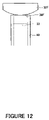
- FIG. 12 is a diagram of an ink supply tube contacting a valve member, according to an embodiment of the present invention.
- FIG. 13 is a diagram of an ink supply tube contacting a valve member, according to another embodiment of the present invention.
- FIG. 14 is a diagram of a projecting portion of a valve member entering the interior of an ink supply tube, according to another embodiment of the present invention.
- FIG. 15 is a diagram of a projecting portion of a valve member entering the interior of an ink supply tube, according to yet another embodiment of the present invention.
- FIG. 16 is a diagram of a projecting portion of a valve member entering the interior of an ink supply tube, according to still another embodiment of the present invention.
- FIG. 17 is a diagram of a projecting portion of a valve member entering the interior of an ink supply tube, according to still yet another embodiment of the present invention.
- FIG. 18 is a diagram of a projecting portion of a valve member entering the interior of an ink supply tube, according to a further embodiment of the present invention.
- FIG. 19 is a diagram of a projecting portion of a valve member entering the interior of an ink supply tube, according to yet a further embodiment of the present invention.
- FIG. 20 is a diagram of a projecting portion of a valve member entering the interior of an ink supply tube, according to still a further embodiment of the present invention.
- FIG. 21 is a diagram of a projecting portion of a valve member entering the interior of an ink supply tube, according to still yet a further embodiment of the present invention.
- FIG. 22 is a perspective view of a valve member, according to still another embodiment of the present invention.
- FIG. 23 is a cross-sectional view of a valve member in a state in which a projecting portion enters the interior of an ink supply tube, according to still yet another embodiment of the present invention.
- FIGS. 1-23 like numerals being used for like corresponding parts in the various drawings.
- an inkjet printer 100 may comprise a carriage 1 which may be configured to linearly reciprocate in a predetermined direction along a guide 6 .
- Inkjet printer 100 may also comprise an inkjet head 2 mounted to carriage 1 .
- Inkjet head 2 may comprise a plurality of nozzles configured to discharge ink onto a printing paper 2 .
- inkjet head 2 may comprise four types of nozzles, and the nozzles may be configured to dispense cyan (C) colored ink, yellow (Y) colored ink, magenta (M) colored ink, and black (K) colored ink, respectively, onto printing paper P.
- inkjet printer 100 may comprise an ink supply device 3 configured to supply ink to inkjet head 2 , and a transporting device 4 configured to feed printing paper P in a direction which is orthogonal to the direction of movement of inkjet head 2 , and is parallel to an ink discharge surface 2 a of inkjet head 2 .
- Inkjet head 2 and holders 11 of ink supply device 3 may be connected to each other via supply tubes 7 .
- Inkjet printer 100 may eject ink toward printing paper P while inkjet head 2 reciprocates in the predetermined direction, and printing paper P may move in the left-and-right direction in FIG. 1 , such that a desired image may be formed on printing paper P.
- Ink supply device 3 may comprise at least one ink cartridge 10 and at least one holder 11 , and each ink cartridge 10 may be configured to be mounted to and demounted from a corresponding holder 11 .
- ink supply device may comprise four ink cartridges 10 , and ink cartridges 10 may contain cyan (C) colored ink, yellow (Y) colored ink, magenta (M) colored ink, and black (K) colored ink, respectively.
- the number of holders 11 may correspond to the number of ink cartridges 10 .
- ink cartridge 10 may comprises a cartridge body 20 .
- Cartridge body 20 may comprise a body member 21 configured to store ink, and a cap 22 .
- Cap 22 may be positioned at the lower end of body member 21
- body member 21 may comprise an ink storage section 23 and a cylindrical portion 24 .
- Ink storage section 23 may have a substantially vertically elongated parallelepiped shape, and cylindrical portion 24 may extend downward from the lower end of ink storage section 23 .
- Ink storage section 23 and cylindrical portion 24 may be formed integrally, e.g., may be integrally molded.
- Ink storage section 23 may comprise an ink storage chamber 25 configured to store ink, and an atmospheric air communication hole 26 may be formed through an upper wall of ink storage section 23 .
- Atmospheric air communication hole 26 may be configured to communicate ink storage chamber 25 with atmospheric air.
- An ink discharge hole 27 may be formed through a lower wall of ink storage section 23 , and ink storage chamber 25 and a space within cylindrical portion 24 may be in communication with each other via ink discharge hole 27 . Therefore, atmospheric air may be introduced through atmospheric air communication hole 26 into ink storage chamber 25 , and ink in ink storage chamber 25 may be discharged through ink discharge hole 27 into the space within cylindrical portion 24 .
- a tab 28 may be integrally formed at an upper end portion of body member 21 .
- Cap 22 may be attached to the lower end portion of cylindrical portion 24 , and cap 22 may close the space within cylindrical portion 24 from below.
- An ink introduction hole 29 may be formed through the center of the bottom portion of cap 22 . Referring to FIGS. 5 and 6 , when ink cartridge 10 is mounted to holder 11 and an ink supply tube 40 provided on holder 11 is inserted into ink introduction hole 29 , ink may flow out from the space within cylindrical portion 24 to ink supply tube 40 .
- ink introduction hole 29 may have a tapered shape, such that the diameter of introduction hole 29 increases as it approaches ink supply tube 40 .
- cap 22 may comprise an annular valve seat 30 on the bottom surface of cap 22 .
- Annular valve seat 30 may project upward and surround introduction hole 29 .
- Cylindrical portion 24 may comprise a valve member 31 configured to move in the vertical direction.
- valve member 31 may comprise a disc-shaped valve body 32 and a projecting portion 33 . Projecting portion 33 may project from the center of the lower surface of valve body 32 downward in a direction orthogonal to the lower surface of valve body 32 .
- Valve body 32 and projecting portion 33 may be formed integrally, e.g., may be integrally molded.
- Valve member 31 may open ink introduction hole 29 when there is a gap between valve member 31 and valve seat 30 , and may close ink introduction hole 29 when valve member 31 is in tight contact with valve seat 30 .
- a resilient member 37 may be disposed on the upper side of valve member 31 , and valve member 31 may be urged toward valve seat 30 by resilient member 37 . Therefore, when ink cartridge 10 is not mounted, valve member 31 may be pressed against valve seat 30 by an urging force of resilient member 37 , such that ink introduction hole 29 is closed.
- Cap 22 may comprise a flexible material, e.g., rubber or elastomer, such that the contact between valve member 31 and valve seat 30 may be enhanced to reliably close ink introduction hole 29 .
- projecting portion 33 may enter the interior of ink supply tube 40 .
- the shape of the projecting portion 33 when viewed from below may be a cross-shape.
- Projecting portion 33 may comprise a distal end and a peripheral surface connecting the lower surface of valve body 32 and the distal end of projecting portion 33 .
- the peripheral surface of projecting portion 33 may comprise a plurality of contacting portions 34 , e.g., four contacting portions 34 , arranged at regular intervals in a circumferential direction of projecting portion 33 .
- contacting portions 34 may contact the inner surface of ink supply tube 40 .
- portions of the peripheral surface of projecting portion 33 arranged respectively between the adjacent ones of contacting portions 34 in the circumferential direction may be non-contacting portions 35 which do not contact the inner surface of ink supply tube 40 .
- ink supply tube 40 When ink cartridge 10 is mounted to holder 11 , the distal end of ink supply tube 40 may contact a pressed portion 36 of the lower surface of valve body 32 , and pressed portion 36 may be pressed upward by ink supply tube 40 , such that ink introduction hole 29 is opened.
- holder 11 may comprise ink supply tube 40 extending upward from the bottom portion of holder 11 .
- a pair of notches 41 may be formed through ink supply tube 40 .
- Notches 41 may extend from the distal end of ink supply tube 40 in the axial direction of ink supply tube 40 .
- An ink supply channel 42 may be formed in the bottom portion of holder 11 , and ink supply channel 42 may continue from the lower end of ink supply tube 40 and may be connected to inkjet head 2 via supply tube 7 .
- ink supply tube 40 may be inserted into ink introduction hole 29 , such that the distal end of ink supply tube 40 presses pressed portion 36 of valve member 31 upward.
- projecting portion 33 on valve member 31 may enter ink supply tube 40 .
- a valve member 44 may be positioned in the vicinity of a connecting portion 43 between ink supply tube 40 and ink supply channel 42 .
- Valve member 44 may be configured to move in the vertical direction.
- a valve rod 45 may extend from the upper surface of valve member 44 upward within ink supply tube 40 .
- the distal end of valve rod 45 may be positioned within ink supply tube 40 irrespective of the position of valve member 44 , and valve rod 45 may not project upward from ink supply tube 40 even when valve member 44 is moved in the vertical direction.
- An O-ring 46 may comprise a flexible material, such as rubber, and may be mounted to the upper surface of valve member 44 . Referring to FIG.
- valve member 44 contacts the inner wall portion of ink supply channel 42 via O-ring 46 , a communication path between ink supply tube 40 and ink supply channel 42 through connecting portion 43 is closed.
- the communication path is open.
- a spring 47 may be positioned on the lower side of valve member 44 , and valve member 44 is urged upward by spring 47 . Therefore, when ink cartridge 10 is not mounted to holder 11 , valve member 44 may be pressed against the inner wall portion near connecting portion 43 by an urging force of spring 47 , and the communication path between ink supply tube 40 and ink supply channel 42 through connecting portion 43 is closed.
- valve member 31 When ink cartridge 10 is mounted to holder 11 , valve member 31 may enter the interior of ink supply tube 40 , valve member 44 may be pressed downward against the urging force of spring 47 by projecting portion 33 of valve member 31 , and valve member 44 may separate from the inner wall portion, such that ink supply channel 42 communicates with the interior of ink supply tube 40 .
- the urging force of spring 47 to urge valve member 44 upward before ink cartridge 10 is mounted to holder 11 may be less than an urging force of resilient member 37 to urge valve member 31 downward.
- valve member 31 when ink cartridge 10 is not mounted to holder 11 , valve member 31 may be urged downward by resilient member 37 and may be pressed against valve seat 30 within ink cartridge 10 , and ink introduction hole 29 may be closed by valve member 31 .
- valve member 44 in the holder 11 , valve member 44 may be urged upward by spring 47 , and O-ring 46 may be pressed against the inner wall portion of ink supply channel 42 in the vicinity of connecting portion 43 , such that valve member 44 prevents communication between ink supply tube 40 and ink supply channel 42 via connecting portion 43 . Therefore, ink may not leak from ink cartridge 10 or ink supply tube 40 , and air may not enter ink cartridge 10 or ink supply tube 40 .
- ink supply tube 40 may be inserted into introduction hole 29 , and projecting portion 33 of valve member 31 may enter the interior of ink supply tube 40 and may contact the distal end of valve rod 45 positioned within ink supply tube 40 .
- the urging force of spring 47 in holder 11 to urge valve member 44 upward may be less than the urging force of resilient member 37 in ink cartridge 10 to urge valve member 31 downward. Therefore, when ink cartridge 10 is pressed inwardly of holder 11 , valve member 44 may be pressed downward against the urging force of spring 47 by projecting portion 33 .
- O-ring 46 may separate from the inner wall portion in the vicinity of connecting portion 43 between ink supply tube 40 and ink supply channel 42 , such that ink supply tube 40 and ink supply channel 42 may communicate with each other via connecting portion 43 .
- contacting portions 34 may contact the inner surface of ink supply tube 40 , and the motion of projecting portion 33 entering ink supply tube 40 may be guided by contacting portions 34 .
- valve member 31 may separate from valve seat 30 formed on cap 22 , such that ink introduction hole 29 is opened.
- ink in cylindrical portion 24 of ink cartridge 10 may flow into ink supply channel 42 via notches 41 formed at the distal end of ink supply tube 40 and via the passages provided between non-contacting portions 35 and the inner surface of ink supply tube 40 .
- the ink may be further supplied to inkjet head 2 via ink supply channel 42 .
- ink introduction hole 29 of ink cartridge 10 and ink supply channel 42 of holder 11 may be respectively opened only when ink cartridge 10 is mounted to holder 11 , when ink cartridge 10 is not mounted to holder 11 , ink does not leak from ink cartridge 10 or ink supply tube 40 of holder 11 , and air does not enter the interior of ink cartridge 10 or ink supply tube 40 .
- pressed portion 36 of valve member 31 is pressed by the distal end of ink supply tube 40 and ink introduction hole 29 is opened, a specific member for pressing valve member 31 to open ink introduction hole 29 is not necessary, which reduces the number of components which reduces manufacturing costs.
- valve rod 45 of valve member 44 is positioned in the interior of ink supply tube 40 , and does not project out from ink supply tube 40 , valve member 44 may be prevented from being pressed downward when ink cartridge 10 is not mounted to holder 11 . Therefore, the communication between ink supply tube 40 and ink supply channel 42 through connecting portion 43 may be prevented when ink cartridge 10 is not mounted to holder 11 . Further, the motion of projecting portion 33 entering ink supply tube 40 may be guided by four contacting portions 34 , such that mounting of ink cartridge 10 may be performed reliably.
- contacting portions 34 may provided at regular intervals in a circumferential direction of projecting portion 33 , the motion of projecting portion 33 entering ink supply tube 40 may be guided uniformly at the circumference, such that mounting of ink cartridge 10 may be performed reliably.
- non-contacting portions 35 which do not contact the inner surface of ink supply tube 40 may be also provided on the peripheral surface of the projecting portion 33 , the ink passages may be securely provided between the inner surface of ink supply tube 40 and non-contacting portion 35 when projecting portion 33 of valve member 31 enters the interior of ink supply tube 40 . Therefore, even when the diameter of ink supply tube 40 is reduced, ink may flow into ink supply tube 40 .
- ink supply tube 40 By reducing the diameter of ink supply tube 40 in this manner, the contact surface area between ink supply tube 40 and ink introduction hole 29 may be reduced. Resistance when ink cartridge 10 is mounted and demounted may be reduced, and mounting and demounting of ink cartridge 10 may be facilitated. When the diameter of ink supply tube 40 is reduced, the amount of leakage of ink or entrance of air at the time of mounting and demounting of ink cartridge 10 may also be reduced.
- non-contacting portions 35 may be arranged respectively between the adjacent ones of contacting portions 34 provided at regular intervals in a circumferential direction of projecting portion 33 , the ink passages between ink supply tube 40 and non-contacting portions 35 may be symmetrical with respect to the axis of ink supply tube 40 , such that ink may flow smoothly in ink supply tube 40 .
- the distal end surface of an ink supply tube 40 A may have an inclined surface, which may form an angle other than 90° with respect to the axial direction of tube 40 A.
- a protrusion 41 B which projects in the axial direction of an ink supply tube 40 B from the distal end surface thereof may be formed.
- the distal end surface of an ink supply tube may be entirely convex or concave. In these cases, when the distal end of the ink supply tube contacts the flat lower surface (pressed portion) of the valve body, a gap may be formed between the ink supply tube and the valve body. Therefore, ink may flow into the ink supply tube via the gap.
- a protrusion may be formed on the lower surface of the valve body of the valve member of the cartridge, and the protrusion may protrude from the lower surface less further than the projecting portion protrudes, such that the protrusion may be pressed upward by the ink supply tube as the pressed portion.
- a pair of parallelepiped protrusions 36 C may be formed on the lower surface of a valve body 32 C at positions in point symmetrical with respect to a center axis of a projecting portion 33 C. Protrusions 36 C protrude from the lower surface less further than projecting portion 33 C protrudes. Referring to FIG.
- a plurality of column shaped protrusions 36 D may be formed at regular intervals circumferentially around projecting portion 33 D on the lower surface of valve body 32 D.
- a gap may be formed between the lower surface of the valve body and the distal end surface of the ink supply tube, whereby ink may flow into the interior of the ink supply tube via the gap.
- the protrusion as the pressed portion is not limited to the parallelepiped shape or the column shape, and those in various shapes may be employed.
- the number of the protrusions also may be varied, and the plurality of protrusions may be arranged respectively at regular intervals circumferentially around the projecting portion. In this case, the distal end of the ink supply tube may contact the plurality of protrusions, such that the valve member may be pressed stably, and the mounting of the ink cartridge may be performed more reliably.
- At least one groove 50 may be formed in a pressed portion 36 E on the lower surface of a valve body 32 E.
- Groove 50 may extend from a position adjacent to the center of a projecting portion 33 E to the peripheral surface of valve body 32 E.
- the number of the grooves 50 employed may be any number of grooves. In this case, when the ink supply tube contacts pressed portion 36 E of valve body 32 E, ink may flow into the interior of the ink supply tube via groove 50 .
- the surface of the pressed portion of the valve body to be pressed by the ink supply tube may have a curved shape.
- the surface of a pressed portion 36 F of a valve body 32 F may be convex, or the surface of a pressed portion 36 G of a valve body 32 G may be concave.
- a gap may be formed between the valve body and the distal end surface of the ink supply tube, whereby ink may flow into the interior of the ink supply tube via the gap.
- a plurality of non-contacting portions 35 H e.g., four non-contacting portions, arranged respectively between the adjacent ones of contacting portions 34 H circumferentially of a projecting portion 33 H each may be formed into a rounded recess when viewed in the direction that projecting portion 33 H projects.
- Contacting portions 34 H may be configured to contact the interior of ink supply tube 40 and non-contacting portions 35 H may not.
- the number of the contacting portions and the non-contacting portions arranged respectively between the adjacent contacting portions may be any number.
- three contacting portions 34 I and three non-contacting portions 35 I may be provided on a projecting portion 331 .
- a non-contacting portion 35 J may be formed by removing a projecting portion 33 J from the periphery surface to the axial center portion of projecting portion 33 J. The remaining portion on the peripheral surface of the projecting portion 33 J may serve as a contacting portion 34 J configured to contact the interior of ink supply tube 40 .
- contacting portions 34 K configured to contact the interior of ink supply tube 40 may have an arc shape when viewed in the direction that a projecting portion 33 K projects.
- projecting portions 33 L, 33 M, 33 N, 33 O may be formed by partly removing the peripheral surface of a column when viewed in the direction that projections project, such that the removed portions may serve as non-contacting portions 35 L, 35 M, 35 N, and 35 O, and the remaining portions may serve as contacting portions 34 L, 34 M, 34 N, and 34 O.
- the plurality of contacting portions may be provided respectively at regular intervals in a circumferential direction of the projecting portion as shown in FIGS. 4 , 14 , 15 , 17 , and 19 - 21 .
- the area of the contacting portions may be greater than the area of the non-contacting portions, as shown in FIGS. 16 and 18 .
- protrusions 36 P as the pressed portions may be provided on the lower surface of a valve body 32 P at positions around a projecting portion 33 P, and a through hole 60 may be formed through projecting portion 33 P.
- through hole 60 may extend from the distal end of projecting portion 33 P through the interior of projecting portion 33 P and reach the peripheral surface of projecting portion 339 at the boundary between projecting portion 33 P and the lower surface of valve body 32 P.
- a passage from the ink cartridge to the interior of ink supply tube 40 may be provided by a gap formed between the lower surface of valve body 32 P and ink supply tube 40 and through hole 60 formed within projecting portion 33 P.
- the projecting portion 33 P may be formed into a column shape that contacts the inner surface of ink supply tube 40 over the entire peripheral surface thereof.
- valve member 44 may comprise a valve rod 45 positioned within ink supply tube 40 , such that when valve rod 45 is pressed downward by projecting portion 33 of valve member 31 , valve member 44 may allow communication therebetween. Nevertheless, valve rod 45 may be omitted, and valve member 44 of holder 11 may be directly pressed by projecting portion 33 of valve member 31 . In this case, because valve member 44 may be positioned within ink supply channel 42 , valve member 44 may be prevented from being erroneously pressed when the ink cartridge is not mounted to the holder.
- the ink cartridge may be mounted and demounted in the vertical direction with respect to the holder. Nevertheless, the ink supply tube of the holder may extend in the horizontal direction and the ink cartridge may be mounted and demounted with respect to the holder in the horizontal direction.
Landscapes
- Ink Jet (AREA)
Applications Claiming Priority (2)
| Application Number | Priority Date | Filing Date | Title |
|---|---|---|---|
| JP2005-377009 | 2005-12-28 | ||
| JP2005377009A JP2007175998A (ja) | 2005-12-28 | 2005-12-28 | インクカートリッジ、インクジェットプリンタ、及び、インク供給装置 |
Publications (2)
| Publication Number | Publication Date |
|---|---|
| US20070176987A1 US20070176987A1 (en) | 2007-08-02 |
| US7597433B2 true US7597433B2 (en) | 2009-10-06 |
Family
ID=37831824
Family Applications (1)
| Application Number | Title | Priority Date | Filing Date |
|---|---|---|---|
| US11/616,321 Expired - Fee Related US7597433B2 (en) | 2005-12-28 | 2006-12-27 | Ink cartridge, inkjet printer and combination thereof |
Country Status (5)
| Country | Link |
|---|---|
| US (1) | US7597433B2 (de) |
| EP (1) | EP1803569B1 (de) |
| JP (1) | JP2007175998A (de) |
| CN (1) | CN1990256B (de) |
| AT (1) | ATE516148T1 (de) |
Cited By (2)
| Publication number | Priority date | Publication date | Assignee | Title |
|---|---|---|---|---|
| US20080158315A1 (en) * | 2006-12-28 | 2008-07-03 | Brother Kogyo Kabushiki Kaisha | Ink supply device and inkjet image recording device |
| US20100002061A1 (en) * | 2008-07-03 | 2010-01-07 | Olympus Corporation | Connection mechanism and ink supply apparatus equipped with connection mechanism |
Families Citing this family (7)
| Publication number | Priority date | Publication date | Assignee | Title |
|---|---|---|---|---|
| JPWO2010082296A1 (ja) * | 2009-01-13 | 2012-06-28 | 株式会社ミマキエンジニアリング | バルクインク供給システム |
| JP5195561B2 (ja) * | 2009-03-23 | 2013-05-08 | ブラザー工業株式会社 | 液体容器 |
| JP6398274B2 (ja) * | 2014-04-11 | 2018-10-03 | セイコーエプソン株式会社 | 液体容器、アダプター、ならびに液体噴射装置 |
| JP6676927B2 (ja) * | 2015-10-30 | 2020-04-08 | セイコーエプソン株式会社 | 液体噴射装置 |
| JP7031182B2 (ja) * | 2017-09-08 | 2022-03-08 | ブラザー工業株式会社 | インクジェット記録装置 |
| JP7622417B2 (ja) | 2020-12-17 | 2025-01-28 | セイコーエプソン株式会社 | カートリッジ、印刷装置、および、印刷システム |
| JP7661802B2 (ja) * | 2021-06-16 | 2025-04-15 | セイコーエプソン株式会社 | カートリッジ |
Citations (9)
| Publication number | Priority date | Publication date | Assignee | Title |
|---|---|---|---|---|
| JPH05301350A (ja) | 1992-04-27 | 1993-11-16 | Fuji Xerox Co Ltd | インクジェット記録装置のインク供給機構 |
| JPH0796302B2 (ja) | 1986-07-04 | 1995-10-18 | キヤノン株式会社 | インク供給装置 |
| US6130695A (en) | 1995-04-27 | 2000-10-10 | Hewlett-Packard Company | Ink delivery system adapter |
| JP2003034038A (ja) | 2001-07-23 | 2003-02-04 | Seiko Epson Corp | カートリッジ装置及びこれを備えたプリンタ |
| JP2004216607A (ja) | 2003-01-10 | 2004-08-05 | Seiko Epson Corp | インクジェット式記録装置 |
| JP2004216608A (ja) | 2003-01-10 | 2004-08-05 | Seiko Epson Corp | インクジェット式記録装置 |
| US20050146577A1 (en) | 2003-11-25 | 2005-07-07 | Brother Kogyo Kabushiki Kaisha | Ink cartridge |
| US7011397B2 (en) * | 2002-09-12 | 2006-03-14 | Seiko Epson Corporation | Ink cartridge and method of regulating fluid flow |
| US7237882B2 (en) * | 2001-04-03 | 2007-07-03 | Seiko Epson Corporation | Ink cartridge having retaining structure and recording apparatus for receiving the ink cartridge |
-
2005
- 2005-12-28 JP JP2005377009A patent/JP2007175998A/ja active Pending
-
2006
- 2006-12-21 AT AT06026598T patent/ATE516148T1/de not_active IP Right Cessation
- 2006-12-21 EP EP06026598A patent/EP1803569B1/de not_active Not-in-force
- 2006-12-22 CN CN2006101711311A patent/CN1990256B/zh not_active Expired - Fee Related
- 2006-12-27 US US11/616,321 patent/US7597433B2/en not_active Expired - Fee Related
Patent Citations (9)
| Publication number | Priority date | Publication date | Assignee | Title |
|---|---|---|---|---|
| JPH0796302B2 (ja) | 1986-07-04 | 1995-10-18 | キヤノン株式会社 | インク供給装置 |
| JPH05301350A (ja) | 1992-04-27 | 1993-11-16 | Fuji Xerox Co Ltd | インクジェット記録装置のインク供給機構 |
| US6130695A (en) | 1995-04-27 | 2000-10-10 | Hewlett-Packard Company | Ink delivery system adapter |
| US7237882B2 (en) * | 2001-04-03 | 2007-07-03 | Seiko Epson Corporation | Ink cartridge having retaining structure and recording apparatus for receiving the ink cartridge |
| JP2003034038A (ja) | 2001-07-23 | 2003-02-04 | Seiko Epson Corp | カートリッジ装置及びこれを備えたプリンタ |
| US7011397B2 (en) * | 2002-09-12 | 2006-03-14 | Seiko Epson Corporation | Ink cartridge and method of regulating fluid flow |
| JP2004216607A (ja) | 2003-01-10 | 2004-08-05 | Seiko Epson Corp | インクジェット式記録装置 |
| JP2004216608A (ja) | 2003-01-10 | 2004-08-05 | Seiko Epson Corp | インクジェット式記録装置 |
| US20050146577A1 (en) | 2003-11-25 | 2005-07-07 | Brother Kogyo Kabushiki Kaisha | Ink cartridge |
Non-Patent Citations (1)
| Title |
|---|
| European Patent Office, European Search Report for EP Appl'n. No. 06026598 (counterpart to above-captioned patent appl'n) mailed Mar. 23, 2007. |
Cited By (4)
| Publication number | Priority date | Publication date | Assignee | Title |
|---|---|---|---|---|
| US20080158315A1 (en) * | 2006-12-28 | 2008-07-03 | Brother Kogyo Kabushiki Kaisha | Ink supply device and inkjet image recording device |
| US8152286B2 (en) * | 2006-12-28 | 2012-04-10 | Brother Kogyo Kabushiki Kaisha | Ink supply device and inkjet image recording device |
| US20100002061A1 (en) * | 2008-07-03 | 2010-01-07 | Olympus Corporation | Connection mechanism and ink supply apparatus equipped with connection mechanism |
| US8075113B2 (en) * | 2008-07-03 | 2011-12-13 | Ortek Corporation | Connection mechanism and ink supply apparatus equipped with connection mechanism |
Also Published As
| Publication number | Publication date |
|---|---|
| CN1990256A (zh) | 2007-07-04 |
| ATE516148T1 (de) | 2011-07-15 |
| CN1990256B (zh) | 2010-07-21 |
| US20070176987A1 (en) | 2007-08-02 |
| JP2007175998A (ja) | 2007-07-12 |
| EP1803569B1 (de) | 2011-07-13 |
| EP1803569A1 (de) | 2007-07-04 |
Similar Documents
| Publication | Publication Date | Title |
|---|---|---|
| EP3939794B1 (de) | Flüssigkeitsaufbewahrungsbehälter | |
| KR102945764B1 (ko) | 액체 수용 용기 | |
| US10427412B2 (en) | Liquid ejecting apparatus and liquid refilling container | |
| US7753505B2 (en) | Ink cartridges and inkjet printers | |
| US8272724B2 (en) | Liquid containers | |
| US7997705B2 (en) | Ink cartridges and ink supply systems | |
| US7914134B2 (en) | Ink cartridges and inkjet printers | |
| US12168352B2 (en) | Liquid storage container | |
| US7597433B2 (en) | Ink cartridge, inkjet printer and combination thereof | |
| US20230302806A1 (en) | Cartridge and printing apparatus | |
| EP4151419B1 (de) | Tintennachfüllbehälter | |
| US7354143B2 (en) | Inkjet recording apparatus | |
| US9150028B2 (en) | Liquid cartridge capable of reducing force required to open air channel and liquid channel | |
| US6588874B2 (en) | Airtight elastic cap of ink-jet recording head, storage container, and ink-jet recording apparatus | |
| US12172447B2 (en) | Ink replenishment container | |
| US20250042173A1 (en) | Liquid cartridge | |
| US20250042162A1 (en) | Liquid cartridge | |
| US20260054488A1 (en) | Ink supply container | |
| CN100542819C (zh) | 墨盒和喷墨打印机 | |
| JP2024165709A (ja) | インク補給容器 | |
| HK1091442B (en) | Ink cartridge |
Legal Events
| Date | Code | Title | Description |
|---|---|---|---|
| AS | Assignment |
Owner name: BROTHER KOGYO KABUSHIKI KAISHA, JAPAN Free format text: ASSIGNMENT OF ASSIGNORS INTEREST;ASSIGNORS:TANAHASHI, NAOKAZU;ITO, SHINGO;SUGIYAMA, WATARU;AND OTHERS;REEL/FRAME:018678/0559;SIGNING DATES FROM 20061211 TO 20061212 |
|
| STCF | Information on status: patent grant |
Free format text: PATENTED CASE |
|
| FPAY | Fee payment |
Year of fee payment: 4 |
|
| FPAY | Fee payment |
Year of fee payment: 8 |
|
| FEPP | Fee payment procedure |
Free format text: MAINTENANCE FEE REMINDER MAILED (ORIGINAL EVENT CODE: REM.); ENTITY STATUS OF PATENT OWNER: LARGE ENTITY |
|
| LAPS | Lapse for failure to pay maintenance fees |
Free format text: PATENT EXPIRED FOR FAILURE TO PAY MAINTENANCE FEES (ORIGINAL EVENT CODE: EXP.); ENTITY STATUS OF PATENT OWNER: LARGE ENTITY |
|
| STCH | Information on status: patent discontinuation |
Free format text: PATENT EXPIRED DUE TO NONPAYMENT OF MAINTENANCE FEES UNDER 37 CFR 1.362 |
|
| FP | Lapsed due to failure to pay maintenance fee |
Effective date: 20211006 |