US7611657B2 - Mold clamp assembly for blow molding machine and method - Google Patents
Mold clamp assembly for blow molding machine and method Download PDFInfo
- Publication number
- US7611657B2 US7611657B2 US11/564,949 US56494906A US7611657B2 US 7611657 B2 US7611657 B2 US 7611657B2 US 56494906 A US56494906 A US 56494906A US 7611657 B2 US7611657 B2 US 7611657B2
- Authority
- US
- United States
- Prior art keywords
- mold
- drive
- frame
- mold halves
- clamp assembly
- Prior art date
- Legal status (The legal status is an assumption and is not a legal conclusion. Google has not performed a legal analysis and makes no representation as to the accuracy of the status listed.)
- Active, expires
Links
- 238000000071 blow moulding Methods 0.000 title claims abstract description 25
- 238000000034 method Methods 0.000 title claims description 9
- 230000005540 biological transmission Effects 0.000 claims description 3
- 238000001125 extrusion Methods 0.000 description 7
- 230000000712 assembly Effects 0.000 description 6
- 238000000429 assembly Methods 0.000 description 6
- 238000005452 bending Methods 0.000 description 6
- 238000001816 cooling Methods 0.000 description 2
- 238000000465 moulding Methods 0.000 description 2
- 230000004075 alteration Effects 0.000 description 1
- 238000007664 blowing Methods 0.000 description 1
- 230000004048 modification Effects 0.000 description 1
- 238000012986 modification Methods 0.000 description 1
Images




Classifications
-
- B—PERFORMING OPERATIONS; TRANSPORTING
- B29—WORKING OF PLASTICS; WORKING OF SUBSTANCES IN A PLASTIC STATE IN GENERAL
- B29C—SHAPING OR JOINING OF PLASTICS; SHAPING OF MATERIAL IN A PLASTIC STATE, NOT OTHERWISE PROVIDED FOR; AFTER-TREATMENT OF THE SHAPED PRODUCTS, e.g. REPAIRING
- B29C49/00—Blow-moulding, i.e. blowing a preform or parison to a desired shape within a mould; Apparatus therefor
- B29C49/42—Component parts, details or accessories; Auxiliary operations
- B29C49/56—Opening, closing or clamping means
- B29C49/5601—Mechanically operated, i.e. closing or opening of the mould parts is done by mechanic means
- B29C49/5602—Mechanically operated, i.e. closing or opening of the mould parts is done by mechanic means using cams
-
- B—PERFORMING OPERATIONS; TRANSPORTING
- B29—WORKING OF PLASTICS; WORKING OF SUBSTANCES IN A PLASTIC STATE IN GENERAL
- B29C—SHAPING OR JOINING OF PLASTICS; SHAPING OF MATERIAL IN A PLASTIC STATE, NOT OTHERWISE PROVIDED FOR; AFTER-TREATMENT OF THE SHAPED PRODUCTS, e.g. REPAIRING
- B29C49/00—Blow-moulding, i.e. blowing a preform or parison to a desired shape within a mould; Apparatus therefor
- B29C49/02—Combined blow-moulding and manufacture of the preform or the parison
- B29C49/04—Extrusion blow-moulding
-
- B—PERFORMING OPERATIONS; TRANSPORTING
- B29—WORKING OF PLASTICS; WORKING OF SUBSTANCES IN A PLASTIC STATE IN GENERAL
- B29C—SHAPING OR JOINING OF PLASTICS; SHAPING OF MATERIAL IN A PLASTIC STATE, NOT OTHERWISE PROVIDED FOR; AFTER-TREATMENT OF THE SHAPED PRODUCTS, e.g. REPAIRING
- B29C49/00—Blow-moulding, i.e. blowing a preform or parison to a desired shape within a mould; Apparatus therefor
- B29C49/28—Blow-moulding apparatus
- B29C49/30—Blow-moulding apparatus having movable moulds or mould parts
- B29C49/32—Blow-moulding apparatus having movable moulds or mould parts moving "to and fro"
-
- B—PERFORMING OPERATIONS; TRANSPORTING
- B29—WORKING OF PLASTICS; WORKING OF SUBSTANCES IN A PLASTIC STATE IN GENERAL
- B29C—SHAPING OR JOINING OF PLASTICS; SHAPING OF MATERIAL IN A PLASTIC STATE, NOT OTHERWISE PROVIDED FOR; AFTER-TREATMENT OF THE SHAPED PRODUCTS, e.g. REPAIRING
- B29C49/00—Blow-moulding, i.e. blowing a preform or parison to a desired shape within a mould; Apparatus therefor
- B29C49/28—Blow-moulding apparatus
- B29C49/30—Blow-moulding apparatus having movable moulds or mould parts
- B29C49/36—Blow-moulding apparatus having movable moulds or mould parts rotatable about one axis
-
- B—PERFORMING OPERATIONS; TRANSPORTING
- B29—WORKING OF PLASTICS; WORKING OF SUBSTANCES IN A PLASTIC STATE IN GENERAL
- B29C—SHAPING OR JOINING OF PLASTICS; SHAPING OF MATERIAL IN A PLASTIC STATE, NOT OTHERWISE PROVIDED FOR; AFTER-TREATMENT OF THE SHAPED PRODUCTS, e.g. REPAIRING
- B29C49/00—Blow-moulding, i.e. blowing a preform or parison to a desired shape within a mould; Apparatus therefor
- B29C49/42—Component parts, details or accessories; Auxiliary operations
- B29C49/56—Opening, closing or clamping means
- B29C49/5601—Mechanically operated, i.e. closing or opening of the mould parts is done by mechanic means
- B29C49/5603—Mechanically operated, i.e. closing or opening of the mould parts is done by mechanic means using toggle mechanism
-
- B—PERFORMING OPERATIONS; TRANSPORTING
- B29—WORKING OF PLASTICS; WORKING OF SUBSTANCES IN A PLASTIC STATE IN GENERAL
- B29C—SHAPING OR JOINING OF PLASTICS; SHAPING OF MATERIAL IN A PLASTIC STATE, NOT OTHERWISE PROVIDED FOR; AFTER-TREATMENT OF THE SHAPED PRODUCTS, e.g. REPAIRING
- B29C49/00—Blow-moulding, i.e. blowing a preform or parison to a desired shape within a mould; Apparatus therefor
- B29C49/42—Component parts, details or accessories; Auxiliary operations
- B29C49/56—Opening, closing or clamping means
- B29C49/5606—Pneumatically operated, i.e. closing or opening of the mould parts is done by hydraulic means
-
- B—PERFORMING OPERATIONS; TRANSPORTING
- B29—WORKING OF PLASTICS; WORKING OF SUBSTANCES IN A PLASTIC STATE IN GENERAL
- B29C—SHAPING OR JOINING OF PLASTICS; SHAPING OF MATERIAL IN A PLASTIC STATE, NOT OTHERWISE PROVIDED FOR; AFTER-TREATMENT OF THE SHAPED PRODUCTS, e.g. REPAIRING
- B29C49/00—Blow-moulding, i.e. blowing a preform or parison to a desired shape within a mould; Apparatus therefor
- B29C49/42—Component parts, details or accessories; Auxiliary operations
- B29C49/56—Opening, closing or clamping means
- B29C49/5607—Electrically operated, e.g. the closing or opening is done with an electrical motor direct drive
-
- B—PERFORMING OPERATIONS; TRANSPORTING
- B29—WORKING OF PLASTICS; WORKING OF SUBSTANCES IN A PLASTIC STATE IN GENERAL
- B29C—SHAPING OR JOINING OF PLASTICS; SHAPING OF MATERIAL IN A PLASTIC STATE, NOT OTHERWISE PROVIDED FOR; AFTER-TREATMENT OF THE SHAPED PRODUCTS, e.g. REPAIRING
- B29C49/00—Blow-moulding, i.e. blowing a preform or parison to a desired shape within a mould; Apparatus therefor
- B29C49/42—Component parts, details or accessories; Auxiliary operations
- B29C49/56—Opening, closing or clamping means
- B29C49/561—Characterised by speed, e.g. variable opening closing speed
Definitions
- the invention relates to mold clamp assemblies for blow molding machines and to related methods.
- Conventional mold clamp assemblies for rotary-type blow molding machines and for shuttle-type blow molding machines are mounted on the frame of the machine supporting the assembly and, when actuated, transmit clamping force from a drive on one side of the mold to the other side of the mold through the frame.
- This means that the frame supporting the molds must be sufficiently strong to counteract bending moments imposed by the high clamp force transmitted through the frame. Deformation of the frame by the clamp force is impermissible because deformation would not permit the mold faces to close parallel with one another.
- the invention is an improved mold clamp assembly and method for rotary-type and shuttle-type blow molding machines.
- the blow molding machine includes an extendable and retractable drive located to one side of the mold halves.
- the drive is directly connected to the adjacent mold half and is connected to the remote mold half through a shift rod and a pivot arm mechanism free of the frame.
- the support for the pivot arm is connected directly to the extendable and retractable drive by a tension member apart from the machine frame. In this way, opposed clamp forces required to hold the mold closed during molding are transmitted directly from the drive to the mold halves.
- the drive is extended and retracted to open and close the mold halves. Clamp forces are not transmitted through the machine frame and do not subject the frame to bending moments.
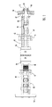
- FIG. 1 is a side view of a first embodiment mold clamp assembly for a rotary-type blow molding machine with the mold closed;
- FIG. 2 is a view like FIG. 1 with the mold open;
- FIG. 3 is a view taken generally along line 3 - 33 of FIG. 1 ;
- FIG. 4 is a sectional view taken along line 4 - 4 of FIG. 1 ;
- FIG. 5 is a side view of a second embodiment mold clamp assembly for a shuttle-type blow molding machine with the mold closed;
- FIG. 6 is a view like FIG. 5 with the mold open.
- FIG. 7 is a sectional view taken along line 7 - 7 of FIG. 5 .
- a number of first embodiment mold clamp assemblies 10 are mounted around the main shaft 12 of a rotary blow molding machine.
- the assemblies are supported by plates 14 , 16 , 18 and 20 extending perpendicularly away from the main shaft and rotate with the main shaft and plates.
- the shaft and plates form a rotary subframe 21 supporting the assemblies 10 .
- the subframe is rotatably supported by a stationary main frame (not illustrated).
- the rotary blow molding machine includes a drive on the main frame (not illustrated) for rotating shaft 12 and mold assemblies 10 around the axis of the main shaft between extrusion, blow molding, cooling and ejection stations.
- a fixed, non-rotating cam ring 22 is mounted on the main frame and engages a cam follower in each assembly 10 for opening and closing the assembly mold, as described below.
- the subprime 21 in each assembly 10 includes a base 24 mounted on plates 16 and 18 and extending parallel to the axis of the main shaft 12 .
- Mold platens 26 and 28 are mounted on base 24 by slides 30 which permit movement of the platens toward and away from each other during closing and opening of mold halves 32 and 34 mounted on platens 26 and 28 respectively.
- FIG. 1 illustrates assembly 10 with the mold halves closed.
- Assembly 10 includes a pair of tension rods 38 located to either side of and above base 24 . The rods extend freely through passages 40 in plate 14 and base 24 and extend above plates 16 and 18 .
- Pin 42 is located to one side of mold halves 32 and 34 at plate 20 .
- the adjacent ends of tension rods 38 are secured to the pin.
- Pivot arm 44 is rotatably mounted on pin 42 between the tension rods 38 .
- the outer end 46 of arm 44 away from the mold halves extends through an opening in plate 20 and is connected to slide car 48 by links 50 .
- the slide car is mounted on the side of the plate 20 away from the mold by slide 52 to permit movement of the car back and forth in the direction of arrow 54 shown in FIG. 1 .
- Car 48 carries cam follower roller 56 which extends into circumferential cam slot 58 in fixed ring 22 . Rotation of assembly 10 with the main shaft 12 moves follower 56 around slot 58 to shift car 48 inwardly and outwardly and rotate arm 44 between the positions shown in FIGS. 1 and 2 and open and close mold halves 32 and 34 .
- Shift member 62 is located between mold platen 26 and plate 20 .
- the upper end 64 of member 62 is bolted directly to mold platen 26 so that movement of member 62 toward plate 20 moves the mold half from the closed position of FIG. 1 to the open position of FIG. 2 .
- the lower end 66 of shift member 62 is located below mold halves 32 and 34 .
- Link 60 is pivotally connected to the inner link end 45 of arm 44 and to mold shift member 62 .
- the pivot connection between link 60 and member 62 is located halfway between the upper end 64 and lower end 66 of member 62 to balance forces.
- Shift rod 68 is parallel to the axis of main shaft 12 and extends freely through passages in base 24 and plates 16 and 18 .
- the shift rod 68 is connected to the lower end 66 of member 62 .
- the link 60 and inner link end 45 of arm 44 form a two link extendable and retractable drive 63 for opening and closing mold halves 32 and 34 .
- Cross pin 70 is mounted on the ends of rods 38 extending past mold half 34 and rotatably supports pivot arm 72 .
- the lower end 74 of arm 72 is connected to the adjacent end of shift rod 68 by pivot link 76 .
- the upper end 78 of arm 72 is connected to mold clamp rod 80 by pivot link 82 .
- Clamp rod 80 is connected to platen 28 through dished washer spring pack 84 .
- Rod 68 , arm 72 and rods 38 and 80 are part of a mold shift mechanism 65 for opening and closing mold half 34 .
- Mechanism 65 is connected to drive 63 through member 62 .
- Rotation of arm 44 from the position of FIG. 2 to the position of FIG. 1 extends drive 63 to move shift member 62 away from plate 20 and toward base 24 . Movement of the shift member moves mold half 32 from the open position to the close position. Movement of the shift member also actuates mold shift mechanism 65 to move shift rod 68 away from plate 20 , rotate arm 72 and move mold half 34 from the open position to the closed position. The connection between rod 80 and spring pack 84 is adjusted so that spring pack 84 is compressed when the mold is closed.
- clamp force exerted on mold half 34 is transmitted directly to drive 63 through mechanism 65 .
- An equal and oppositely directed clamp force exerted on mold half 32 is transmitted to the drive directly through member 62 .
- Clamping forces are not transmitted through frame 21 .
- the end of the mechanism 65 adjacent plate 14 floats on frame 21 .
- the frame is not subjected to bending moments by the high clamp forces holding molds 32 and 34 closed.
- the frame need not be strengthened against bending moments. Smaller, more efficient motors may be used to operate the machine.
- Second embodiment mold clamp assembly 100 illustrated in FIGS. 5 , 6 and 7 is used in a shuttle-type blow molding machine.
- the second embodiment assembly 100 includes components identical to the components of the first embodiment assembly 10 . These components are identified in FIGS. 5 , 6 and 7 using the same reference numbers used in FIGS. 1-4 to describe components of the first embodiment assembly, with the exception that elements of the second assembly are identified by addition of a prime symbol (′) after the number.
- base 24 ′ is mounted on support members 102 of frame 110 of a shuttle-type blow molding machine.
- the frame is shiftable in a direction perpendicular to the views of FIGS. 5 and 6 to move assembly 100 away from an extrusion station as illustrated, where mold halves 32 ′ and 34 ′ are located below extrusion head 114 , to a remote ejection station.
- the drive for shifting frame 110 and assembly 100 on the frame between the extrusion and ejection stations is conventional.
- Assembly 100 includes a force operator 104 , which may be a hydraulic or pneumatic cylinder or an electric linear actuator, for moving the mold halves 32 ′ and 34 ′ between the open and closed positions.
- Operator 104 includes a first body member 106 located outwardly of shift member 62 ′ and connected to the two tension rods 38 ′, and a second body member 108 connected to shift member 62 ′ midway between the upper and lower ends 64 ′ and 66 ′. Extension of operator 104 moves member 108 away from member 106 to move the shift member 62 ′ toward base 24 ′ and move the mold halves 32 ′ and 34 ′ from the open position of FIG. 6 to the closed position of FIG. 5 .
- the mold shift mechanism 65 ′ for assembly 100 is identical to mechanism 65 .
- Operator 104 is a two ended extendable and retractable drive 112 for assembly 100 .
- Opening and closing of the mold halves by the second embodiment mold clamp assembly is performed without transmitting clamp forces through frame 110 and subjecting the frame to bending moments.
- the tension rods 38 ′ and shift rod 68 ′ transmit clamp force from drive 112 directly to mold half 34 ′ without transmission of forces through the frame. Mold clamp force is transmitted directly from drive 112 to mold half 32 ′.
Landscapes
- Engineering & Computer Science (AREA)
- Manufacturing & Machinery (AREA)
- Mechanical Engineering (AREA)
- Moulds For Moulding Plastics Or The Like (AREA)
- Blow-Moulding Or Thermoforming Of Plastics Or The Like (AREA)
Priority Applications (4)
| Application Number | Priority Date | Filing Date | Title |
|---|---|---|---|
| US11/564,949 US7611657B2 (en) | 2006-11-30 | 2006-11-30 | Mold clamp assembly for blow molding machine and method |
| EP07854644.7A EP2099599A4 (de) | 2006-11-30 | 2007-11-15 | Formwerkzeugzuhaltungsanordnung für blasformmaschine und verfahren |
| PCT/US2007/084745 WO2008067175A2 (en) | 2006-11-30 | 2007-11-15 | Mold clamp assembly for blow molding machine and method |
| JP2009539405A JP5243445B2 (ja) | 2006-11-30 | 2007-11-15 | ブロー成形機用の型締めアセンブリおよび方法 |
Applications Claiming Priority (1)
| Application Number | Priority Date | Filing Date | Title |
|---|---|---|---|
| US11/564,949 US7611657B2 (en) | 2006-11-30 | 2006-11-30 | Mold clamp assembly for blow molding machine and method |
Publications (2)
| Publication Number | Publication Date |
|---|---|
| US20080128957A1 US20080128957A1 (en) | 2008-06-05 |
| US7611657B2 true US7611657B2 (en) | 2009-11-03 |
Family
ID=39471754
Family Applications (1)
| Application Number | Title | Priority Date | Filing Date |
|---|---|---|---|
| US11/564,949 Active 2028-04-25 US7611657B2 (en) | 2006-11-30 | 2006-11-30 | Mold clamp assembly for blow molding machine and method |
Country Status (4)
| Country | Link |
|---|---|
| US (1) | US7611657B2 (de) |
| EP (1) | EP2099599A4 (de) |
| JP (1) | JP5243445B2 (de) |
| WO (1) | WO2008067175A2 (de) |
Cited By (9)
| Publication number | Priority date | Publication date | Assignee | Title |
|---|---|---|---|---|
| WO2012047704A2 (en) | 2010-10-06 | 2012-04-12 | Graham Engineering Corporation | Modular clamp station |
| US8366437B2 (en) * | 2010-10-04 | 2013-02-05 | Graham Packaging Company, L.P. | Angle link pivot bracket for wheel |
| US8388333B2 (en) | 2010-09-30 | 2013-03-05 | Graham Packaging Company, L.P. | Systems for purging polyethylene terephthalate from an extrusion blow molding apparatus |
| US8485810B2 (en) | 2010-10-06 | 2013-07-16 | Graham Engineering Corporation | Blow molding apparatus |
| US20130230618A1 (en) * | 2012-03-02 | 2013-09-05 | Samsung Electronics Co., Ltd. | Apparatus for manufacturing a semiconductor package |
| WO2013176790A1 (en) | 2012-05-21 | 2013-11-28 | Graham Engineering Corporation | Modular clamp station with variable pitch |
| US8647103B2 (en) | 2010-10-06 | 2014-02-11 | Graham Engineering Corporation | Modular clamp station with variable pitch |
| US8807977B2 (en) | 2010-10-04 | 2014-08-19 | Graham Packaging Company, L.P. | Cam follower slide for mold clamping linkage system |
| US8899960B2 (en) | 2010-10-04 | 2014-12-02 | Graham Packaging Company, L.P. | Air side pivot casting for mold clamping linkage system |
Families Citing this family (1)
| Publication number | Priority date | Publication date | Assignee | Title |
|---|---|---|---|---|
| DE102010056631B4 (de) * | 2009-12-23 | 2021-10-28 | new HESTA blow moulding solutions GmbH & Co. KG | Antriebseinrichtung für eine Extrusions-Blasformmaschine |
Citations (10)
| Publication number | Priority date | Publication date | Assignee | Title |
|---|---|---|---|---|
| US4421472A (en) | 1981-08-31 | 1983-12-20 | R & B Machine Tool Company | Clamp for blow molding machine |
| US4801260A (en) | 1987-03-23 | 1989-01-31 | Graham Engineering Corp. | Rotary blow molding machine |
| US4861542A (en) | 1987-03-23 | 1989-08-29 | Graham Engineering Corporation | Rotary blow molding method |
| US4878828A (en) | 1987-07-07 | 1989-11-07 | Battenfeld Fischer Blasformtechnik Gmbh | Closing device for manufacturing articles of thermoplastic material |
| US5039298A (en) | 1988-06-27 | 1991-08-13 | Toyo Seikan Kaisha Ltd. | Label applying apparatus of rotary blow molding machine |
| US5229143A (en) | 1990-08-16 | 1993-07-20 | Kao Corporation | Molding machine |
| US5388981A (en) | 1992-06-03 | 1995-02-14 | Battenfeld Fischer Blasformtechnik Gmbh | Closure arrangement for molds for manufacture of objects from thermoplastic plastics material |
| US5551862A (en) | 1994-06-06 | 1996-09-03 | Wilmington Machinery | Dual parison stacked clamp blow molding apparatus |
| US5681596A (en) | 1996-03-06 | 1997-10-28 | Wilmington Machinery, Inc. | Dual parison stacked clamp blow molding apparatus |
| US5840349A (en) | 1997-02-12 | 1998-11-24 | Graham Engineering Corporation | Rotary blow molding machine |
Family Cites Families (3)
| Publication number | Priority date | Publication date | Assignee | Title |
|---|---|---|---|---|
| CA1252967A (en) * | 1987-03-23 | 1989-04-25 | Paul M. Oles | Rotary blow molding machine |
| JPH026119A (ja) * | 1988-06-27 | 1990-01-10 | Toyo Seikan Kaisha Ltd | ロータリブロー成形機における型締め装置並びに該装置に用いる型締め制御カム |
| DE19615284C1 (de) | 1996-04-18 | 1997-12-11 | Kunkel Hans Achim | Formenschließvorrichtung |
-
2006
- 2006-11-30 US US11/564,949 patent/US7611657B2/en active Active
-
2007
- 2007-11-15 JP JP2009539405A patent/JP5243445B2/ja not_active Expired - Fee Related
- 2007-11-15 WO PCT/US2007/084745 patent/WO2008067175A2/en not_active Ceased
- 2007-11-15 EP EP07854644.7A patent/EP2099599A4/de not_active Withdrawn
Patent Citations (13)
| Publication number | Priority date | Publication date | Assignee | Title |
|---|---|---|---|---|
| US4421472A (en) | 1981-08-31 | 1983-12-20 | R & B Machine Tool Company | Clamp for blow molding machine |
| US4801260A (en) | 1987-03-23 | 1989-01-31 | Graham Engineering Corp. | Rotary blow molding machine |
| US4861542A (en) | 1987-03-23 | 1989-08-29 | Graham Engineering Corporation | Rotary blow molding method |
| US4878828A (en) | 1987-07-07 | 1989-11-07 | Battenfeld Fischer Blasformtechnik Gmbh | Closing device for manufacturing articles of thermoplastic material |
| US5039298A (en) | 1988-06-27 | 1991-08-13 | Toyo Seikan Kaisha Ltd. | Label applying apparatus of rotary blow molding machine |
| US5372495A (en) | 1990-08-16 | 1994-12-13 | Kao Corporation | Molding machine |
| US5229143A (en) | 1990-08-16 | 1993-07-20 | Kao Corporation | Molding machine |
| US5388981A (en) | 1992-06-03 | 1995-02-14 | Battenfeld Fischer Blasformtechnik Gmbh | Closure arrangement for molds for manufacture of objects from thermoplastic plastics material |
| US5551862A (en) | 1994-06-06 | 1996-09-03 | Wilmington Machinery | Dual parison stacked clamp blow molding apparatus |
| US5705121A (en) | 1994-06-06 | 1998-01-06 | Allred, Jr.; John F. | Method for back-to-back blow molding of hollow bodies |
| US5681596A (en) | 1996-03-06 | 1997-10-28 | Wilmington Machinery, Inc. | Dual parison stacked clamp blow molding apparatus |
| US5948346A (en) | 1996-03-06 | 1999-09-07 | Wilmington Machinery, Incorporated | Dual parison stacked clamp blow molding method |
| US5840349A (en) | 1997-02-12 | 1998-11-24 | Graham Engineering Corporation | Rotary blow molding machine |
Non-Patent Citations (1)
| Title |
|---|
| Graham Engineering Corporation, Clamping Station Assembly M11, Before Oct. 2006, Drawing No. 04148445. |
Cited By (12)
| Publication number | Priority date | Publication date | Assignee | Title |
|---|---|---|---|---|
| US8388333B2 (en) | 2010-09-30 | 2013-03-05 | Graham Packaging Company, L.P. | Systems for purging polyethylene terephthalate from an extrusion blow molding apparatus |
| US8366437B2 (en) * | 2010-10-04 | 2013-02-05 | Graham Packaging Company, L.P. | Angle link pivot bracket for wheel |
| US8807977B2 (en) | 2010-10-04 | 2014-08-19 | Graham Packaging Company, L.P. | Cam follower slide for mold clamping linkage system |
| US8899960B2 (en) | 2010-10-04 | 2014-12-02 | Graham Packaging Company, L.P. | Air side pivot casting for mold clamping linkage system |
| WO2012047704A2 (en) | 2010-10-06 | 2012-04-12 | Graham Engineering Corporation | Modular clamp station |
| US8454342B2 (en) | 2010-10-06 | 2013-06-04 | Graham Engineering Corporation | Modular clamp station |
| US8485810B2 (en) | 2010-10-06 | 2013-07-16 | Graham Engineering Corporation | Blow molding apparatus |
| US8647103B2 (en) | 2010-10-06 | 2014-02-11 | Graham Engineering Corporation | Modular clamp station with variable pitch |
| US8814553B2 (en) | 2010-10-06 | 2014-08-26 | Graham Engineering Corporation | Modular clamp station |
| US20130230618A1 (en) * | 2012-03-02 | 2013-09-05 | Samsung Electronics Co., Ltd. | Apparatus for manufacturing a semiconductor package |
| US8911229B2 (en) * | 2012-03-02 | 2014-12-16 | Samsung Electronics Co., Ltd. | Apparatus for manufacturing a semiconductor package |
| WO2013176790A1 (en) | 2012-05-21 | 2013-11-28 | Graham Engineering Corporation | Modular clamp station with variable pitch |
Also Published As
| Publication number | Publication date |
|---|---|
| EP2099599A2 (de) | 2009-09-16 |
| JP5243445B2 (ja) | 2013-07-24 |
| JP2010511531A (ja) | 2010-04-15 |
| WO2008067175A3 (en) | 2008-07-31 |
| EP2099599A4 (de) | 2017-05-10 |
| US20080128957A1 (en) | 2008-06-05 |
| WO2008067175A2 (en) | 2008-06-05 |
Similar Documents
| Publication | Publication Date | Title |
|---|---|---|
| EP2099599A2 (de) | Formwerkzeugzuhaltungsanordnung für blasformmaschine und verfahren | |
| US8573963B2 (en) | Adjustable multiple-piece cam track | |
| CN101823328B (zh) | 用于生产塑料容器的设备 | |
| EP2625021B1 (de) | Rotierende formvorrichtungen | |
| JP4322279B2 (ja) | 熱可塑性材料で容器を製造する成形装置 | |
| US8814553B2 (en) | Modular clamp station | |
| CN102039667B (zh) | 用于模塑塑料预制件为塑料容器的装置 | |
| JP3649631B2 (ja) | 冷却装置 | |
| WO2013176790A1 (en) | Modular clamp station with variable pitch | |
| US8647103B2 (en) | Modular clamp station with variable pitch | |
| US8961861B2 (en) | Mold clamp opening/closing device | |
| CN207857771U (zh) | 用于连杆自动辊锻的机械手 | |
| EP3956123B1 (de) | Antriebsvorrichtung für ein formwerkzeug | |
| CN108640022B (zh) | 一种举升装置 |
Legal Events
| Date | Code | Title | Description |
|---|---|---|---|
| AS | Assignment |
Owner name: GRAHAM ENGINEERING CORPORATION, PENNSYLVANIA Free format text: ASSIGNMENT OF ASSIGNORS INTEREST;ASSIGNORS:KLINEDINST, PAUL W.;MATHY, JR., JOHN M.;OLES, PAUL M.;REEL/FRAME:018607/0443 Effective date: 20061130 |
|
| STCF | Information on status: patent grant |
Free format text: PATENTED CASE |
|
| CC | Certificate of correction | ||
| FPAY | Fee payment |
Year of fee payment: 4 |
|
| FPAY | Fee payment |
Year of fee payment: 8 |
|
| MAFP | Maintenance fee payment |
Free format text: PAYMENT OF MAINTENANCE FEE, 12TH YEAR, LARGE ENTITY (ORIGINAL EVENT CODE: M1553); ENTITY STATUS OF PATENT OWNER: LARGE ENTITY Year of fee payment: 12 |
|
| AS | Assignment |
Owner name: JPMORGAN CHASE BANK, N.A., ILLINOIS Free format text: SECURITY INTEREST;ASSIGNOR:GRAHAM ENGINEERING COMPANY, LLC;REEL/FRAME:059916/0341 Effective date: 20220513 |