US7628386B2 - Fence system - Google Patents
Fence system Download PDFInfo
- Publication number
- US7628386B2 US7628386B2 US11/110,579 US11057905A US7628386B2 US 7628386 B2 US7628386 B2 US 7628386B2 US 11057905 A US11057905 A US 11057905A US 7628386 B2 US7628386 B2 US 7628386B2
- Authority
- US
- United States
- Prior art keywords
- fence
- rail
- union
- strip
- post
- Prior art date
- Legal status (The legal status is an assumption and is not a legal conclusion. Google has not performed a legal analysis and makes no representation as to the accuracy of the status listed.)
- Expired - Lifetime
Links
Images




Classifications
-
- E—FIXED CONSTRUCTIONS
- E04—BUILDING
- E04H—BUILDINGS OR LIKE STRUCTURES FOR PARTICULAR PURPOSES; SWIMMING OR SPLASH BATHS OR POOLS; MASTS; FENCING; TENTS OR CANOPIES, IN GENERAL
- E04H17/00—Fencing, e.g. fences, enclosures, corrals
- E04H17/14—Fences constructed of rigid elements, e.g. with additional wire fillings or with posts
- E04H17/24—Connections for attaching additional wire to frames, posts or railings
-
- E—FIXED CONSTRUCTIONS
- E04—BUILDING
- E04H—BUILDINGS OR LIKE STRUCTURES FOR PARTICULAR PURPOSES; SWIMMING OR SPLASH BATHS OR POOLS; MASTS; FENCING; TENTS OR CANOPIES, IN GENERAL
- E04H17/00—Fencing, e.g. fences, enclosures, corrals
- E04H17/14—Fences constructed of rigid elements, e.g. with additional wire fillings or with posts
- E04H17/16—Fences constructed of rigid elements, e.g. with additional wire fillings or with posts using prefabricated panel-like elements, e.g. wired frames
- E04H17/161—Fences constructed of rigid elements, e.g. with additional wire fillings or with posts using prefabricated panel-like elements, e.g. wired frames using wire panels
-
- Y—GENERAL TAGGING OF NEW TECHNOLOGICAL DEVELOPMENTS; GENERAL TAGGING OF CROSS-SECTIONAL TECHNOLOGIES SPANNING OVER SEVERAL SECTIONS OF THE IPC; TECHNICAL SUBJECTS COVERED BY FORMER USPC CROSS-REFERENCE ART COLLECTIONS [XRACs] AND DIGESTS
- Y10—TECHNICAL SUBJECTS COVERED BY FORMER USPC
- Y10T—TECHNICAL SUBJECTS COVERED BY FORMER US CLASSIFICATION
- Y10T29/00—Metal working
- Y10T29/49—Method of mechanical manufacture
- Y10T29/49826—Assembling or joining
- Y10T29/49947—Assembling or joining by applying separate fastener
Definitions
- the invention relates generally to fences and, more particularly, to fences adapted to architectural applications, trellises, and/or to provide high security.
- a fence typically includes a series of posts set in ground, cement, a concrete slab, or the like, with a fencing infill material spanning between or across the posts.
- a common type of fencing infill material is chain link.
- a chain link fence is easy to breach with wire cutters. For example, if one wire of a chain link fence is cut, the integrity of the whole fence is compromised, since chain link is a continuous piece of fabric. It may be appreciated that cutting a wire of chain link fence is analogous to cutting a link of chain, wherein the tension on the complete fence or chain is lost. Once the wire is cut, an opening in the fence may then be readily formed through which a person may readily pass with appropriated goods.
- Fencing infill material that is heavier and less susceptible to the aforementioned drawbacks of chain link, such as heavy gauge wire mesh, is also available.
- chain link such as heavy gauge wire mesh
- fencing infill material e.g., heavy gauge wire mesh
- fencing material must be manufactured into panels by putting a frame, such as angle iron, around them.
- the fabricated panels are preferably also galvanized to prevent rust.
- the fabricated panels of fencing infill material are then installed individually between the posts.
- expanded metal Another fencing infill material that has been used to construct fences which are less susceptible to the aforementioned drawbacks of chain link is expanded metal, as exemplified by U.S. Pat. Nos. 5,421,557 and 5,556,080 to Vise.
- expanded metal typically includes sharp edges which is prone to cut people, thereby creating a potential liability for users of expanded metal. Because expanded metal must be overlapped at joints, as indicated in the Vise patents, the potential for there to be sharp edges which could cut people, and thus increase potential liability, is increased even further.
- a system and method for incorporating any standard sheeted fencing (infill) material into a secure fence with posts spaced apart by non-standard intervals should, among other things, accommodate posts of virtually any size, cross-section, and spacing. Still further, such system and method should preferably be easy to install, not require fabrication of a frame for panels of fencing material, and therefore, no post-fabrication galvanization, and should preferably also be aesthetically appealing and not have sharp edges which are prone to cut people.
- the present invention accordingly, provides a fence having a plurality of posts.
- Vertically-spaced rails extend substantially horizontally across the posts, and horizontally-spaced union strips defining at least one channel are extended substantially vertically across the rails.
- Sheeted infill material is positioned within channels of the union strips, so that the sheeted infill material extends between union strips, and thereby form a fence system.
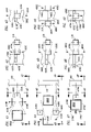
- FIG. 1 presents a perspective view of a portion of one preferred embodiment of a fence system embodying features of the present invention
- FIG. 2 presents a perspective view of one alternative embodiment of the fence of FIG. 1 ;
- FIG. 3 presents a perspective view of a portion of the fence of FIG. 1 ;
- FIG. 4 presents a perspective view of a portion of the fence of FIG. 2 having an offset channel
- FIG. 5 presents a plan cross-sectional view of the portion of the fence of FIG. 1 taken along the line 5 - 5 of FIG. 3 ;
- FIG. 6 presents a cross-sectional elevation view of the fence portion of FIG. 1 taken along the line 6 - 6 of FIG. 5 ;
- FIG. 7 presents a plan view of a union strip embodying features of the present invention for securing wire mesh to a fence system
- FIG. 8 exemplifies an embodiment of a fence portion of FIG. 1 adapted for securing an exterior corner in a fence system embodying features of the present invention
- FIG. 9 presents an elevation view of the fence of FIG. 8 viewed from a back side of FIG. 8 ;
- FIG. 10 exemplifies an alternative embodiment of the fence portion of FIG. 1 adapted for securing an interior corner in a fence system embodying features of the present invention
- FIG. 11 exemplifies one embodiment for coupling rails together in accordance with principles of the present invention.
- FIG. 12 exemplifies an alternative embodiment for coupling rails together in accordance with principles of the present invention.
- FIG. 13 exemplifies an alternative embodiment of a rail having cable extending through it for enhancing the security of a fence system embodying features of the present invention
- FIG. 14 exemplifies one embodiment of a fence system configured as an enclosure having infill material positioned on the exterior of the enclosure and extending across the top of the enclosure in accordance with principles of the present invention
- FIG. 15 exemplifies an alternative embodiment of the present invention wherein rails, union strips, and infill material are positioned on each of two sides of a fence system embodying features of the present invention
- FIG. 16 exemplifies an alternative embodiment of the fence system of FIG. 15 wherein Constantina (also known as concertina) wire is positioned atop a fence system embodying features of the present invention
- FIG. 17 exemplifies a bolt having a carriage head and break-away nut adapted for use in the present invention
- FIG. 18 exemplifies a bolt having a pan head and a break-away nut adapted for use in the present invention
- FIG. 19 presents a partial cross-sectional elevation view of one embodiment of a bolt and breakaway nut for securing a rail to a post of a fence system embodying features of a fence system embodying features of the present invention
- FIG. 20 presents a plan cross-sectional view of one embodiment of a bracket for securing a rail to a post of a fence system embodying features of the present invention
- FIG. 21 exemplifies a plan view of an alternative embodiment of a union strip configured for securing infill material to a fence system embodying features of the present invention
- FIG. 22 exemplifies a plan view of a further alternative embodiment of a union strip configured for securing infill material to a fence system embodying features of the present invention
- FIGS. 23-25 exemplify one plan view and two elevation views, respectively, of a bracket which may be adapted for securing a rail to a post of a fence system embodying features of the present invention
- FIGS. 26-28 exemplify one plan view and two elevation views, respectively, of an alternative bracket which may be adapted for securing a rail to a post of a fence system embodying features of the present invention
- FIGS. 29-31 exemplify one plan view and two elevation views, respectively, of an alternative bracket which may be adapted for securing a rail to a post of a fence system embodying features of the present invention
- FIGS. 32-34 exemplify one plan view and two elevation views, respectively, of an alternative bracket which may be adapted for securing a rail to a post of a fence system embodying features of the present invention
- FIGS. 35-37 exemplify one plan view and two elevation views, respectively, of an alternative bracket which may be adapted for securing a rail to a post of a fence system embodying features of the present invention
- FIGS. 38-40 exemplify one plan view and two elevation views, respectively, of an alternative bracket which may be adapted for securing a rail to a post of a fence system embodying features of the present invention
- FIGS. 41-43 exemplify one plan view and two elevation views, respectively, of an alternative bracket which may be adapted for securing a rail to a post of a fence system embodying features of the present invention
- FIGS. 44-46 exemplify one plan view and two elevation views, respectively, of an alternative bracket which may be adapted for securing a rail to a post of a fence system embodying features of the present invention
- FIGS. 47-49 exemplify one plan view and two elevation views, respectively, of an alternative bracket which may be adapted for securing a rail to a post of a fence system embodying features of the present invention
- FIGS. 50-52 exemplify one plan view and two elevation views, respectively, of an alternative bracket which may be adapted for securing a rail to a post of a fence system embodying features of the present invention
- FIGS. 53-60 exemplify cross-sectional views of various alternative rails that may be utilized in a fence system embodying features of the present invention
- FIGS. 61 and 62 exemplify cross-sectional plan views of the union strip of FIG. 22 secured to a rail by means of fasteners with a cover positioned over the fasteners;
- FIGS. 63 and 64 exemplify cross-sectional plan views of alternative embodiments for securing infill material directly to a rail of a fence system embodying features of the present invention
- FIGS. 65-70 exemplify elevation cross-sectional views of various means for securing union strips to a rail of a fence system embodying features of the present invention
- FIGS. 71-72 exemplify a plan view and a cross-sectional elevation view, respectively, of a bracket which may be adapted for securing infill wire mesh to a rail of a fence system embodying features of the present invention
- FIGS. 73-74 exemplify a plan view and a cross-sectional elevation view, respectively, of an alternative bracket which may be adapted for securing infill wire mesh to a rail of a fence system embodying features of the present invention
- FIGS. 75-76 exemplify a plan view and a cross-sectional elevation view, respectively, of an alternative bracket which may be adapted for securing infill wire mesh to a rail of a fence system embodying features of the present invention
- FIGS. 77-78 exemplify a plan view and a cross-sectional elevation view, respectively, of an alternative bracket which may be adapted for securing infill wire mesh to a rail of a fence system embodying features of the present invention
- FIGS. 79-80 exemplify a plan view and a cross-sectional elevation view, respectively, of an alternative bracket which may be adapted for securing infill wire mesh to a rail of a fence system embodying features of the present invention
- FIGS. 81-82 exemplify a plan view and a cross-sectional elevation view, respectively, of an alternative bracket which may be adapted for securing infill wire mesh to a rail of a fence system embodying features of the present invention
- FIGS. 83-84 exemplify a plan view and a cross-sectional elevation view, respectively, of an alternative bracket which may be adapted for securing infill wire mesh to a rail of a fence system embodying features of the present invention
- FIGS. 85-86 exemplify a plan view and a cross-sectional elevation view, respectively, of an alternative bracket which may be adapted for securing infill wire mesh to a rail of a fence system embodying features of the present invention
- FIGS. 87-88 exemplify a plan view and a cross-sectional elevation view, respectively, of an alternative bracket which may be adapted for securing infill wire mesh to a rail of a fence system embodying features of the present invention
- FIGS. 89-90 exemplify elevation views of two embodiments for mounting a union strip and infill material of a fence system embodying features of the present invention to a wall rather than posts;
- FIGS. 91-94 exemplify elevation views of four embodiments for mounting a rail, union strip, and infill material of a fence system embodying features of the present invention to a wall rather than posts;
- FIGS. 95-96 exemplify side and front elevation views, respectively, of a canted fence system embodying features of the present invention.
- FIG. 97 exemplifies one embodiment for connecting together two rails to form an interior corner of a fence system embodying features of the present invention
- FIG. 98 exemplifies an alternate embodiment for connecting together two rails to form an interior corner of a fence system embodying features of the present invention
- FIG. 99 exemplifies an elevation view of a fence system having pickets in accordance with principles of the present invention
- FIG. 100 depicts a plan view of the picket fence system of FIG. 99 ;
- FIG. 101 depicts a detail portion of the fence system of FIG. 100 ;
- FIG. 102 exemplifies a site plan of a first embodiment of a fence system configured as an enclosure having infill material positioned on the interior of the enclosure and extending across the top of the enclosure in accordance with principles of the present invention
- FIG. 103 presents a plan view of the fence system of FIG. 102 ;
- FIG. 104 presents a bottom view of the fence system of FIG. 102 ;
- FIG. 105 presents an elevation view of the fence system of FIG. 102 taken along the line 105 - 105 of FIG. 102 ;
- FIG. 106 presents an elevation view of the fence system of FIG. 102 taken along the line 106 - 106 of FIG. 102 ;
- FIG. 107 presents an elevation view of the fence system of FIG. 102 taken along the line 107 - 107 of FIG. 102 ;
- FIG. 108 presents an elevation view of the fence system of FIG. 102 taken along the line 108 - 108 of FIG. 102 ;
- FIG. 109 presents an elevation view of the fence system of FIG. 102 taken along the line 109 - 109 of FIG. 102 ;
- FIG. 110 presents an elevation view of the fence system of FIG. 102 taken along the line 110 - 110 of FIG. 102 ;
- FIG. 111 presents an elevation view of the fence system of FIG. 102 taken along the line 111 - 111 of FIG. 102 ;
- FIG. 112 presents an elevation view of the fence system of FIG. 102 taken along the line 112 - 112 of FIG. 102 ;
- FIG. 113 exemplifies an elevation view of a gate adaptable for use with the fence system of FIG. 102 ;
- FIG. 114 exemplifies a site plan of a second embodiment of a fence system configured as an enclosure having infill material positioned on the interior of the enclosure and extending across the top of the enclosure in accordance with principles of the present invention
- FIG. 115 exemplifies a site plan of a third embodiment of a fence system configured as an enclosure having infill material positioned on the interior of the enclosure and extending across the top of the enclosure in accordance with principles of the present invention
- FIG. 116 depicts an elevation view of one preferred embodiment for securing a rafter to a post of an enclosure of FIGS. 102-115 ;
- FIG. 117 depicts an alternate embodiment of the fence system of the present invention wherein union strips are secured horizontally directly to posts;
- FIG. 118 presents an elevation view taken along the line 118 - 118 of FIG. 14 of one preferred embodiment for securing of a rafter to a post of the enclosure of FIG. 14 ;
- FIG. 119 presents an elevation view taken along the line 119 - 119 of FIG. 118 ;
- FIG. 120 presents an elevation view of an alternate embodiment of the present invention adapted for non-horizontal grades.
- the reference numeral 100 generally designates a fence system embodying features of the present invention.
- the fence system 100 preferably includes a number of posts 102 (two of which are shown in FIG. 1 ), which reference numeral 102 generally designates a longitudinal surface thereof as well, and each of which posts define a longitudinal surface 102 ′ and preferably include a conventional cap 104 positioned at the top of each respective post.
- the posts 102 may be of any desired length (e.g., four, eight, or twenty feet), of any desired cross-section (e.g., round, square, elliptical, I-beam, angle iron, and the like), of any desired material (e.g., wood, steel, and the like) and set substantially vertically in cement, a concrete slab, or the like, 103 in any conventional manner as desired.
- at least one substantially horizontal rail 110 is attached to, and defines a longitudinal surface 110 ′ which extends across a portion 102 ′′ ( FIG.
- Infill material 114 is preferably further retained to the rails 110 by clips, exemplified by clips 8102 , such clips being described in further detail below with respect to FIGS. 71-88 .
- the infill material 114 may comprise any material effective for running between union strips 112 , such as, by way of example and not limitation, wire mesh, woven wire mesh, welded wire mesh, expanded metal mesh, perforated panel, steel grate panel, solid sheets of steel, stainless steel, aluminum, plastic, and the like.
- the fence system 100 may comprise four, or any number of, rails 110 , and there is no necessity for the union strips 112 to be aligned with the posts 102 . That the union strips 112 may be aligned or offset from the posts 102 of FIGS. 1 and 2 is further depicted by FIGS. 3 and 4 , respectively.
- Each rail 110 is preferably secured to each of two or more posts 102 via a rail hanger 105 .
- each rail hanger preferably comprises a conventional clamp 106 attached to a post 102 , to which clamp a bracket 108 is attached (e.g., welded).
- the rail 110 is secured to each bracket 108 via conventional fasteners, such as screws, bolts and nuts, and/or the like.
- FIG. 5 is a plan cross-sectional view of the portion of the fence of FIG. 1 taken along the line 5 - 5 of FIG. 3 .
- the rail hanger 105 preferably includes a clamp 106 , and a bolt and nut 107 to tighten the clamp 106 about the post 102 .
- the bracket 108 is preferably welded at a weld joint 113 to the clamp 106 , and the rail 110 is secured to the bracket 108 preferably via four fasteners 109 (two of which are shown in each of FIGS. 3-5 , and two of which are preferably utilized on the opposing side of the bracket 108 , as shown more clearly in FIG.
- the union strip 112 is preferably secured to each rail 110 via at least one fastener 111 such as, by way of example, self-tapping screws, screws with break-away nuts ( FIG. 17 ), rivets, and/or the like.
- FIG. 6 presents a cross-sectional elevation view of the fence portion of FIG. 1 taken along the line 6 - 6 of FIG. 5 .
- the clamp 106 of each rail hanger 105 is vertically offset from its respective bracket 108 , to thereby allow two rail hangers 105 to be complementarily secured to a post 102 for supporting two rails at the same height (e.g., at a corner of a fence), as exemplified and discussed in further detail below with respect to FIGS. 8 and 9 .
- FIG. 7 presents a plan view of the union strip 112 embodying features of the present invention for securing infill material 114 to a fence system embodying features of the present invention.
- the union strip 112 preferably defines two channels 112 a , though the union strip 112 may include but a single channel 112 a where suitable, such as a termination point or corner of a fence.
- a center channel 112 b is preferably formed in the union strip 112 between the channels 112 a
- a hole 112 b ′ is formed in the center channel 112 b for facilitating the passage of a fastener 111 through the hole and to a rail 110 (not shown in FIG. 7 ), to thereby secure the union strip 112 to the rail 110 .
- the center channel 112 b further includes ratchet teeth 112 d and an extended opening portion 112 e .
- a cover strip 702 having projections 702 a and ratchet teeth 702 b is preferably configured for matingly engaging the center channel 112 b and ratchet teeth 112 d , and thereby precluding access to the fasteners 111 and enhancing security of the fence system 100 .
- the union strip 112 preferably also defines a concave radius 112 c opposing the center channel 112 b for providing a spring action effective for enabling a fastener 111 to be securely tightened and, for certain configurations wherein a union strip directly abuts a post 102 , for enabling the union strip 112 to seat against the post 102 .
- FIG. 8 depicts a corner strip 800 adapted for securing an exterior corner of the fence system 100 .
- the corner strip 800 preferably comprises sheet metal fabricated with a 90° bend in it, although the angle of the bend could be any angle suitable for the fence system 100 , and could comprise multiple angles, such as two 45° angles instead of a single 90° angle. While not shown, the corner strip 800 is preferably mounted by passing a fastener, such as a self-tapping screw or the like, the hole 112 b ′ and into the rail 110 securing the corner strip 800 thereto.
- a fastener such as a self-tapping screw or the like
- FIG. 9 presents an elevation view of the portion of the fence system 100 of FIG. 8 viewed from a back side of FIG. 8 .
- the clamps 106 are complementarily positioned relative to each other to permit two rails 110 to be supported at a common height from the same post 102 .
- FIG. 10 depicts an embodiment of a portion of the fence system 100 adapted for securing an interior corner in the fence system. Accordingly, two union strips 112 are preferably positioned on respective rails 110 so that they substantially abut one another, thereby obviating the need for the corner strip 800 discussed above with respect to the external corner depicted in FIG. 8 .
- the rails 110 may be interconnected using any of a number of conventional techniques, such as discussed below with respect to FIGS. 97 and 98 .
- FIGS. 11 and 12 depict two embodiments for coupling co-linear rails 110 together in accordance with principles of the present invention.
- an intermediate coupler 1102 is configured for fitting within the ends of two rails 110 to connect together the two rails.
- One or more holes 1104 are formed in each of the rails 110 to be coupled, so that when the rails 110 receive the coupler 1102 , a fastener 1106 , such as a self-tapping screw, or the like, may be extended through each hole 1104 , and into the intermediate coupler 1102 to thereby secure together the two rails 110 via the coupler 1102 .
- a fastener 1106 such as a self-tapping screw, or the like
- one rail 110 designated by the reference numeral 1200 , is swaged at one end 1202 to fit within a corresponding rail 110 , and one or more holes 1204 are defined in the rail 110 , through each of which holes 1204 a fastener 1204 , such as a self-tapping screw, or the like, is extended into the swaged end 1202 of the rail 1200 to secure together the two rails 110 and 1200 .
- a fastener 1204 such as a self-tapping screw, or the like
- FIG. 13 presents a rail 110 having a cable 1300 extending through it for enhancing the security of the fence system 100 .
- the cable 1300 is preferably secured at each end of the rail 110 to a relatively immovable object, such as a monument, anchor in the ground, or the like.
- FIG. 14 exemplifies an embodiment of the present invention having infill material extending across the top of the fence system, to thereby form an enclosure 1400 , such as a tool bin in a retail store.
- the rafters 1402 extend between the tops of posts 102
- rails 110 extend across the rafters 1402
- union strips 112 extend across the rails 110 .
- Infill material 114 is then positioned in, and retained by, the channels 112 a of the union strips 112 , and further retained to the rails via clips, such as the clips 8102 , to secure the top of the enclosure 1400 .
- FIGS. 118 and 119 there is depicted one preferred embodiment for securing a rafter 1402 to a post 102 .
- the rafter 1402 is preferably positioned on top of the post 102 , and is secured thereto by two plates 10902 (only one of which is shown in FIG. 118 ) fastened to both the rafter 1402 and the post 102 via conventional fasteners, such as the bolt 1702 or 1802 and nut 1704 , described in further detail below with respect to FIGS. 17 and 18 .
- Rails 110 are secured to the post 102 and rafter 1402 via rail hangers, such as the rail hangers 105 described above with respect to FIGS. 3-5 .
- union channels 112 are secured to the rails 110 , and infill material 114 is positioned in, and retained by, the union channels 112 , and further retained to the rails via clips, such as the clips 8102 .
- FIG. 15 presents an alternative embodiment 1500 of the present invention wherein rails 110 , union strips 112 , and infill material 114 , such as wire mesh, is secured to two sides of a fence system, to thereby provide additional security. It may be appreciated that the rails 110 , union strips 112 , and wire mesh 114 may be different on each side, as desired.
- FIG. 16 presents an alternative embodiment 1600 of the present invention wherein barbed wire, such as Constantina (also known as concertina) wire (i.e., barbed wire that is extended in a spiral for use as a barrier), is positioned atop the fence system of FIG. 15 , to thereby provide still further security.
- barbed wire such as Constantina (also known as concertina) wire (i.e., barbed wire that is extended in a spiral for use as a barrier)
- FIG. 17 depicts a bolt (or screw) 1700 preferably having a carriage type of head 1702 (i.e., a “dome-shaped” head with no driver slot) and square shoulder 1703 , and configured for receiving a nut 1704 , adapted for use in the present invention.
- the nut 1704 preferably comprises a main portion 1704 a having a conical type head, and a breakaway portion 1704 b configured for breaking away from the main portion 1704 a upon the application of a predetermined amount of torque, thereby rendering the main portion 1704 a on the bolt 1700 not readily removable, thereby enhancing security still further.
- FIG. 18 depicts a bolt (or screw) 1800 similar to the bolt (or screw) 1700 , but for having a pan type of head 1802 (i.e., a head with a driver slot, such as a Phillips head, a square head, or the like), no square shoulder 1703 , and configured for receiving the breakaway nut 1704 , for use in the present invention.
- a pan type of head 1802 i.e., a head with a driver slot, such as a Phillips head, a square head, or the like
- no square shoulder 1703 i.e., a head with a driver slot, such as a Phillips head, a square head, or the like
- FIG. 19 presents a cross-sectional elevation view of an alternative embodiment of a rail hanger for securing a rail 110 to a post 102 of the fence system of FIG. 1 , wherein a bracket 1900 wraps around the rail 110 .
- bolts 1702 are extended through the bracket 1900 and post 102 , and then secured thereto via a nut, such as the nut 1704 described above with respect to FIG. 17 , to thereby secure the bracket 1900 and rail 110 to the post 102 .
- FIG. 20 presents a plan, partial cross-sectional view of an alternative embodiment of a rail hanger for securing a rail 110 to a post 102 of the fence system 100 , wherein a rail hanger bracket 2000 wraps around the post 102 .
- bolts (or screws) 1702 extend from the rail 110 into the bracket 2000 and are secured thereto via a nut, such as the nut 1704 , described above with respect to FIG. 17 , to thereby secure the rail to the post 102 .
- FIG. 21 presents a plan view of alternative means for securing infill material 114 to a rail 110 of the fence system 100 .
- a first shaped bar, or strip, 2102 extending perpendicularly into the figure, as viewed in FIG. 21 , is positioned against the rail 110
- a second shaped bar, or strip, 2104 similar to the first strip 2102 is positioned to abut the first strip 2102 and form channels similar to the channels 112 a
- the strips 2102 and 2104 are secured to the rail 110 via a fastener, such as the bolt 1702 and nut 1704 , a conventional screw, bolt, or the like, extended through holes suitably defined in the strips 2102 and 2104 .
- Infill material 114 is sandwiched in the channels formed between the strips 2100 and 2102 .
- the strips 2102 and 2104 are preferably fabricated from metal, such as steel or aluminum, or from a plastic, fiberglass, or the like, effective for securing the infill material 114 to the rails 110 .
- FIG. 22 depicts an alternative embodiment 2200 of the fence system 100 similar to the embodiment described above with respect to FIG. 21 , but for incorporating a flat bar, or strip, 2202 in place of the shaped strip 2102 .
- the strips 2202 and 2104 are positioned to abut one against the other and form channels similar to the channels 112 a into which infill material 114 is positioned.
- FIGS. 23-52 exemplify additional alternative embodiments that may be implemented for mounting a rail 110 to a post 102 in accordance with principles of the present invention.
- FIGS. 23-25 depict one plan view and two elevation views, respectively, of one embodiment of a rail hanger 2300 adapted for mounting a rail 110 to a post 102 via a bracket 2300 .
- two or more fasteners 2400 such as self-tapping screws, rivets, or the like, are preferably utilized to secure the bracket 2300 directly to the post 102
- two or more fasteners 2402 are preferably utilized to secure the rail 110 to the bracket 2300 .
- two opposing fasteners 2402 may be replaced by a single longer fastener, such as the bolt 1702 and nut 1704 described above with respect to FIG. 17 .
- FIGS. 26-28 depict one plan view and two elevation views, respectively, of one embodiment of a rail hanger 2600 adapted for mounting a rail 110 to a post 102 .
- the rail hanger 2600 comprises a clamp 2602 and a bracket 2604 secured (e.g., welded) to the clamp 2602 .
- the clamp 2602 includes a fastener, such as a bolt 1702 and nut 1704 to secure the clamp to the post 102 .
- two or more fasteners 2702 are preferably utilized to secure the rail 110 to the bracket 2604 . It will be appreciated that two opposing fasteners 2702 may be replaced by a single longer fastener, such as the bolt 1702 and nut 1704 described above with respect to FIG. 17 .
- FIGS. 29-31 depict one plan view and two elevation views, respectively, of one embodiment of a rail hanger 2900 adapted for mounting a rail 110 to a post 102 .
- the rail hanger 2900 comprises a semi-circular wrap 2902 and two brackets 2904 secured (e.g., welded) to the wrap 2902 .
- two or more fasteners 2906 such as self-tapping screws, rivets, or the like, are provided for securing the wrap 2902 to the post 102 .
- four or more fasteners 3002 are provided for securing the wrap 2902 to the post 102 .
- FIGS. 32-34 depict one plan view and two elevation views, respectively, of one embodiment of a rail hanger 3200 adapted for mounting a rail 110 to a post 102 .
- the rail hanger 3200 comprises a semi-circular wrap 3202 and a bracket 3204 secured (e.g., welded) to the wrap 3202 .
- two or more fasteners 3206 such as-self-tapping screws, rivets, or the like, are provided for securing the wrap 3202 to the post 102 .
- at least two fasteners 3302 are preferably utilized to secure the rail 110 to the bracket 3204 .
- two opposing fasteners 3206 or 3302 may be replaced by a single longer fastener, such as the bolt 1702 and nut 1704 described above with respect to FIG. 17 .
- FIGS. 35-37 depict one plan view and two elevation views, respectively, of one embodiment of a rail hanger 3500 , similar to the rail hanger described above with respect to FIG. 20 , adapted for mounting a rail 110 to a post 102 .
- the rail hanger 3500 comprises a semi-circular wrap 3502 and two ears 3504 formed and extending from the wrap 3502 .
- two or more fasteners 3506 are provided for securing the rail hanger 3500 via the ears 3504 to the rail 110 , and thus the rail to the post 102 .
- one or more fasteners may optionally be provided for further securing the rail hanger 3500 to the post 102 .
- FIGS. 38-40 depict one plan view and two elevation views, respectively, of one embodiment of a rail hanger 3800 adapted for mounting a rail 110 to a square post 3802 , in a manner similar to that depicted in FIGS. 35-37 , but for the post 3802 having a square cross-section.
- the rail hanger 3800 comprises a semi-square wrap 3803 and two ears 3804 formed and extending from the wrap 3803 .
- two or more fasteners 3806 such as self-tapping screws, rivets, or the like, are provided for securing the rail hanger 3800 via the ears 3504 to the rail 110 , and thus the rail 110 to the post 3802 .
- one or more fasteners may optionally be provided for further securing the rail hanger 3800 to the post 3802 .
- FIGS. 41-43 depict one plan view and two elevation views, respectively, of one embodiment of a rail hanger 4100 adapted for mounting a rail 110 to the square post 3802 , in a manner similar to that depicted in FIGS. 32-34 , but for the post 3802 having a square cross-section.
- the rail hanger 4100 comprises a semi-square wrap 4102 and a bracket 4104 secured (e.g., welded) to the wrap 4102 .
- two or more fasteners 4106 such as self-tapping screws, rivets, or the like, are provided for securing the wrap 4102 to the post 3802 .
- FIGS. 41-43 depict one plan view and two elevation views, respectively, of one embodiment of a rail hanger 4100 adapted for mounting a rail 110 to the square post 3802 , in a manner similar to that depicted in FIGS. 32-34 , but for the post 3802 having a square cross-section.
- the rail hanger 4100 comprises a semi-square wrap
- At least two fasteners 4202 are preferably utilized to secure the rail 110 to the bracket 4104 . It will be appreciated that two opposing fasteners 4106 or 4202 may be replaced by a single longer fastener, such as the bolt 1702 and nut 1704 described above with respect to FIG. 17 .
- FIGS. 44-46 depict one plan view and two elevation views, respectively, of one embodiment of a rail hanger 4400 adapted for mounting a rail 110 to the square post 3802 , in a manner similar to that depicted in FIGS. 29-31 , but for the post 3802 having a square cross-section.
- the rail hanger 4400 comprises a semi-square wrap 4402 and two brackets 4404 secured (e.g., welded) to the wrap 4402 .
- two or more fasteners 4406 such as self-tapping screws, rivets, or the like, are provided for securing the wrap 4402 to the post 3802 .
- FIGS. 44-46 depict one plan view and two elevation views, respectively, of one embodiment of a rail hanger 4400 adapted for mounting a rail 110 to the square post 3802 , in a manner similar to that depicted in FIGS. 29-31 , but for the post 3802 having a square cross-section.
- the rail hanger 4400 comprises a semi-square wrap
- fasteners 4502 are utilized to secure the rail 110 to the bracket 4404 .
- fasteners 4406 or 4502 may be replaced by a single longer fastener, such as the bolt 1702 and nut 1704 described above with respect to FIG. 17 .
- FIGS. 47-49 depict one plan view and two elevation views, respectively, of one embodiment of a rail hanger 4700 adapted for mounting a rail 110 to the square post 3802 , in a manner similar to that depicted in FIGS. 26-28 , but for the post 3802 having a square cross-section.
- the rail hanger 4700 comprises a clamp 4702 and a bracket 4704 secured (e.g., welded) to the clamp 4702 .
- the clamp 4702 includes a fastener, such as a bolt 1702 and nut 1704 to secure the clamp to the post 3802 .
- two or more fasteners 4802 are preferably utilized to secure the rail 110 to the bracket 4704 .
- two opposing fasteners 4802 may be replaced by a single longer fastener, such as the bolt 1702 and nut 1704 described above with respect to FIG. 17 .
- FIGS. 50-52 depict one plan view and two elevation views, respectively, of one embodiment of a rail hanger 5000 adapted for mounting a rail 110 to the square post 3802 , in a manner similar to that depicted in FIGS. 23-25 , but for the post 3802 having a square cross-section.
- two or more fasteners 5100 such as self-tapping screws, rivets, or the like, are preferably utilized to secure the bracket 5000 directly to the post 3802
- two or more fasteners 5102 are preferably utilized to secure the rail 110 to the bracket 5000 .
- two opposing fasteners 5102 may be replaced by a single longer fastener, such as the bolt 1702 and nut 1704 described above with respect to FIG. 17 .
- FIGS. 53-60 exemplify selected cross-sectional views of various rails that may be utilized with the present invention. More specifically, FIG. 53 depicts a cross-section of a rail 5300 , configured using a Unistrut® metal frame, having a channel structure 5302 defining a channel opening 5304 , and fabricated from a material such as metal.
- the structure 5302 includes edges 5306 turned inwardly and defining the channel opening 5304 .
- a channel nut 5308 is positioned within the interior of the structure 5302 , abutting the edges 5306 .
- Use of the rail 5300 is described in further detail below with respect to FIG. 65 .
- FIG. 54 depicts a rail 5400 configured in the shape of a structural channel.
- FIG. 55 depicts a rail 5500 configured as square tubing.
- FIGS. 56 and 57 depict rails 5600 and 5700 configured in the shape of a substantially rectangular tubing, each rail being oriented 90° from the other.
- FIG. 58 depicts a rail 5800 configured in the shape of around tube or pipe.
- FIGS. 59 and 60 respectively depict a rail 5900 configured in the shape of a conventional I-beam, and a rail 6000 configured in the shape of a wide-flange I-beam.
- the rails presented herein are presented by of example, and not limitation, and rails utilized may assume any of a number of other configurations, such as, elliptical, angle iron, and the like.
- FIG. 61 depicts a plan view of an embodiment of a channel structure which is similar to the embodiment described above with respect to FIG. 22 , but for further including the cover strip 702 , and modifying the shaped strip 2104 to receive the cover strip 702 . More specifically, as described above with respect to FIG. 22 , the flat strip 2202 is positioned against the rail 110 , and infill material 114 is sandwiched between the flat strip 2202 and the shaped strip 2104 . The shaped strip 2104 is modified as described above with respect to FIG. 7 to define a center channel 112 b with ratchet teeth 112 d for matingly receiving the cover strip 702 . Because the center channel 112 b and cover strip 702 were described in some detail above with respect to FIG. 7 , they will not be described in further detail herein.
- FIG. 62 is similar to FIG. 61 , but for using a fastener 6202 , such as a self-tapping screw, a rivet, or the like, in place of the bolt 1702 and nut 1704 .
- a fastener 6202 such as a self-tapping screw, a rivet, or the like
- FIGS. 63 and 64 depict alternate embodiments of the channel structures described above with respect to FIGS. 61 and 62 , respectively, but for replacing the shaped strip 2104 with a second flat strip 2202 , and as a consequence, foregoing use of the cover strip 702 .
- FIGS. 65-70 are elevation views which exemplify, without limitation, a number of alternate embodiments for mounting, in accordance with principles of the present invention, a channel or flat bar for containing and retaining infill material to a rail.
- a union strip 112 is positioned for being mounted on the Unistrut® channel rail 5300 described in further detail above with respect to FIG. 53 .
- the union strip 112 is mounted to the rail 5300 by passing a fastener 6502 , such as a screwor the like, through the hole 112 b ′ of the union strip 112 into the channel nut 5308 and tightening the fastener 6502 .
- a fastener 6502 such as a screwor the like
- two angle brackets 6602 are mounted to the rail 110 via fasteners, such as screws, 6604 .
- the union strip 112 is mounted to the brackets 6602 , and hence to the rail 110 , via fasteners, such as a bolt 1702 and nut 1704 , described in further detail above with respect to FIG. 17 .
- a bracket 6702 is configured to wrap the rail 110 , and includes one ear 6702 a .
- the union strip 112 is mounted to the ear 6702 a of the bracket 6702 , and hence to the rail 110 , via fasteners, such as a bolt 1702 and nut 1704 , described in further detail above with respect to FIG. 17 .
- a bracket 6802 is configured to be wrap the rail 110 , and includes two ears 6802 a .
- the union strip 112 is mounted to the two ears 6802 a of the bracket 6802 , and hence to the rail 110 , via fasteners, such as a bolt 1702 and nut 1704 , described in further detail above with respect to FIG. 17 .
- the union strip 112 is mounted directly to the rail 110 via fasteners, such as a bolt 1702 and nut 1704 , described in further detail above with respect to FIG. 17 .
- the union strip 112 is mounted directly to the rail 110 via a fastener 7002 , such as a self-tapping screw, a rivet, or the like.
- FIGS. 71-88 exemplify, without limitation, a number of alternate embodiments of clips for preferably further securing, in accordance with principles of the present invention, infill material 114 directly to a rail 110 , 1200 , 5300 , or the like, intermediate to the channel strips 112 .
- a bracket 7102 is positioned over a portion (e.g., a wire) of infill material 114 .
- Fasteners 7104 such as self-tapping screws, rivets, or the like, are provided for securing each end of the bracket 7102 to the rail 110 , thereby securing the infill material 114 to the rail 110 .
- a bracket 7302 is positioned over a portion (e.g., a wire) of infill material 114 .
- a fastener 7304 such as a self-tapping screw, a rivet, or the like, is provided for securing one end of the bracket 7302 to the rail 110 , thereby securing the infill material 114 to the rail 110 .
- a bracket 7502 is positioned over a portion (e.g., two wires) of infill material 114 .
- a fastener 7504 such as a self-tapping screw, a rivet, or the like, is provided for securing a central portion of the bracket 7502 to a Unistrut® rail 5300 , thereby securing the infill material 114 to the rail 5300 .
- an angle bracket 7706 is mounted on the rail 110 in any conventional manner, using, by way of example, one or more fasteners 7708 (e.g., a self-tapping screw or rivet).
- a bracket 7702 is positioned over a portion (e.g., two wires) of infill material 114 .
- a fastener such as a bolt 1702 and nut 1704 described above with respect to FIG. 17 , is provided for securing a central portion of the bracket 7702 to the angle bracket 7706 , thereby securing the infill material 114 to the rail 110 .
- a channel-shaped bracket 7904 having an ear 7904 a is configured for fitting on the rail 110 .
- a bracket 7902 is positioned over a portion (e.g., two wires) of infill material 114 .
- a fastener such as a bolt 1702 and nut 1704 described above with respect to FIG. 17 , is provided for securing a central portion of the bracket 7902 to the ear 7904 a of the bracket 7904 , thereby securing the infill material 114 to the rail 110 .
- a channel-shaped bracket 8102 is sized for fitting on the rail 110 .
- the bracket 8102 is positioned over a portion (e.g., one or two wires) of infill material 114 , and then fitted over the rail 110 .
- Two or more fasteners such as self-tapping screws, rivets, or the like, are provided for securing the bracket 8102 , and hence the infill material 114 , to the rail 110 .
- a bracket 8302 is positioned over a portion (e.g., two wires) of infill material 114 .
- a fastener such as a bolt 1702 and nut 1704 described above with respect to FIG. 17 , is provided for securing a central portion of the bracket 8302 to the rail 110 , thereby securing the infill material 114 to the rail 110 .
- a channel-shaped bracket 8504 having two ears 8504 a is configured for fitting on the rail 110 .
- Two brackets 8502 are positioned over a portion (e.g., two wires each) of infill material 114 .
- a fastener such as a bolt 1702 and nut 1704 described above with respect to FIG. 17 , is provided for securing a central portion of each bracket 8502 to the ear 8504 a of the bracket 8504 , thereby securing the infill material 114 to the rail 110 .
- a bracket 8702 is positioned over a portion (e.g., two wires) of infill material 114 .
- a fastener 8704 such as a self-tapping screw, a rivet, or the like, is provided for securing a central portion of the bracket 8702 to the rail 110 , thereby securing the infill material 114 to the rail 110 .
- FIGS. 89-90 are elevation views which exemplify, without limitation, two alternate embodiments for mounting union strips 112 , without rails, to a wall 8902 , such as a concrete wall, a mortar wall, brick wall, or the like, rather than posts, in accordance with principles of the present invention.
- a carriage head bolt 1702 is extended through a hole 112 b ′ of a union strip 112 and through the wall 8902 and tightened onto a breakaway nut 1704 , preferably with a washer 8904 positioned between the wall 8902 and the nut 1704 .
- a fastener 9002 such as a self-tapping screw, a rivet, or the like, is extended through a hole 112 b ′ of a union strip 112 and threaded or secured in the wall 8902 .
- the union strips 112 may be secured to the wall 8902 with a suitable adhesive, or adhesive may be used in conjunction with the embodiment depicted by FIGS. 89 or 90 above.
- FIGS. 91-94 are elevation views which exemplify, without limitation, four alternate embodiments for mounting rails 110 to the wall 8902 described above, in accordance with principles of the present invention.
- a rail 110 is secured to the wall 8902 using any suitable adhesive 9102 effective for adhering the rail to the wall, e.g., for adhering metal to concrete.
- the union strip 112 is secured to the rail 110 via one or more fasteners 9100 , such as self-tapping screws, rivets, or the like.
- the union strip 112 may be secured to the rail 110 using any of a number of different techniques, such as exemplified in FIGS. 65-70 described above.
- a Unistrut® rail 5300 is secured to the wall via one or more fasteners 9202 , such as, for example, self-tapping screws, or the like.
- a union strip 112 is secured to the rail 5300 via a fastener 9204 as described above with respect to FIG. 65 .
- brackets 9300 are positioned above and below the rail 110 and secured thereto with one or more fasteners 9304 , such as, for example, self-tapping screws, rivets, or the like.
- the brackets 9300 are then secured to the wall 8902 via one or more fasteners 9302 , such as, for example, self-tapping screws, or the like.
- the union strip 112 is secured to the rail 110 via one or more fasteners 9306 , such as self-tapping screws, rivets, or the like.
- the union strip 112 may be secured to the rail 110 using any of a number of different techniques, such as exemplified in FIGS. 65-70 described above.
- a channel-shaped bracket 9400 having upper and lower ears 9400 a is sized for fitting about the rail 110 .
- Two or more fasteners such as self-tapping screws, or the like, are provided for securing the ears 9400 a of the bracket 9400 , and hence the rail 110 , to the wall 8902 .
- the union strip 112 is secured to the rail 110 via one or more fasteners 9404 , such as self-tapping screws, rivets, or the like.
- the union strip 112 may be secured to the rail 110 using any of a number of different techniques, such as exemplified in FIGS. 65-70 described above.
- FIGS. 95 and 96 exemplify side and frontal elevation views, respectfully, of a canted fence system 9500 embodying features of the present invention.
- the fence system 9500 includes a vertical portion 9502 and a canted portion 9504 .
- the vertical portion 9502 is substantially similar to the embodiments of the fence system 100 described above with respect to FIGS. 1-94
- the canted portion 9504 is substantially similar to the vertical portion 9502 , but for being canted at an angle 9506 , such as 45°, though the angle may vary as desired between 1° and 90°.
- the post 102 is canted at the vertex 9508 in any conventional manner; for example, two straight posts may be welded together, or connected together via a post bend connected to each post, or an extended post 102 may be bent at the vertex 9508 .
- two union strips 9612 similar to the union strips 112 , are preferably positioned to abut one another and receive the vertical and canted portions of infill material 114 .
- the infill material may be bent at the vertex, or a corner strip, similar to the corner strip 800 ( FIG. 8 ) may be positioned at the vertex.
- the rails 110 and union strips 112 are mounted to the posts 102 as described above with respect to FIGS. 1-94 .
- one or more additional canted portions may be extended from the canted portion 9504 .
- the canted portion 9504 may be curvilinear, and/or an additional canted portion 9504 may be mirrored, to thereby form a “Y”, as viewed in FIG. 95 .
- barbed wire or Constantina wire may be positioned atop the fence system 9500 , as discussed above with respect to FIG. 16 .
- FIG. 97 is a plan view which exemplifies one embodiment for conjoining together a first rail 110 a to a second rail 110 b at a corner of a fence system embodying features of the present invention, similarly as discussed above with respect to FIG. 10 .
- a channel-shaped bracket 9702 is positioned proximate to an end 110 a ′ of the first rail 110 a , and a fastener, such as a self-tapping screw 9704 , is then extended through a hole (not shown) formed in the bracket 9702 and into the end 110 a ′ of the first rail 110 a to secure the bracket 9702 to the rail 110 a .
- the end 110 b ′ of the second rail 110 b is then secured to the bracket 9702 in any conventional manner, such as by fasteners, such as a self-tapping screw, bolt, or the like, or via welding, or the like.
- fasteners such as a self-tapping screw, bolt, or the like, or via welding, or the like.
- union strips 112 positioned on the interior of the fence corner preferably abut one another to maximize the security of the fence system.
- FIG. 98 is a plan view which exemplifies an alternate embodiment for conjoining together a first rail 110 a to a second rail 110 b at a corner of a fence system, similarly as discussed above with respect to FIG. 97 , but for using a fastener 9804 , such as a bolt 1702 and nut 1704 , which extends through the entire rail 110 a.
- a fastener 9804 such as a bolt 1702 and nut 1704 , which extends through the entire rail 110 a.
- FIGS. 99-101 exemplify one embodiment providing for pickets on a picket fence system 9900 in accordance with principles of the present invention, as may be desired by retail garden centers for not only enhancing security, but also providing a degree of ornamentation.
- a picket fence system 9900 preferably two or more flat plates 9904 are positioned horizontally between two union strips 112 across infill material 114 , and pickets 9902 are mounted (e.g., welded) on the flat plates 9904 .
- FIG. 100 taken along the line 100 - 100 of FIG. 99 , shows a plan view of the picket fence 9900 .
- FIG. 101 depicts detail of a portion of the picket fence 9900 within the line 101 of FIG. 100 . More specifically, as shown in FIG. 101 , both the infill material 114 and the flat plates 9904 are positioned and secured within the channels 112 a of the union strip 112 .
- FIGS. 102-114 exemplify various views of an enclosure 10200 configured in accordance with principles of the present invention, for preventing persons on the inside from getting out, as in an exercise pen in a correctional institution.
- a site plan view is shown of an overall structure for the enclosure 10200 .
- the enclosure 10200 defines a structure having twelve posts 102 and four rafters 10202 (shown in dashed outline) extending between eight of the posts 102 , though more or less posts and rafters may be utilized as suitable or desirable.
- Three rails 110 (shown in dashed outline, it being understood that more or less rails may be utilized as desired), extend perpendicularly across the rafters 10202 . As shown more clearly in FIGS.
- union strips 112 extend perpendicularly across the rails 110 .
- Infill material 114 and a solid sheet of material (e.g., aluminum or the like) 10302 extends between, and is retained by, union strips 112 , and is preferably further retained to the rails 110 by clips, such as clips 8102 , to thereby secure the top of the enclosure 10200 .
- FIGS. 105 and 106 depict one side of the enclosure 10200 , viewed from the exterior and interior sides of the enclosure, respectively. As shown therein, the enclosure 10200 is preferably provided with a gate 10502 , discussed in further detail below with respect to FIG. 113 . It is noted that posts 102 extend below the lower edge of the infill material 114 for being embedded in ground or a concrete slab.
- FIGS. 107 and 108 depict a side of the enclosure 10200 opposite the side depicted in FIGS. 105 and 106 , viewed from the exterior and interior sides of the enclosure, respectively.
- FIGS. 109 and 110 depict one end of the enclosure 10200 , viewed from the exterior and interior sides of the enclosure, respectively.
- rafters 10202 are preferably mounted and secured to posts 102 via a rafter-post plate 10902 , discussed below in further detail with respect to FIG. 116 .
- FIGS. 111 and 112 depict an end of the enclosure 10200 opposite the side depicted in FIGS. 109 and 110 , viewed from the exterior and interior sides of the enclosure, respectively.
- FIG. 113 exemplifies, without limitation, details of the structure of the gate 10502 used in conjunction with the enclosure 10200 , as described above with respect to FIGS. 105-106 .
- the gate 10502 is sized and configured as needed in a conventional manner. More specifically, the gate 10502 comprises vertical structural members 11302 connected together via horizontal structural members 11304 in a conventional manner.
- Union strips 112 are preferably positioned on the vertical members 11302 , and, as described above, infill material 114 is positioned within channels 112 a of the union strips 112 , and further secured thereto via a suitable clamp, such as described above with respect to FIGS. 71-88 , exemplified as bracket 7102 , positioned on a horizontal member 11304 intermediate the union strips 112 .
- FIGS. 114 and 115 depict two site plans, alternative to the site plan depicted in FIG. 102 , which exemplify alternative embodiments of enclosure 10200 which may be configured in accordance with principles of the present invention. More specifically, FIGS. 114 and 115 exemplify, respectively, how fewer or additional rafters 10202 and posts 102 (not all of which are shown) may be utilized with and distributed about the enclosure.
- FIG. 116 exemplifies one preferred embodiment of a rafter-post plate 10902 that may be utilized to secure a rafter 10202 to a post 102 .
- the plate 10902 is preferably a conventional flat plate attached via conventional fasteners (e.g., bolts and nuts) to each respective rafter 10202 and post 102 .
- fasteners e.g., bolts and nuts
- rails 110 , channels 112 , and infill material 114 are secured to the post 102 and rafter 10202 as described above with respect to FIGS. 1-101 .
- a high security fence may be erected, or retrofitted onto posts of a previous fence, using standard sheeted infill material secured to posts that are spaced apart at non-standard intervals, or attached to a wall.
- the posts furthermore, may be round or square, and of virtually any size, as depicted in FIGS. 53-60 .
- sheeted infill material does not require fabrication of a frame for the mesh panels and, therefore, no post-fabrication galvanization, is required.
- the union strips 112 contain rough cutting edges that may exist with infill material 114 .
- the fence of the present invention may also be aesthetically appealing.
- FIG. 117 A further example is depicted by FIG. 117 wherein in a fence system 11700 , union strips 112 are attached horizontally and directly to the posts 102 using channel hangers 11705 substantially similar to the rail hangers 105 ( FIGS. 3-5 , 19 , and 23 - 52 ), but adapted for supporting horizontal union strips 112 without using rails 110 . Further to FIG. 117 , vertically oriented unions strips 112 may optionally be utilized to join or terminate vertical edges of infill material 114 .
- infill material 12014 such as woven wire mesh
- infill material 12014 may be utilized having non-vertical wires that may be canted at an angular deviation 12002 from a horizontal plane 12004 , while permitting the vertical wires remain substantially vertical, to thereby facilitate implementation of the fence system of the present invention on a graded surface 12003 , corresponding to the substantially horizontal surface 103 discussed above with respect to FIGS. 1 and 2 .
Landscapes
- Engineering & Computer Science (AREA)
- Architecture (AREA)
- Civil Engineering (AREA)
- Structural Engineering (AREA)
- Fencing (AREA)
- Tents Or Canopies (AREA)
- Refuge Islands, Traffic Blockers, Or Guard Fence (AREA)
- Management, Administration, Business Operations System, And Electronic Commerce (AREA)
- Road Signs Or Road Markings (AREA)
Priority Applications (15)
| Application Number | Priority Date | Filing Date | Title |
|---|---|---|---|
| US11/110,579 US7628386B2 (en) | 2005-01-07 | 2005-04-19 | Fence system |
| MX2007008316A MX2007008316A (es) | 2005-01-07 | 2006-01-09 | Sistema de cercado. |
| BRPI0606470-1A BRPI0606470A2 (pt) | 2005-01-07 | 2006-01-09 | sistema de cerca incluindo pelo menos dois pilares e método para montar o mesmo |
| CA2593795A CA2593795C (en) | 2005-01-07 | 2006-01-09 | Fence system |
| EP06717847A EP1841551A2 (en) | 2005-01-07 | 2006-01-09 | Fence system |
| AU2006203840A AU2006203840B2 (en) | 2005-01-07 | 2006-01-09 | Fence system |
| PCT/US2006/000694 WO2006074440A2 (en) | 2005-01-07 | 2006-01-09 | Fence system |
| MX2010007409A MX352156B (es) | 2005-01-07 | 2006-01-09 | Sistema de cercado. |
| US11/669,601 US8910925B2 (en) | 2005-01-07 | 2007-01-31 | Fence enclosure system |
| IL184422A IL184422A0 (en) | 2005-01-07 | 2007-07-05 | Fence system |
| US12/024,102 US7866635B2 (en) | 2005-01-07 | 2008-01-31 | Fence system |
| US12/632,693 US9435136B2 (en) | 2005-01-07 | 2009-12-07 | Fence system |
| US12/969,785 US8783661B1 (en) | 2005-01-07 | 2010-12-16 | Fence system |
| US14/338,267 US9428934B1 (en) | 2005-01-07 | 2014-07-22 | Fence system |
| US15/252,136 US10006221B1 (en) | 2005-01-07 | 2016-08-30 | Fence system |
Applications Claiming Priority (2)
| Application Number | Priority Date | Filing Date | Title |
|---|---|---|---|
| US64207905P | 2005-01-07 | 2005-01-07 | |
| US11/110,579 US7628386B2 (en) | 2005-01-07 | 2005-04-19 | Fence system |
Related Child Applications (2)
| Application Number | Title | Priority Date | Filing Date |
|---|---|---|---|
| US11/669,601 Continuation-In-Part US8910925B2 (en) | 2005-01-07 | 2007-01-31 | Fence enclosure system |
| US12/632,693 Continuation US9435136B2 (en) | 2005-01-07 | 2009-12-07 | Fence system |
Publications (2)
| Publication Number | Publication Date |
|---|---|
| US20060151770A1 US20060151770A1 (en) | 2006-07-13 |
| US7628386B2 true US7628386B2 (en) | 2009-12-08 |
Family
ID=36648245
Family Applications (2)
| Application Number | Title | Priority Date | Filing Date |
|---|---|---|---|
| US11/110,579 Expired - Lifetime US7628386B2 (en) | 2005-01-07 | 2005-04-19 | Fence system |
| US12/632,693 Expired - Lifetime US9435136B2 (en) | 2005-01-07 | 2009-12-07 | Fence system |
Family Applications After (1)
| Application Number | Title | Priority Date | Filing Date |
|---|---|---|---|
| US12/632,693 Expired - Lifetime US9435136B2 (en) | 2005-01-07 | 2009-12-07 | Fence system |
Country Status (8)
| Country | Link |
|---|---|
| US (2) | US7628386B2 (pt) |
| EP (1) | EP1841551A2 (pt) |
| AU (1) | AU2006203840B2 (pt) |
| BR (1) | BRPI0606470A2 (pt) |
| CA (1) | CA2593795C (pt) |
| IL (1) | IL184422A0 (pt) |
| MX (2) | MX2007008316A (pt) |
| WO (1) | WO2006074440A2 (pt) |
Cited By (6)
| Publication number | Priority date | Publication date | Assignee | Title |
|---|---|---|---|---|
| US20080185565A1 (en) * | 2007-02-06 | 2008-08-07 | C.E. Shepherd Co., Inc. | Fence and installation method therefor |
| US20090321701A1 (en) * | 2008-06-30 | 2009-12-31 | Payne Fence Products, Llc | Fence System |
| US20100078613A1 (en) * | 2005-01-07 | 2010-04-01 | Payne Fence Products, Llc | Fence System |
| US20130139461A1 (en) * | 2011-12-05 | 2013-06-06 | Troax AB | Attachment of wall elements |
| US11408196B2 (en) * | 2019-05-29 | 2022-08-09 | Melanie Jo Cogburn | Channeled fence post for building horizontal fence, method of creating horizontal fence and method for manufacture of fence post |
| US11891831B1 (en) * | 2018-07-17 | 2024-02-06 | Ameristar Perimeter Security Usa Inc. | Infill-covered barrier |
Families Citing this family (31)
| Publication number | Priority date | Publication date | Assignee | Title |
|---|---|---|---|---|
| US7775526B1 (en) | 2001-12-12 | 2010-08-17 | Action Target Inc. | Bullet trap |
| US7789666B2 (en) * | 2004-12-30 | 2010-09-07 | Action Target Inc. | Training door |
| US8910925B2 (en) * | 2005-01-07 | 2014-12-16 | Betafence Usa Llc | Fence enclosure system |
| US7866635B2 (en) * | 2005-01-07 | 2011-01-11 | Payne Fence Products, Llc | Fence system |
| US9309690B1 (en) * | 2006-01-31 | 2016-04-12 | Betafence Usa Llc | Readily installable fence system, and method therefor |
| GB0613534D0 (en) * | 2006-07-07 | 2006-08-16 | Bridge Iain N | Improvements in or relating to barrier construction |
| US20080011993A1 (en) * | 2006-07-14 | 2008-01-17 | Sadinsky Steven E | Fence system for containing pets |
| US20080073634A1 (en) * | 2006-09-25 | 2008-03-27 | Barter Robert B | Fence end spacer apparatus |
| US7686283B2 (en) * | 2007-03-27 | 2010-03-30 | Secure Gate Systems, Inc. | High security gate assembly |
| US8002243B2 (en) * | 2007-11-09 | 2011-08-23 | J.R. Clancy, Inc. | Configurable winch |
| US20090314220A1 (en) * | 2008-06-19 | 2009-12-24 | Groh William S | Modular Fence Panel and Connecting Member for Welded Wire Kennel |
| US20100301297A1 (en) * | 2009-05-27 | 2010-12-02 | Chapman Patrick M | Method and apparatus for fall prevention |
| US9695613B2 (en) | 2009-09-14 | 2017-07-04 | C. E. Shepherd Company, L.P. | Wire-mesh security fences, methods and systems and fence panels |
| US20110062404A1 (en) * | 2009-09-14 | 2011-03-17 | C.E. Shepherd Company, L.P. | Wire-Mesh Security Fence and Fence Panel |
| NZ591175A (en) * | 2010-02-16 | 2012-09-28 | Onesteel Wire Pty Ltd | Post brackets for connecting ground anchor pin and tensioning rod |
| DE102010021556A1 (de) * | 2010-05-26 | 2011-12-01 | Gm Global Technology Operations Llc (N.D.Ges.D. Staates Delaware) | Befestigungsschelle für eine Schutzgitteranordnung |
| US8636266B2 (en) * | 2011-08-03 | 2014-01-28 | Bart's Ltd. | Safety barricading system |
| BR112013029006B1 (pt) | 2011-05-09 | 2020-07-28 | Bart's Ltd | sistema de barricada de segurança, método de instalação do sistema e grampo de montagem para o sistema |
| US20130193287A1 (en) | 2012-01-30 | 2013-08-01 | Daniel J. Murphy | Garden hanging apparatus and method |
| US9217623B2 (en) | 2013-03-25 | 2015-12-22 | Action Target Inc. | Bullet deflecting baffle system |
| CN103405076B (zh) * | 2013-08-08 | 2015-07-08 | 杭州高脚马科技有限公司 | 拼接组装的展示体 |
| ITBO20130503A1 (it) * | 2013-09-18 | 2015-03-19 | Caterina Germani | Dispositivo per educare le persone ad una preferita postura durante la normale andatura |
| FR3024488B1 (fr) * | 2014-08-01 | 2017-08-25 | Euro Castor Green | Systeme de festonnage pour grilles de cloture et de portail ou grillages, et kit de festonnage associe |
| US10706739B2 (en) | 2014-11-14 | 2020-07-07 | Arizona Board Of Regents On Behalf Of Arizona State University | Systems and methods for training people to a modified gait or posture |
| US10024633B2 (en) | 2016-01-14 | 2018-07-17 | Action Target Inc. | Rapid armor panel system |
| JP7756004B2 (ja) * | 2022-01-06 | 2025-10-17 | Jfe建材株式会社 | フェンス用胴縁 |
| JP7681528B2 (ja) * | 2022-01-06 | 2025-05-22 | Jfe建材株式会社 | フェンス用胴縁 |
| JP7681529B2 (ja) * | 2022-01-06 | 2025-05-22 | Jfe建材株式会社 | フェンス用胴縁 |
| CN117957353A (zh) * | 2022-07-22 | 2024-04-30 | 弗莱默索思建筑物产品有限公司 | 表面安装的缆索填入系统 |
| US12203323B1 (en) * | 2024-08-05 | 2025-01-21 | Flood Risk America, Inc. | Support structure for flood barrier panels |
| US12416200B1 (en) | 2024-11-15 | 2025-09-16 | Flood Risk America, Inc. | Flood panel barrier system for a throughway of a structure |
Citations (31)
| Publication number | Priority date | Publication date | Assignee | Title |
|---|---|---|---|---|
| US1204126A (en) * | 1916-02-08 | 1916-11-07 | Philip F Butzer | Wire-fastener for posts. |
| US1714388A (en) | 1927-10-29 | 1929-05-21 | Mcbride James | Fence post |
| US3140858A (en) | 1962-08-24 | 1964-07-14 | Albert W Westphal | Fence assembly |
| US3193255A (en) | 1963-02-04 | 1965-07-06 | Harold D Burdett | Fence structure |
| US3323530A (en) | 1965-09-27 | 1967-06-06 | Smith Raymond Albert | Sportsman's blind |
| US3604686A (en) * | 1969-04-15 | 1971-09-14 | Rudolph E Parisien | Fence |
| US3734467A (en) * | 1971-05-19 | 1973-05-22 | Anthes Equip Ltd | Wire wall partition |
| US3770245A (en) | 1972-02-07 | 1973-11-06 | Rebco West Inc | Interlocking frame construction |
| US3881699A (en) * | 1974-04-15 | 1975-05-06 | Arthur Nusbaum | Elevating perimeter railing |
| US4098493A (en) * | 1977-03-11 | 1978-07-04 | A-T-O Inc. | Woven wire partition |
| US4255913A (en) | 1979-04-02 | 1981-03-17 | Frank Poma | Hollow sleeve brackets |
| US4266757A (en) | 1979-07-16 | 1981-05-12 | Kirkwood Robert E | Corner fence post clip |
| US5007587A (en) * | 1989-12-12 | 1991-04-16 | Daroca Allen P | Combined fence and irrigation system |
| US5141207A (en) | 1990-06-27 | 1992-08-25 | Don Meglino | Chain link fence decorative tubing |
| US5275382A (en) | 1991-05-15 | 1994-01-04 | Dirickx | Fence post |
| US5341610A (en) * | 1992-07-27 | 1994-08-30 | Moss C William | Portable dome-shaped structure |
| US5421557A (en) | 1993-05-06 | 1995-06-06 | Alabama Metal Industries Corporation | Fence system |
| US5480126A (en) | 1994-03-23 | 1996-01-02 | Soniplastics Inc. | Fencing construction |
| WO1996011317A1 (en) | 1994-10-05 | 1996-04-18 | Bhp Steel (Jla) Pty Ltd. | Fence panel separating rail |
| US5542649A (en) * | 1993-10-21 | 1996-08-06 | N.V. Bekaert S.A. | Fence with mesh panels |
| US5556080A (en) | 1993-05-06 | 1996-09-17 | Alabama Metal Industries Corporation | Fence system |
| US5676351A (en) * | 1996-08-09 | 1997-10-14 | Steel City Corporation | Fence post clip for fastening fencing to post |
| US5730426A (en) * | 1996-10-09 | 1998-03-24 | Tu; Yu-Pin | Wire mesh fence structure |
| US5794990A (en) * | 1997-01-13 | 1998-08-18 | Protect-A-Child Pool Fence Systems | Safety latch for pool fence |
| FR2785635A1 (fr) | 1998-11-10 | 2000-05-12 | Gantois Ets | Systeme de fixation de panneaux de grillage sur des poteaux-supports |
| US6217007B1 (en) | 1999-03-03 | 2001-04-17 | Concepts-To-Market, Inc | Fence system |
| US6557666B1 (en) | 1999-12-16 | 2003-05-06 | Jean Drouin | Modular hoarding system |
| US6581914B2 (en) * | 2000-05-05 | 2003-06-24 | Juan Jose Saura Sotillos | Modular fence |
| US20030209701A1 (en) | 2002-05-07 | 2003-11-13 | Derek Goddard | Fence post and a kit for erecting a modular mesh partition wall |
| US20060226406A1 (en) | 2005-04-02 | 2006-10-12 | Alabama Metal Industries Corporation | Non-conductive fencing |
| US20070272909A1 (en) | 2005-01-07 | 2007-11-29 | Payne John F | Fence system |
Family Cites Families (26)
| Publication number | Priority date | Publication date | Assignee | Title |
|---|---|---|---|---|
| US424936A (en) | 1890-04-01 | schoenfeld | ||
| US465509A (en) | 1891-12-22 | Construction of iron inclosures | ||
| US715927A (en) | 1902-01-29 | 1902-12-16 | James Algernon Youngblood | Portable jail or cage. |
| US1818522A (en) | 1929-09-09 | 1931-08-11 | Youngblood David Franklin | Metal cell |
| US2032693A (en) | 1934-06-06 | 1936-03-03 | Fries & Son Steel Construction | Detention closure |
| US3604886A (en) | 1970-03-09 | 1971-09-14 | Kentucky Electronics Inc | Welding jigs for aligning mounting straps on cylindrical crt electrodes |
| US4471947A (en) * | 1983-04-19 | 1984-09-18 | Osborne Charles W | Fence Construction |
| US5065562A (en) * | 1990-01-29 | 1991-11-19 | The Standard Products Company | Sealing and fastening system for greenhouses |
| US5036799A (en) | 1990-03-22 | 1991-08-06 | Jordan Mary C | Horse feeding rack and method |
| US5100107A (en) * | 1991-04-15 | 1992-03-31 | Latta Rossell A | Composite boards |
| US5657967A (en) * | 1994-04-21 | 1997-08-19 | Patrick; Thomas D. | Ecological confinement option |
| DE59503121D1 (de) * | 1994-05-16 | 1998-09-17 | Ul Tech Ag | Profilschiene zur Befestigung flächiger Gegenstände |
| US6199832B1 (en) * | 1997-03-31 | 2001-03-13 | Brian Morrow | Column and panel concrete fence |
| US6010116A (en) * | 1997-11-14 | 2000-01-04 | Knott, Sr.; James M. | High security fence assembly |
| AUPP134198A0 (en) * | 1998-01-16 | 1998-02-05 | Lipra Pty Ltd | A panel fixing system |
| US6020116A (en) | 1998-09-17 | 2000-02-01 | Eastman Kodak Company | Reflective display material with biaxially oriented polyolefin sheet |
| US6622434B1 (en) * | 2000-05-24 | 2003-09-23 | Wayne Kenneth Garrett | Safety enclosure shield panel support system |
| WO2002006613A1 (en) * | 2000-07-14 | 2002-01-24 | Short Soccer Association, Inc. | Modular temporary fencing system for sports arenas |
| US20020185640A1 (en) * | 2000-10-24 | 2002-12-12 | Heins Nicholas G. | Post and coupling combination |
| US6719277B2 (en) * | 2001-08-10 | 2004-04-13 | Viken Ohanesian | Thermoformed wall and fencing assemblies |
| US7866635B2 (en) | 2005-01-07 | 2011-01-11 | Payne Fence Products, Llc | Fence system |
| US7628386B2 (en) | 2005-01-07 | 2009-12-08 | Payne Fence Products, Llc | Fence system |
| KR100515730B1 (ko) * | 2005-04-30 | 2005-09-16 | (주) 금동강건 | 철망이 조립식으로 설치된 낙석방지책 |
| US9309690B1 (en) * | 2006-01-31 | 2016-04-12 | Betafence Usa Llc | Readily installable fence system, and method therefor |
| US20100223866A1 (en) * | 2006-08-15 | 2010-09-09 | Paul Melville | Cage frame |
| US20110062404A1 (en) * | 2009-09-14 | 2011-03-17 | C.E. Shepherd Company, L.P. | Wire-Mesh Security Fence and Fence Panel |
-
2005
- 2005-04-19 US US11/110,579 patent/US7628386B2/en not_active Expired - Lifetime
-
2006
- 2006-01-09 MX MX2007008316A patent/MX2007008316A/es active IP Right Grant
- 2006-01-09 CA CA2593795A patent/CA2593795C/en not_active Expired - Lifetime
- 2006-01-09 MX MX2010007409A patent/MX352156B/es unknown
- 2006-01-09 EP EP06717847A patent/EP1841551A2/en not_active Withdrawn
- 2006-01-09 BR BRPI0606470-1A patent/BRPI0606470A2/pt not_active IP Right Cessation
- 2006-01-09 WO PCT/US2006/000694 patent/WO2006074440A2/en not_active Ceased
- 2006-01-09 AU AU2006203840A patent/AU2006203840B2/en not_active Ceased
-
2007
- 2007-07-05 IL IL184422A patent/IL184422A0/en unknown
-
2009
- 2009-12-07 US US12/632,693 patent/US9435136B2/en not_active Expired - Lifetime
Patent Citations (31)
| Publication number | Priority date | Publication date | Assignee | Title |
|---|---|---|---|---|
| US1204126A (en) * | 1916-02-08 | 1916-11-07 | Philip F Butzer | Wire-fastener for posts. |
| US1714388A (en) | 1927-10-29 | 1929-05-21 | Mcbride James | Fence post |
| US3140858A (en) | 1962-08-24 | 1964-07-14 | Albert W Westphal | Fence assembly |
| US3193255A (en) | 1963-02-04 | 1965-07-06 | Harold D Burdett | Fence structure |
| US3323530A (en) | 1965-09-27 | 1967-06-06 | Smith Raymond Albert | Sportsman's blind |
| US3604686A (en) * | 1969-04-15 | 1971-09-14 | Rudolph E Parisien | Fence |
| US3734467A (en) * | 1971-05-19 | 1973-05-22 | Anthes Equip Ltd | Wire wall partition |
| US3770245A (en) | 1972-02-07 | 1973-11-06 | Rebco West Inc | Interlocking frame construction |
| US3881699A (en) * | 1974-04-15 | 1975-05-06 | Arthur Nusbaum | Elevating perimeter railing |
| US4098493A (en) * | 1977-03-11 | 1978-07-04 | A-T-O Inc. | Woven wire partition |
| US4255913A (en) | 1979-04-02 | 1981-03-17 | Frank Poma | Hollow sleeve brackets |
| US4266757A (en) | 1979-07-16 | 1981-05-12 | Kirkwood Robert E | Corner fence post clip |
| US5007587A (en) * | 1989-12-12 | 1991-04-16 | Daroca Allen P | Combined fence and irrigation system |
| US5141207A (en) | 1990-06-27 | 1992-08-25 | Don Meglino | Chain link fence decorative tubing |
| US5275382A (en) | 1991-05-15 | 1994-01-04 | Dirickx | Fence post |
| US5341610A (en) * | 1992-07-27 | 1994-08-30 | Moss C William | Portable dome-shaped structure |
| US5421557A (en) | 1993-05-06 | 1995-06-06 | Alabama Metal Industries Corporation | Fence system |
| US5556080A (en) | 1993-05-06 | 1996-09-17 | Alabama Metal Industries Corporation | Fence system |
| US5542649A (en) * | 1993-10-21 | 1996-08-06 | N.V. Bekaert S.A. | Fence with mesh panels |
| US5480126A (en) | 1994-03-23 | 1996-01-02 | Soniplastics Inc. | Fencing construction |
| WO1996011317A1 (en) | 1994-10-05 | 1996-04-18 | Bhp Steel (Jla) Pty Ltd. | Fence panel separating rail |
| US5676351A (en) * | 1996-08-09 | 1997-10-14 | Steel City Corporation | Fence post clip for fastening fencing to post |
| US5730426A (en) * | 1996-10-09 | 1998-03-24 | Tu; Yu-Pin | Wire mesh fence structure |
| US5794990A (en) * | 1997-01-13 | 1998-08-18 | Protect-A-Child Pool Fence Systems | Safety latch for pool fence |
| FR2785635A1 (fr) | 1998-11-10 | 2000-05-12 | Gantois Ets | Systeme de fixation de panneaux de grillage sur des poteaux-supports |
| US6217007B1 (en) | 1999-03-03 | 2001-04-17 | Concepts-To-Market, Inc | Fence system |
| US6557666B1 (en) | 1999-12-16 | 2003-05-06 | Jean Drouin | Modular hoarding system |
| US6581914B2 (en) * | 2000-05-05 | 2003-06-24 | Juan Jose Saura Sotillos | Modular fence |
| US20030209701A1 (en) | 2002-05-07 | 2003-11-13 | Derek Goddard | Fence post and a kit for erecting a modular mesh partition wall |
| US20070272909A1 (en) | 2005-01-07 | 2007-11-29 | Payne John F | Fence system |
| US20060226406A1 (en) | 2005-04-02 | 2006-10-12 | Alabama Metal Industries Corporation | Non-conductive fencing |
Cited By (8)
| Publication number | Priority date | Publication date | Assignee | Title |
|---|---|---|---|---|
| US20100078613A1 (en) * | 2005-01-07 | 2010-04-01 | Payne Fence Products, Llc | Fence System |
| US9435136B2 (en) | 2005-01-07 | 2016-09-06 | Betafence Usa Llc | Fence system |
| US20080185565A1 (en) * | 2007-02-06 | 2008-08-07 | C.E. Shepherd Co., Inc. | Fence and installation method therefor |
| US20090321701A1 (en) * | 2008-06-30 | 2009-12-31 | Payne Fence Products, Llc | Fence System |
| US20130139461A1 (en) * | 2011-12-05 | 2013-06-06 | Troax AB | Attachment of wall elements |
| US9371642B2 (en) * | 2011-12-05 | 2016-06-21 | Troax AB | Attachment of wall elements |
| US11891831B1 (en) * | 2018-07-17 | 2024-02-06 | Ameristar Perimeter Security Usa Inc. | Infill-covered barrier |
| US11408196B2 (en) * | 2019-05-29 | 2022-08-09 | Melanie Jo Cogburn | Channeled fence post for building horizontal fence, method of creating horizontal fence and method for manufacture of fence post |
Also Published As
| Publication number | Publication date |
|---|---|
| US20060151770A1 (en) | 2006-07-13 |
| BRPI0606470A2 (pt) | 2009-06-30 |
| WO2006074440A3 (en) | 2006-11-30 |
| MX352156B (es) | 2017-11-10 |
| CA2593795C (en) | 2015-02-24 |
| US9435136B2 (en) | 2016-09-06 |
| WO2006074440A2 (en) | 2006-07-13 |
| AU2006203840B2 (en) | 2011-10-13 |
| MX2007008316A (es) | 2007-10-23 |
| IL184422A0 (en) | 2007-10-31 |
| AU2006203840A1 (en) | 2006-07-13 |
| CA2593795A1 (en) | 2006-07-13 |
| US20100078613A1 (en) | 2010-04-01 |
| EP1841551A2 (en) | 2007-10-10 |
Similar Documents
| Publication | Publication Date | Title |
|---|---|---|
| US7628386B2 (en) | Fence system | |
| US8910925B2 (en) | Fence enclosure system | |
| US8783661B1 (en) | Fence system | |
| US20090321701A1 (en) | Fence System | |
| US11421442B2 (en) | Readily installable fence system, and method therefor | |
| CA2225216C (en) | Fence system | |
| US7396002B1 (en) | Terrain-adjustable bracket | |
| US5277408A (en) | Fence employing flat sided galvanized steel posts and channel parts | |
| US12098567B2 (en) | Fencing bracket | |
| US20200190845A1 (en) | Fence structure | |
| US20050218393A1 (en) | Wire mesh fencing system | |
| US5772186A (en) | Fence employing uniform L-shaped flat sided galvanized steel posts and flat sided rails | |
| US20070080333A1 (en) | Fence system | |
| AU2012200179A1 (en) | Fence system | |
| US20070080334A1 (en) | Engineered fence system | |
| US20090321698A1 (en) | Panel Fence System and Method | |
| GB2314355A (en) | Fencing system | |
| AU2005218061B2 (en) | Fencing system | |
| AU6545801A (en) | A fence | |
| KR20260012568A (ko) | 펜스망 결속용 밴드 클램프 | |
| NZ513655A (en) | A fence | |
| CA2992908A1 (en) | Fencing assembly systems and methods | |
| ZA201000699B (en) | Improved paling fences | |
| AU2131102A (en) | Fence panels and method of fencing | |
| AU2006200970A1 (en) | Picket infill system for fencing |
Legal Events
| Date | Code | Title | Description |
|---|---|---|---|
| AS | Assignment |
Owner name: PAYNE FENCE PRODUCTS, LLC, TEXAS Free format text: ASSIGNMENT OF ASSIGNORS INTEREST;ASSIGNOR:PAYNE, JOHN F.;REEL/FRAME:022745/0086 Effective date: 20080630 |
|
| STCF | Information on status: patent grant |
Free format text: PATENTED CASE |
|
| FPAY | Fee payment |
Year of fee payment: 4 |
|
| AS | Assignment |
Owner name: BETAFENCE USA LLC, TEXAS Free format text: CHANGE OF NAME;ASSIGNOR:PAYNE FENCE PRODUCTS, LLC;REEL/FRAME:031814/0081 Effective date: 20100126 |
|
| FPAY | Fee payment |
Year of fee payment: 8 |
|
| AS | Assignment |
Owner name: GUARDIAR USA LLC, TEXAS Free format text: CHANGE OF NAME;ASSIGNOR:BETAFENCE USA LLC;REEL/FRAME:046509/0181 Effective date: 20180426 |
|
| MAFP | Maintenance fee payment |
Free format text: PAYMENT OF MAINTENANCE FEE, 12TH YEAR, LARGE ENTITY (ORIGINAL EVENT CODE: M1553); ENTITY STATUS OF PATENT OWNER: LARGE ENTITY Year of fee payment: 12 |