US7654418B2 - Airless dispensing pump - Google Patents
Airless dispensing pump Download PDFInfo
- Publication number
- US7654418B2 US7654418B2 US10/930,010 US93001004A US7654418B2 US 7654418 B2 US7654418 B2 US 7654418B2 US 93001004 A US93001004 A US 93001004A US 7654418 B2 US7654418 B2 US 7654418B2
- Authority
- US
- United States
- Prior art keywords
- pump
- piston
- valve member
- fluid
- container
- Prior art date
- Legal status (The legal status is an assumption and is not a legal conclusion. Google has not performed a legal analysis and makes no representation as to the accuracy of the status listed.)
- Active, expires
Links
Images




Classifications
-
- B—PERFORMING OPERATIONS; TRANSPORTING
- B05—SPRAYING OR ATOMISING IN GENERAL; APPLYING FLUENT MATERIALS TO SURFACES, IN GENERAL
- B05B—SPRAYING APPARATUS; ATOMISING APPARATUS; NOZZLES
- B05B11/00—Single-unit hand-held apparatus in which flow of contents is produced by the muscular force of the operator at the moment of use
- B05B11/01—Single-unit hand-held apparatus in which flow of contents is produced by the muscular force of the operator at the moment of use characterised by the means producing the flow
- B05B11/10—Pump arrangements for transferring the contents from the container to a pump chamber by a sucking effect and forcing the contents out through the dispensing nozzle
- B05B11/1001—Piston pumps
-
- B—PERFORMING OPERATIONS; TRANSPORTING
- B05—SPRAYING OR ATOMISING IN GENERAL; APPLYING FLUENT MATERIALS TO SURFACES, IN GENERAL
- B05B—SPRAYING APPARATUS; ATOMISING APPARATUS; NOZZLES
- B05B11/00—Single-unit hand-held apparatus in which flow of contents is produced by the muscular force of the operator at the moment of use
- B05B11/01—Single-unit hand-held apparatus in which flow of contents is produced by the muscular force of the operator at the moment of use characterised by the means producing the flow
- B05B11/10—Pump arrangements for transferring the contents from the container to a pump chamber by a sucking effect and forcing the contents out through the dispensing nozzle
- B05B11/1042—Components or details
- B05B11/1061—Pump priming means
-
- B—PERFORMING OPERATIONS; TRANSPORTING
- B05—SPRAYING OR ATOMISING IN GENERAL; APPLYING FLUENT MATERIALS TO SURFACES, IN GENERAL
- B05B—SPRAYING APPARATUS; ATOMISING APPARATUS; NOZZLES
- B05B11/00—Single-unit hand-held apparatus in which flow of contents is produced by the muscular force of the operator at the moment of use
- B05B11/01—Single-unit hand-held apparatus in which flow of contents is produced by the muscular force of the operator at the moment of use characterised by the means producing the flow
- B05B11/10—Pump arrangements for transferring the contents from the container to a pump chamber by a sucking effect and forcing the contents out through the dispensing nozzle
- B05B11/1042—Components or details
- B05B11/1066—Pump inlet valves
- B05B11/1067—Pump inlet valves actuated by pressure
-
- B—PERFORMING OPERATIONS; TRANSPORTING
- B05—SPRAYING OR ATOMISING IN GENERAL; APPLYING FLUENT MATERIALS TO SURFACES, IN GENERAL
- B05B—SPRAYING APPARATUS; ATOMISING APPARATUS; NOZZLES
- B05B11/00—Single-unit hand-held apparatus in which flow of contents is produced by the muscular force of the operator at the moment of use
- B05B11/01—Single-unit hand-held apparatus in which flow of contents is produced by the muscular force of the operator at the moment of use characterised by the means producing the flow
- B05B11/10—Pump arrangements for transferring the contents from the container to a pump chamber by a sucking effect and forcing the contents out through the dispensing nozzle
- B05B11/1097—Pump arrangements for transferring the contents from the container to a pump chamber by a sucking effect and forcing the contents out through the dispensing nozzle with means for sucking back the liquid or other fluent material in the nozzle after a dispensing stroke
-
- B—PERFORMING OPERATIONS; TRANSPORTING
- B05—SPRAYING OR ATOMISING IN GENERAL; APPLYING FLUENT MATERIALS TO SURFACES, IN GENERAL
- B05B—SPRAYING APPARATUS; ATOMISING APPARATUS; NOZZLES
- B05B11/00—Single-unit hand-held apparatus in which flow of contents is produced by the muscular force of the operator at the moment of use
- B05B11/0005—Components or details
- B05B11/0027—Means for neutralising the actuation of the sprayer ; Means for preventing access to the sprayer actuation means
- B05B11/0032—Manually actuated means located downstream the discharge nozzle for closing or covering it, e.g. shutters
-
- B—PERFORMING OPERATIONS; TRANSPORTING
- B05—SPRAYING OR ATOMISING IN GENERAL; APPLYING FLUENT MATERIALS TO SURFACES, IN GENERAL
- B05B—SPRAYING APPARATUS; ATOMISING APPARATUS; NOZZLES
- B05B11/00—Single-unit hand-held apparatus in which flow of contents is produced by the muscular force of the operator at the moment of use
- B05B11/0005—Components or details
- B05B11/0097—Means for filling or refilling the sprayer
-
- B—PERFORMING OPERATIONS; TRANSPORTING
- B05—SPRAYING OR ATOMISING IN GENERAL; APPLYING FLUENT MATERIALS TO SURFACES, IN GENERAL
- B05B—SPRAYING APPARATUS; ATOMISING APPARATUS; NOZZLES
- B05B11/00—Single-unit hand-held apparatus in which flow of contents is produced by the muscular force of the operator at the moment of use
- B05B11/01—Single-unit hand-held apparatus in which flow of contents is produced by the muscular force of the operator at the moment of use characterised by the means producing the flow
- B05B11/02—Membranes or pistons acting on the contents inside the container, e.g. follower pistons
- B05B11/028—Pistons separating the content remaining in the container from the atmospheric air to compensate underpressure inside the container
Definitions
- the present invention generally relates to airless dispensing pumps, and more specifically, but not exclusively, concerns an airless dispensing pump that is able to be easily primed in order to efficiently pump viscous fluids while at the same time minimizes contact with sources of contamination, such as air and metals.
- Airless type pumps have been developed for a wide range applications including dispensing personal care products, such as skin creams, skin lotions, toothpaste and hair gels, as well as food sauces, and the like. Many such products deteriorate rapidly when placed in contact with air and so it is important to prevent air from entering the package when dispensing the product.
- air is allowed to enter the container via a venting path in order to equalize the pressure inside the pack as product is dispensed. Were this not the case, the container would progressively collapse or, in the case of rigid containers, the increasing vacuum in the container would exceed the ability of the dispensing pump to draw product out of the container.
- initial priming of the pump mechanism can be somewhat difficult due to the viscous nature of the contents. Even when properly primed, the pump mechanism may not dispense a sufficient amount of fluid due to constrictions within the pumping mechanism, especially the valves. With viscous products, the valves within the pump mechanism need to provide relatively large flow openings, but at the same time, close rapidly to ensure that the product is efficiently pumped. Due to differences in viscosities of various products, it is difficult to easily and inexpensively reconfigure the pumping mechanism to accommodate products with different properties.
- the assembly includes a pump mechanism that defines a pump cavity with an inlet port through which viscous fluid from a container is supplied.
- the pump mechanism includes a piston slidably received in the pump cavity to pump the fluid from the pump cavity.
- An outlet valve member is configured to permit flow of the viscous fluid out of the pump cavity during a dispensing stroke of the piston and to form a vacuum in the pump cavity during an intake stroke of the piston.
- An inlet valve member covers the inlet port, and the inlet valve member includes an outer support member and an inner seal member that is sized to seal the inlet port during the dispensing stroke of the piston.
- connection legs connect the outer support member to the inner seal member for rapidly closing the inlet port during the dispensing stroke of the piston.
- At least one of the connection legs includes a circumferential portion that extends in a circumferential direction around the seal member to provide a large flow aperture for the viscous fluid between the legs during the intake stroke of the piston.
- a dispenser pump valve that includes a valve opening and a valve member.
- the valve member includes an outer support member disposed around the valve opening and an inner seal member that is sized to seal the valve opening.
- Two or more connection legs connect the outer support member to the inner seal member. At least one of the connection legs includes a portion that extends in a peripheral manner around the inner seal member.
- a further aspect concerns a dispenser pump assembly that includes a pump mechanism that defines a pump cavity.
- the pump mechanism includes an inlet valve member for controlling flow of fluid into the pump cavity and a piston slidably received in the pump cavity to pump the fluid from the pump cavity.
- the piston defines a flow passage through which the fluid from the pump cavity is pumped.
- a pump head has a dispensing outlet fluidly coupled to the flow passage for dispensing the fluid.
- An outlet valve member is received in the flow passage of the piston for controlling flow of the fluid out of the pump cavity.
- the flow passage includes a first portion sized to create a piston like fit between the first portion and the outlet valve member for drawing the fluid back from the dispensing outlet after the fluid is dispensed.
- the second portion is sized larger than the first portion to allow the fluid to flow around the outlet valve member during dispensing of the fluid.
- Still yet another aspect concerns a technique for pre-priming a pump.
- the pump includes an inlet valve member that seals an inlet port of the pump.
- the inlet valve member includes an outer support member, an inner seal member that seals the inlet port and at least two connection legs that connect the outer support member to the inner seal member.
- a container is filled with fluid through a top opening of the container.
- the pump is primed by securing the pump to the top opening of the container so that pressure of the fluid inside the container opens the inlet valve member to at least partially fill the pump cavity with the fluid.
- FIG. 1 is a cross-sectional view of a fluid dispensing assembly according one embodiment of the present invention.
- FIG. 2 is a cross-sectional view of the FIG. 1 assembly during a dispensing stroke.
- FIG. 3 is a front view of a pump body used in the FIG. 1 assembly.
- FIG. 4 is a front, cross-sectional view of the FIG. 3 pump body.
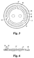
- FIG. 5 is a top view of an inlet valve for the FIG. 1 assembly.
- FIG. 6 is a side, cross-sectional view of the FIG. 5 inlet valve.
- FIG. 7 is a cross-sectional view of a pump cylinder for the FIG. 1 assembly.
- FIG. 8 is a front view of a piston in the FIG. 1 assembly.
- FIG. 9 is a front, cross-sectional view of the FIG. 8 piston.
- FIG. 10 is a bottom view of a plug in the FIG. 1 assembly.
- FIG. 11 is a side, cross-sectional view of the FIG. 10 plug.
- FIG. 12 is a cross-sectional view of the FIG. 1 assembly during filling.
- FIGS. 1 and 2 An airless pump assembly 30 according one embodiment, among others, of the present invention is illustrated in FIGS. 1 and 2 .
- the pump assembly 30 includes a container 32 for storing fluid, a follower piston 34 received in the container 32 , a pump 37 for pumping fluid from the container 32 , and a cap 39 that covers the pump 37 .
- FIGS. 1 and 2 show two cross-sectional elevations, one of which, FIG. 1 , shows the follower piston 34 at the bottom of the container 32 with the pump 37 at the top of its stroke, and the other, FIG. 2 , shows the follower piston 34 at the point where virtually the entire contents of the container 32 have been dispensed with the pump 37 at the bottom of its stroke.
- the follower piston 34 is slidably received inside a cavity 43 in the container 32 , and the follower piston 34 has upper and lower seal members 44 that seal against the container 32 .
- An upstanding ring or support 46 at base 47 of the container 32 prevents the follower piston 34 being pushed too far into the base 47 of the container 32 during packing, thereby minimizing the risk of damage to the lower piston seal member 44 .
- As fluid is dispensed from the container 32 a slight vacuum is formed, and consequently, the follower piston 34 slides up the cavity 43 to reduce the effective size of the cavity 43 .
- the container 32 has one or more vent grooves 49 as well another opening (not show) that vent the container 32 in order to prevent a vacuum from forming between the underside of the follower piston 34 and the base 47 of the container 43 as the follower piston 34 moves progressively upwards during dispensing.
- the base 47 of the container 32 further has a drive dog 52 , which allows the outside of the container 32 to be printed.
- the container 32 as well as other components have a generally cylindrical shape, but it should be appreciated that these components can be shaped differently in other embodiments.
- the pump 37 is secured to the container 32 through a snap fit type connection. Nevertheless, it should be appreciated that the pump 37 can be secured to the container 32 in other manners.
- the pump 37 includes a pump body 55 that is secured to the container 32 , an inlet valve member 57 that controls the flow of fluid into the pump 37 , a pump cylinder 60 in which a pump piston 61 is slidably disposed, an outlet valve member 64 , a pump head 66 for dispensing the fluid, a return spring 67 and a nozzle plug 68 .
- the pump body 55 has one or more ridges 72 that snap into corresponding grooves in the container 32 .
- the pump body 55 further has a cap groove 74 to which the cap 39 is secured and a retention flange 75 positioned between the ridges 72 and the cap groove 74 .
- the pump body 55 defines an inlet port 77 through which fluid is received from the container 32 , as is illustrated in FIG. 4 .
- the pump body 55 Around the inlet port 77 , the pump body 55 has a seal ridge or seat 80 that biases against and seals with the inlet valve member 57 , and surrounding the seal ridge 80 , the pump body 55 further has a valve retainer ridge 82 that aligns the inlet valve member 57 over the inlet port 77 .
- the inlet valve member 57 has a unique design that provides a number of advantages when dispensing viscous creams or other viscous fluids. As can be seen in FIGS. 5 and 6 , the inlet valve member 57 has generally flat disk shape, but as should be understood, the inlet valve member 57 can have a different overall shape in other embodiments.
- the inlet valve member 57 includes an outer peripheral ring or support member 85 and an inner seal member 87 that is connected to the outer support member 85 through two or more connection legs 88 .
- the outer support member 85 in the embodiment shown is in the form of a continuous ring, but it is envisioned that the outer support member 85 can have a different overall shape. For example, the outer support member 85 in other embodiments can include discontinuous segments.
- the inlet valve member 57 has three legs, but in other embodiments, the valve 57 can have two or even more than three legs.
- Each leg 88 includes an outer portion 90 that generally extends radially inwards from the outer support member 85 and an inner portion 91 that extends radially outwards from the seal member 87 . Between the outer 90 and inner 91 portions, each leg 88 has a circumferential portion 92 that extends between the support member and the seal member 87 in a circumferential direction such that the leg 88 generally extends around the periphery of the seal member 87 . As shown, the legs 88 are surrounded on both sides by flow apertures 94 .
- each leg 88 is radially offset about equidistantly from one another, which in this case is about one-hundred and twenty degrees (120°), so that the legs 88 are generally in the form of equal arc segments.
- the legs 88 In another embodiment where two legs 88 are used instead of three, the legs 88 almost form one-hundred and eighty degree (180°) arc segments, thereby allowing further lengthening the legs 88 for a given size of the inlet valve member 57 .
- the length and shape of the legs 88 ensures that the inner seal member can lift from the seat 80 to enable the creation of a series of large openings through the apertures 94 , which allow the easy flow of viscous fluid into the pump 37 .
- the legs 88 By having the legs 88 extend in a circumferential or peripheral manner, the legs 88 can be longer than if they just extended in a radial direction, and with the legs 88 being longer, larger flow openings can be formed. Not only does the design of the inlet vale 57 allow large apertures to be created for the easy flow of viscous fluid; it just as importantly allows the inlet valve member 57 to close in an extremely quick manner. With two or more legs 88 pulling around the seal member 87 , the seal member 87 is able to quickly seal against the seat 80 . The speed with which the seal member 87 closes onto the valve seat 80 can also be adjusted either by changing the width, thickness and/or number of the legs 88 , or by using a more or less rigid material.
- the pumping action of the pump 37 can be modified to accommodate fluids with different characteristics by simply replacing the inlet valve member 57 with one having different properties. For example, it was discovered that using three equally sized legs 88 provided desirable flow opening sizes as well as favorable closing characteristics.
- the inlet valve member 57 is made of plastic in order to avoid product contamination with metal. As noted before, it is desirable that pharmaceutical products do not come into contact with metal in order to avoid contamination. In one particular form, it was found that the inlet valve member 57 works well when produced with a polyolefin material (polyethylene/polypropylene family), which can be relatively inexpensive. It is contemplated that the inlet valve member 57 can be made of other materials, however. For instance, the inlet valve member 57 can also be made in more sophisticated polymers in applications requiring operation in heat or where chemical compatibility is a factor. Except for the spring 67 and possibly the outlet valve member 64 , all remaining components of the assembly 30 can be produced with polyolefin materials, which tend to reduce manufacturing costs. However, it should be understood that the components of the assembly 30 in other embodiments can be made of different materials, such as metal, if so desired.
- the inlet valve member 57 when assembled into the pump 37 , the inlet valve member 57 is sandwiched between the pump body 55 and the pump cylinder 60 .
- the pump body 55 in FIG. 4 has a connector 98 that extends around inlet port 77 as well as the valve retainer ridge 82 .
- the connector 98 has one or more snap grooves 99 that receive corresponding snap ridges 101 on a body engagement flange 103 that extends from the pump cylinder 60 , which is illustrated in FIG. 7 .
- a retention ridge 105 on the pump cylinder 60 clamps against the support member 85 on the inlet valve member 57 .
- the seal member 87 is biased to the closed position by the seat 80 around the inlet port 77 of the pump body 55 so that the inlet valve member 57 becomes virtually airtight during the initial priming of the pump 37 .
- the amount of pre-load bias can be varied depending on the particular requirements.
- the seat 80 in one embodiment extends about 0.3 mm high around the inlet port 77 .
- the pump cylinder 60 defines a pump cavity or chamber 108 in which the piston 61 is slidably received.
- the pump cylinder 60 and cavity 108 in FIG. 7 are generally cylindrical in shape, it is envisioned that they can have a different overall shape in other embodiments, such as a rectangular shape.
- a piston guide 110 with a guide opening 112 extends within the pump cavity 108 of the pump cylinder 60 , and a guide flange 114 extends around the guide opening 112 . Together, the piston guide 110 and the guide flange 114 define a spring retention groove 115 in which the spring 67 is received ( FIG. 1 ).
- the piston 61 has a piston head 120 that is attached to a shaft or stem 122 .
- the piston head 120 has upper and lower seal members 124 that extend at a slight angle away from the piston head 120 in order to seal against the walls of the pump cavity 108 .
- Both the piston head 120 and the shaft 122 of the piston 61 define a flow passage 127 through which the fluid is pumped.
- the pump head 66 is snap fitted to the shaft 122 , as is depicted in FIGS. 1 and 2 .
- the pump head 66 can be coupled to the shaft 122 in other manners.
- an outlet nozzle 129 with an outlet opening 130 in the pump head 66 is fluidly coupled to the flow passage 127 in the shaft 122 so that the fluid from the container 32 can be dispensed to the user.
- the spring 67 is mounted on the outside of the shaft 122 , between the pump head 66 and the pump cylinder 60 , and as a consequence, the spring 67 does not come into contact with the product being dispensed. As previously noted, this can be particularly important for pharmaceutical products where it is vital that the pharmaceutical product does not come into contact with metal.
- the pump 37 in the illustrated embodiment is configured to minimize the amount of fluid that remains at the outlet opening 130 of the pump head 66 , where the fluid may dry or harden due to contact with air. To remedy this problem, the pump 37 incorporates a suck-back feature in which fluid in the outlet opening 130 is sucked back into the pump 37 .
- the piston 61 has in the flow passage 127 a valve seat or flange 133 with a conical surface 134 , against which the outlet valve member 64 seals.
- the outlet valve member 64 acts like a check valve to permit flow of the fluid in only one direction.
- the outlet valve member 64 has a generally spherical or ball shape, but it should be understood that the outlet valve member 64 can be shaped differently in other embodiments.
- the outlet valve member 64 in other embodiments can have a cylindrical shape.
- the outlet valve member 64 in one embodiment is manufactured in a non-metallic material.
- the outlet valve member 64 in one embodiment is made of glass; however, a wide range of plastic materials can also be used in other embodiments. In systems where metal contact is not a concern, it is contemplated that the outlet valve member 64 can be made of metal.
- the flow passage 127 Downstream from the valve seat 133 , the flow passage 127 has a first portion 136 that is just slightly larger than the diameter (size) of the outlet valve member 64 so as to allow movement of the outlet valve member 64 , while still preventing the passage of fluid around the outlet valve member 64 .
- This tight fit between the outlet valve member 64 and the first portion 136 of the flow passage 127 creates a piston like fit that is used to draw fluid back from the outlet nozzle 129 during the upstroke of the piston 61 .
- the flow passage 127 Near the pump head 66 , the flow passage 127 has a second portion 138 that is larger than the first portion 136 such that the second portion 138 is sized large enough to permit fluid to flow around the outlet valve member 64 during the down stroke of the piston 61 .
- the piston 61 has ribs 140 that center the outlet valve member 64 over the first portion 136 so that the outlet valve member 64 is able to drop back into the first portion, as is shown in FIG. 2 .
- the ribs 140 extend radially inwards and along the axis of the flow passage 127 . Without the ribs 140 or some other centering structure, the outlet valve member 64 could move to one side which could cause its return to the seat 133 to be delayed, and in the worst case scenario, could cause air to be sucked back into the pump cavity 108 .
- the pump head 66 has a stop member 143 that limits the travel of the outlet valve member 64 to between the valve seat 133 and the stop member 143 .
- the pump 37 can further incorporate a spring or other type of biasing device to bias the outlet valve member 64 against the valve seat 133 .
- a spring or other type of biasing device to bias the outlet valve member 64 against the valve seat 133 .
- the pump 37 in the illustrated embodiment is a manually operated by pressing on the pump head 66 , but it should be appreciated that the pump 37 in other embodiments can be automatically actuated.
- both the cap 39 and plug 68 are removed from the pump 37 .
- the spring 67 causes the piston 61 as well as the pump head 66 to return to an extended position.
- the outlet valve member 64 travels from the second portion 138 of the flow channel 127 ( FIG. 2 ) to the first portion 136 ( FIG. 1 ).
- the outlet valve member 64 Once the outlet valve member 64 reaches the first portion 136 , the outlet valve member 64 tightly slides within the first portion 136 and acts like a virtual piston, which draws back the fluid from the outlet nozzle 129 well inboard to a position in the flow passage 127 above the outlet valve member 64 . By drawing the fluid from the nozzle 129 , the chance of fluid encrusting at the outlet opening 130 is reduced.
- the outlet valve member 64 eventually sits in the valve seat 133 to create a vacuum in the pump cavity 108 , as is shown in FIG. 1 .
- the vacuum formed in the pump cavity 108 causes the inlet valve member 57 to open, thereby providing a wide through path for the fluid from the container 32 to enter into the pump cavity 108 .
- the inlet valve member 57 shuts to prevent the fluid in the pump cavity 108 from being pushed back into the container 32 .
- the outlet valve 64 lifts off the valve seat 133 to allow fluid to be dispensed via the head nozzle 129 .
- the fluid is unable to pass around the outlet valve member 64 , but once the outlet valve member 64 reaches the larger second portion 138 of the flow passage 127 , the fluid is able to pass around the outlet valve 57 and out the nozzle 129 . Additional fluid can be dispensed by pressing and releasing the pump head 66 in the manner as described above.
- the nozzle plug 68 is plugged into the nozzle 129 to ensure that there is no leakage of the fluid.
- the plug 68 includes a handle or tab 147 that is used to pull the plug 68 from the nozzle 129 and a plug portion 148 that is plugged into the outlet opening 130 of the nozzle 129 .
- the plug portion 148 incorporates a fine vent channel 150 that is sized small enough to prevent leakage of medium to high viscosity fluids, but allows air to escape during initial priming of the pump 37 .
- the pump 37 is covered by the cap 39 .
- the cap 39 ensures that the pump head 66 cannot be inadvertently depressed during transit as well as keeps the dispensing pump 37 in prime condition and clean for display purposes.
- the cap 39 also enables the total package to withstand high top loads, which can result when quantities of packs are stacked on top of each other.
- the follower piston 34 Before filling the container 32 , the follower piston 34 is pre-assembled into the container 32 and pushed to the bottom position, as is shown in FIG. 1 . As mentioned before, the support 46 in the container 32 prevents the follower piston 34 being pushed too far into the base 47 of the container 32 .
- the design of the pump assembly 30 lends itself to “top-filling” in that the container 32 is normally passed down a filling line and filled from the top with the fluid or product being initially dispensed on top of the follower piston 34 .
- a diving nozzle 149 which is used to fill the container 32 , initially dives inside the cavity 43 to the bottom of the container 32 immediately above the follower piston 34 and progressively retracts as the fluid is dispensed, as is depicted in FIG. 12 .
- This technique ensures the minimum entrapment of air, which can be detrimental to the performance of the assembly 30 .
- the dispensing pump 37 along with the plug 68 and cap 39 , is snap-fitted to the top of the container 32 . In the process of snapping the dispensing pump 37 to the container 32 , the fluid in the container 32 forces the inlet valve member 57 to open and partially primes the pump cavity 108 .
- vent channel 150 in the plug 68 ensures that the entrapped air, which becomes pressurized as the pump 37 is snapped into place, is allowed to escape so as to ensure that there is no resistance to the opening of the inlet valve member 57 for priming purposes. Venting air through the vent channel 150 further reduces the danger of product spillage at the snap-fit between the container 32 and the pump body 55 .
Landscapes
- Reciprocating Pumps (AREA)
- Containers And Packaging Bodies Having A Special Means To Remove Contents (AREA)
- Closures For Containers (AREA)
- Loading And Unloading Of Fuel Tanks Or Ships (AREA)
- Jet Pumps And Other Pumps (AREA)
- Polysaccharides And Polysaccharide Derivatives (AREA)
Priority Applications (16)
| Application Number | Priority Date | Filing Date | Title |
|---|---|---|---|
| US10/930,010 US7654418B2 (en) | 2004-08-30 | 2004-08-30 | Airless dispensing pump |
| MXPA05006986A MXPA05006986A (es) | 2004-08-30 | 2005-06-24 | Bomba distribuidora sin aire. |
| AT05254105T ATE482769T1 (de) | 2004-08-30 | 2005-06-30 | Luftloser pumpspender |
| EP05254105A EP1629900B1 (fr) | 2004-08-30 | 2005-06-30 | Pompe distributeur sans air |
| DK05254105.9T DK1629900T3 (da) | 2004-08-30 | 2005-06-30 | Luftløs dispenserpumpe |
| BRPI0502445-5A BRPI0502445A (pt) | 2004-08-30 | 2005-06-30 | bomba dispensadora sem ar |
| DE602005023816T DE602005023816D1 (de) | 2004-08-30 | 2005-06-30 | Luftloser Pumpspender |
| AU2005202903A AU2005202903B2 (en) | 2004-08-30 | 2005-07-01 | Airless dispensing pump |
| CA2511462A CA2511462C (fr) | 2004-08-30 | 2005-07-05 | Pompe distributrice sans air |
| CNB2005100875019A CN100478082C (zh) | 2004-08-30 | 2005-07-20 | 无气分配泵及其加注方法 |
| US11/204,848 US7367476B2 (en) | 2004-08-30 | 2005-08-16 | Airless dispensing pump with tamper evidence features |
| HK06108216.5A HK1087968B (en) | 2004-08-30 | 2006-07-24 | Airless dispensing pump and a method for priming a pump |
| US12/103,397 US7690535B2 (en) | 2004-08-30 | 2008-04-15 | Airless dispensing pump with tamper evidence features |
| AU2009200740A AU2009200740B2 (en) | 2004-08-30 | 2009-02-25 | Airless dispensing pump |
| AU2009200742A AU2009200742B2 (en) | 2004-08-30 | 2009-02-25 | Airless dispensing pump |
| US12/640,371 US7891522B2 (en) | 2004-08-30 | 2009-12-17 | Airless dispensing pump |
Applications Claiming Priority (1)
| Application Number | Priority Date | Filing Date | Title |
|---|---|---|---|
| US10/930,010 US7654418B2 (en) | 2004-08-30 | 2004-08-30 | Airless dispensing pump |
Related Child Applications (2)
| Application Number | Title | Priority Date | Filing Date |
|---|---|---|---|
| US11/204,848 Continuation-In-Part US7367476B2 (en) | 2004-08-30 | 2005-08-16 | Airless dispensing pump with tamper evidence features |
| US12/640,371 Continuation US7891522B2 (en) | 2004-08-30 | 2009-12-17 | Airless dispensing pump |
Publications (2)
| Publication Number | Publication Date |
|---|---|
| US20060043118A1 US20060043118A1 (en) | 2006-03-02 |
| US7654418B2 true US7654418B2 (en) | 2010-02-02 |
Family
ID=34981315
Family Applications (3)
| Application Number | Title | Priority Date | Filing Date |
|---|---|---|---|
| US10/930,010 Active 2027-09-29 US7654418B2 (en) | 2004-08-30 | 2004-08-30 | Airless dispensing pump |
| US12/103,397 Expired - Lifetime US7690535B2 (en) | 2004-08-30 | 2008-04-15 | Airless dispensing pump with tamper evidence features |
| US12/640,371 Expired - Lifetime US7891522B2 (en) | 2004-08-30 | 2009-12-17 | Airless dispensing pump |
Family Applications After (2)
| Application Number | Title | Priority Date | Filing Date |
|---|---|---|---|
| US12/103,397 Expired - Lifetime US7690535B2 (en) | 2004-08-30 | 2008-04-15 | Airless dispensing pump with tamper evidence features |
| US12/640,371 Expired - Lifetime US7891522B2 (en) | 2004-08-30 | 2009-12-17 | Airless dispensing pump |
Country Status (10)
| Country | Link |
|---|---|
| US (3) | US7654418B2 (fr) |
| EP (1) | EP1629900B1 (fr) |
| CN (1) | CN100478082C (fr) |
| AT (1) | ATE482769T1 (fr) |
| AU (3) | AU2005202903B2 (fr) |
| BR (1) | BRPI0502445A (fr) |
| CA (1) | CA2511462C (fr) |
| DE (1) | DE602005023816D1 (fr) |
| DK (1) | DK1629900T3 (fr) |
| MX (1) | MXPA05006986A (fr) |
Cited By (22)
| Publication number | Priority date | Publication date | Assignee | Title |
|---|---|---|---|---|
| US20080296319A1 (en) * | 2005-12-16 | 2008-12-04 | Alfons Bockmann | Dispenser For Liquid and/or Pasty Masses |
| US20090065531A1 (en) * | 2006-05-05 | 2009-03-12 | Airlessystems | Fluid product dispensing member and dispenser comprising same |
| US20100089945A1 (en) * | 2004-08-30 | 2010-04-15 | Rieke Corporation | Airless dispensing pump |
| US20100098480A1 (en) * | 2008-10-20 | 2010-04-22 | Byeon Jae Sam | Airless type cosmetics vessel |
| US20100294795A1 (en) * | 2007-11-07 | 2010-11-25 | Boehm Andreas J | One-piece vented piston |
| US20120035556A1 (en) * | 2010-08-05 | 2012-02-09 | Graceway Parmaceuticals, LLC | Pump systems and methods for storing and dispensing a plurality of precisely measured unit-doses of imiquimod cream |
| US8528795B2 (en) | 2008-09-01 | 2013-09-10 | Rieke Corporation | Liquid dosing devices |
| US8556130B2 (en) | 2010-01-14 | 2013-10-15 | Rieke Corporation | Pump dispensers |
| US20140008396A1 (en) * | 2010-07-01 | 2014-01-09 | Werner Holzmann | Metering dispenser |
| US8939323B2 (en) | 2010-07-01 | 2015-01-27 | Rieke Corporation | Dispensers |
| US20150174120A1 (en) * | 2009-04-01 | 2015-06-25 | Valeant Pharmaceuticals International, Inc. | Multidose package, course and method of treatment for delivering predetermined multiple doses of a pharmaceutical |
| US9211559B2 (en) | 2010-07-01 | 2015-12-15 | Rieke Corporation | Dispensers |
| US9433960B2 (en) | 2008-09-01 | 2016-09-06 | Rieke Corporation | Liquid dosing devices |
| WO2018064688A1 (fr) * | 2016-09-30 | 2018-04-05 | Shordee Products Llc | Brosse de distribution de fluide |
| US10307779B2 (en) | 2015-05-01 | 2019-06-04 | St&T Packaging Pte. Ltd. | Dual-chambered bottles for storing and dispensing of fluid and semi-fluid materials |
| US20190255547A1 (en) * | 2016-07-18 | 2019-08-22 | Rpc Bramlage Gmbh | Dispenser for liquid to pasty compositions |
| US10391515B1 (en) * | 2018-05-11 | 2019-08-27 | Andrew Norman Kerlin | Viscous fluid applicator pump |
| US10751260B2 (en) | 2013-10-22 | 2020-08-25 | Jag Mayer Pty Ltd | Dispenser |
| US10967059B2 (en) | 2013-09-19 | 2021-04-06 | Allovate, Llc | Toothpaste for delivery of allergens to oral mucosa |
| US11471905B1 (en) | 2021-09-23 | 2022-10-18 | Apackaging Group Llc | All plastic airless pump dispenser |
| US20230021501A1 (en) * | 2019-12-18 | 2023-01-26 | Glaxosmithkline Consumer Healthcare Holdings (Us) Llc | Tamper-proof and controlled dosing container |
| US12508612B2 (en) * | 2020-11-02 | 2025-12-30 | Aptar France Sas | Device for dispensing a fluid product |
Families Citing this family (36)
| Publication number | Priority date | Publication date | Assignee | Title |
|---|---|---|---|---|
| DE602006004849D1 (de) * | 2006-05-15 | 2009-03-05 | Wintek Sarl | Spender für fliessfähige Produkte mit einer Druckkolbenpumpe und einer Membrane |
| US8974410B2 (en) | 2006-10-30 | 2015-03-10 | Vidacare LLC | Apparatus and methods to communicate fluids and/or support intraosseous devices |
| ITRM20070241A1 (it) * | 2007-04-24 | 2008-10-25 | Emsar Spa | Dispositivo di collegamento di micropompe a flaconi. |
| DK2242409T3 (da) | 2008-02-18 | 2020-02-03 | Essity Hygiene & Health Ab | Engangspumpe med tilbagesugningsmekanisme |
| KR200440665Y1 (ko) * | 2008-03-25 | 2008-06-24 | (주)연우 | 펌핑식 화장품용기 |
| KR101064493B1 (ko) * | 2009-07-31 | 2011-09-14 | (주)연우 | 내용물의 리필이 가능한 지관용기 |
| CA2776795C (fr) * | 2009-10-09 | 2018-01-02 | The University Of Salford | Appareil de distribution de liquide |
| FR2956098B1 (fr) * | 2010-02-11 | 2012-03-30 | Airlessystems | Distributeur de produit fluide. |
| US20110240677A1 (en) * | 2010-03-03 | 2011-10-06 | Walter Dwyer | Airless double-piston double-action pump and cosmetics bottle dispensing device |
| FR2966129B1 (fr) * | 2010-10-18 | 2012-10-19 | Rexam Dispensing Sys | Procede et flacon de distribution d'un produit fluide |
| KR101258142B1 (ko) * | 2011-06-30 | 2013-04-25 | (주)연우 | 내용물의 리필이 가능한 지관용기 |
| US9248462B2 (en) | 2011-12-01 | 2016-02-02 | Yonwoo Co., Ltd. | Airless pump system |
| CN202321216U (zh) * | 2011-12-14 | 2012-07-11 | 东莞怡信磁碟有限公司 | 一种可充式喷液瓶 |
| KR101343909B1 (ko) * | 2012-02-29 | 2013-12-20 | (주)연우 | 이종 내용물의 배출구조를 갖는 펌핑식 화장품용기 및 이의 제조방법 |
| GB201212042D0 (en) | 2012-07-05 | 2012-08-22 | Rieke Corp | Pump dispensers |
| CN105188850A (zh) | 2013-05-16 | 2015-12-23 | 宝洁公司 | 毛发增稠组合物及使用方法 |
| CN105873685B (zh) * | 2014-01-13 | 2019-04-12 | 维实洛克Mwv有限责任公司 | 带有盘形弹簧的分配泵 |
| KR101501027B1 (ko) * | 2014-06-16 | 2015-03-12 | (주)연우 | 캡슐 토출용 펌프 용기 |
| CA2964819A1 (fr) | 2014-10-20 | 2016-04-28 | Rieke Packaging Systems Limited | Distributeurs a pompe |
| FR3028571B1 (fr) * | 2014-11-14 | 2019-09-13 | Aptar France Sas | Pompe manuelle |
| AR101299A1 (es) | 2015-07-24 | 2016-12-07 | Valvulas Prec De Argentina S A C I | Precinto con traba de seguridad desgarrable, aplicable a cabezales dispensadores de líquidos |
| DE102016105998A1 (de) * | 2015-09-23 | 2017-03-23 | Rpc Bramlage Gmbh | Spender für flüssige bis pastöse Massen |
| FR3042181B1 (fr) | 2015-10-08 | 2020-02-28 | Qualipac | Dispositif de conditionnement et distribution par dose d'un produit fluide |
| CN105346823A (zh) * | 2015-12-01 | 2016-02-24 | 上海洁诺德塑胶制品有限公司 | 自动泵压式牙膏包装瓶 |
| FR3048236B1 (fr) * | 2016-02-29 | 2019-07-12 | Albea Le Treport | Systeme de distribution de produit pour flacon |
| DE102017100712A1 (de) * | 2017-01-16 | 2018-07-19 | Atlas Copco Ias Gmbh | Vorrichtung und Verfahren zum Fördern von viskosem Material |
| CN111050927A (zh) * | 2017-09-01 | 2020-04-21 | 巴斯夫涂料有限公司 | 计量和混合装置 |
| WO2019042772A1 (fr) | 2017-09-01 | 2019-03-07 | Basf Coatings Gmbh | Dispositif de dosage et de mélange |
| KR102649366B1 (ko) * | 2018-09-18 | 2024-03-20 | 주식회사 엘지생활건강 | 화장품 |
| KR102649345B1 (ko) * | 2018-09-18 | 2024-03-20 | 주식회사 엘지생활건강 | 화장품 |
| CN110182459B (zh) * | 2019-05-31 | 2024-02-23 | 佛山市长拓包装科技有限公司 | 防漏液泡沫泵 |
| US10898032B1 (en) * | 2020-05-18 | 2021-01-26 | Channing Wells | Portable multi-component fluid and paper based product dispenser |
| US12194482B2 (en) | 2021-05-22 | 2025-01-14 | Anhui Jnd Plastic Packaging Co., Ltd. | Pump head and container with pump head |
| CN113202711B (zh) * | 2021-05-22 | 2023-11-07 | 上海洁诺德塑胶制品有限公司 | 一种泵头及具有该泵头的容器 |
| US11679403B1 (en) | 2022-02-02 | 2023-06-20 | Ries Ries Inc | Travel dispenser for dispensing a fluid |
| WO2023203124A1 (fr) | 2022-04-20 | 2023-10-26 | Assistance Publique - Hôpitaux De Paris | Nouvelle formulation d'atropine |
Citations (68)
| Publication number | Priority date | Publication date | Assignee | Title |
|---|---|---|---|---|
| US3403823A (en) | 1966-10-03 | 1968-10-01 | Valve Corp Of America | Tamper-proof actuator cap |
| US4039139A (en) | 1974-08-22 | 1977-08-02 | Bird F M | Ventilator and method |
| US4139311A (en) | 1976-05-03 | 1979-02-13 | Willy Lorscheidt | Dispensing cartridge having an improved automatic filler stick positioning mechanism |
| US4154371A (en) | 1976-03-19 | 1979-05-15 | Henkel Kommanditgesellschaft Auf Aktien | Dispensing container |
| US4323175A (en) | 1979-04-19 | 1982-04-06 | Josef Eckert | Dispenser utilizing a follower and delivery device for dispensing pastes, creams, etc. |
| GB2103298A (en) | 1981-07-27 | 1983-02-16 | Realex Corp | Tamper-proof clip for uplocking plungers of pump dispensers |
| US4394939A (en) | 1980-09-22 | 1983-07-26 | Henkel Kommanditgesellschaft Auf Aktien | Dispenser container for viscous fluids |
| US4402431A (en) * | 1980-09-22 | 1983-09-06 | Henkel Kommanditgesellschaft Auf Aktien | Dispenser container with compressible pump |
| US4438871A (en) | 1981-05-27 | 1984-03-27 | Wischerath And Schreiner Kg | Dispenser |
| US4479589A (en) | 1982-06-07 | 1984-10-30 | Realex Corporation | Plunger lock for manual dispensing pump |
| US4485943A (en) | 1982-03-08 | 1984-12-04 | Joachim Czech | Dispenser for liquids or pasty products |
| US4558821A (en) | 1983-03-03 | 1985-12-17 | Canyon Corporation | Trigger-type sprayer with integrally formed housing, trigger, nozzle and cylinder |
| US4564130A (en) | 1982-06-29 | 1986-01-14 | Josef Wischerath Gmbh & Co., Kg | Dispenser for paste-like products |
| US4579147A (en) | 1984-11-30 | 1986-04-01 | Paul H. Gunderson | Outlet valve for pressurized diving suit |
| US4589574A (en) | 1983-11-30 | 1986-05-20 | Realex Corporation | Dispensing pump having collar-to-body anti-rotation interlock |
| US4781483A (en) | 1986-10-03 | 1988-11-01 | Willy Lorscheidt | Device for exposing a mass stored in a container |
| US4889262A (en) | 1988-06-07 | 1989-12-26 | L'oreal, S. A. | Locking system for pump dispenser |
| USRE33247E (en) | 1982-01-19 | 1990-07-03 | Gap Gesellschaft Fur Auswertungen Und Patente Ag | Dispenser for paste-like products |
| US4945941A (en) | 1990-03-05 | 1990-08-07 | Vilter Manufacturing Corporation | Means to reduce vibration in check valves and stop/check valves caused by pulsating low fluid flow |
| US4991746A (en) | 1989-07-07 | 1991-02-12 | Emson Research Inc. | Modular pump having a locking rotatable sleeve |
| US5096094A (en) | 1989-09-08 | 1992-03-17 | Aerosol Inventions And Development S.A. A.I.D. S.A. | Manual pump pre-orientable on the neck of a container |
| WO1992022467A1 (fr) * | 1991-06-14 | 1992-12-23 | Gerd Hermann | Soupape pour recipients a comprimer |
| US5209044A (en) * | 1991-07-11 | 1993-05-11 | Innovative Automation Inc. | Automatic tube filling device and process |
| US5310112A (en) | 1992-03-05 | 1994-05-10 | Philip Meshberg | Valved gasket for dispenser |
| US5356043A (en) | 1993-08-30 | 1994-10-18 | Ideal Ideas, Inc. | Child resistant cap with safety collar for sprayers |
| US5397035A (en) | 1992-09-28 | 1995-03-14 | The English Glass Company Limited | Dispenser pumps |
| US5445299A (en) | 1994-05-02 | 1995-08-29 | Calmar Inc. | Tamper evident lock for liquid pump dispenser |
| US5497915A (en) | 1991-08-16 | 1996-03-12 | The English Glass Company Limited | Dispenser pumps |
| US5615806A (en) | 1996-05-31 | 1997-04-01 | Calmar-Albert Gmbh | Plunger lock-up dispenser |
| US5655685A (en) | 1995-05-31 | 1997-08-12 | Clayton Corporation | Closure assembly for a container having a tamper-evident pouring spout closure member |
| US5664703A (en) | 1994-02-28 | 1997-09-09 | The Procter & Gamble Company | Pump device with collapsible pump chamber having supply container venting system and integral shipping seal |
| US5673821A (en) | 1991-08-31 | 1997-10-07 | Smithkline Beecham Plc | Dispensing device for two fluid materials |
| US5816453A (en) | 1994-03-24 | 1998-10-06 | The English Glass Company Limited | Dispenser pump |
| US5842605A (en) * | 1996-07-24 | 1998-12-01 | Lehmkuhl; Robert A. | Resuable dispenser for paste, lotion and cream-like materials |
| US5884820A (en) | 1994-11-11 | 1999-03-23 | Spraysol Gmbh | Dispensers for liquid products |
| US5924604A (en) | 1995-01-27 | 1999-07-20 | Yoshino Kogyosho Co., Ltd. | Liquid jetting pump with passageways for dispensing liquids |
| WO1999039982A2 (fr) | 1998-02-09 | 1999-08-12 | Jokey Plastik Wipperfürth GmbH | Pot de peinture |
| US5941422A (en) | 1998-04-06 | 1999-08-24 | Owens-Brockway Plastic Products Inc. | Liquid containing and dispensing package |
| US5975370A (en) | 1998-03-16 | 1999-11-02 | Owens-Illinois Closure Inc. | Tamper-evident plunger-hold-down attachment for pump dispenser |
| US5992442A (en) | 1997-05-29 | 1999-11-30 | Urquhart; Edward F. | Relief valve for use with hermetically sealed flexible container |
| US6213633B1 (en) | 1996-06-11 | 2001-04-10 | Smithkline Beecham Consumer Healthcare Gmbh | Mixing and dispensing device |
| US6240979B1 (en) | 1997-09-23 | 2001-06-05 | Rpc Wiko Gmbh & Co. Kg | Dispenser, and method of filling the same |
| US6257440B1 (en) | 1999-04-08 | 2001-07-10 | Ropak Corporation | Container handle and related methods |
| US6269981B1 (en) | 1999-12-20 | 2001-08-07 | Reagan Nielsen | Oil dispensing apparatus |
| US20010019068A1 (en) | 1999-10-22 | 2001-09-06 | Bloom Kenneth S. | Pump dispenser piston provided with a plastic inlet check valve insert |
| US20010025863A1 (en) | 1997-09-23 | 2001-10-04 | Willi Lorscheidt | Dispensing pump, dispenser and dispenser unit-assembly |
| US6309124B1 (en) | 1999-01-15 | 2001-10-30 | L'oreal | Device for dispensing and applying a product |
| US6321908B1 (en) | 1998-05-15 | 2001-11-27 | Rpc Wiko Gmbh & Co. Kg | Multi-chamber container |
| CN2483350Y (zh) | 2001-05-16 | 2002-03-27 | 丁要武 | 具有防进液气道的乳液泵 |
| CN2493753Y (zh) | 2001-05-07 | 2002-05-29 | 孙秉忠 | 乳液泵 |
| WO2002043872A2 (fr) | 2000-12-01 | 2002-06-06 | Dispensing Patents International Llc | Dispositif de pulverisation a obturateur de buse |
| CN2521166Y (zh) | 2002-01-31 | 2002-11-20 | 林添大 | 乳液真空泵 |
| US6533145B2 (en) | 2000-12-19 | 2003-03-18 | Kimberly-Clark Worldwide, Inc. | Self-contained viscous liquid dispenser |
| WO2003028898A1 (fr) | 2001-10-01 | 2003-04-10 | Rieke Packaging Systems Limited | Pompes pour distributeurs |
| US20030075567A1 (en) | 2000-05-26 | 2003-04-24 | Stefano Santagiuliana | Bellows pump for delivery of liquids |
| US20030089738A1 (en) | 2001-11-13 | 2003-05-15 | Unilever Home & Personal Care, Usa | Dose dispensing pump for dispensing two or more materials |
| US20030168475A1 (en) | 2002-02-05 | 2003-09-11 | Rpc Wiko Gmbh & Co. Kg | Dispenser for flowable products |
| US20030168477A1 (en) | 2002-03-05 | 2003-09-11 | Rpc Wiko Gmbh & Co. Kg | Dispenser for flowable products with spherically encapsulated components |
| US20030231923A1 (en) | 2002-03-11 | 2003-12-18 | Wolfgang Heukamp | Dispenser for free-flowing products |
| US20040007601A1 (en) * | 2002-06-26 | 2004-01-15 | Masatoshi Masuda | Valve mechanism for tube-type fluid container |
| EP1384517A2 (fr) | 2002-07-24 | 2004-01-28 | Masuda Masatoshi | Pompe de décharge |
| US6752153B1 (en) | 1998-08-14 | 2004-06-22 | Rpc Wiko Gmbh & Co. Kg | Inhalator comprising a dosage counting device |
| US6772916B1 (en) | 2002-07-08 | 2004-08-10 | Joseph S. Kanfer | Hidden locking system for wall-mounted dispenser |
| US20040206783A1 (en) | 2001-05-02 | 2004-10-21 | Ulrike Danne | Dispenser for a cream-type material or material which can be deposited by applying it a surface |
| US20040206781A1 (en) | 2001-06-29 | 2004-10-21 | Willy Lorscheidt | Dispenser for paste-like products |
| WO2005021395A1 (fr) | 2003-08-30 | 2005-03-10 | Sang-Hoon Kim | Bouchon de bouteille et bouteille comprenant celui-ci |
| US7059501B2 (en) * | 2002-06-10 | 2006-06-13 | Masatoshi Masuda | Valve mechanism for tube-type fluid container |
| US7111761B2 (en) * | 2003-07-03 | 2006-09-26 | Masatoshi Masuda | Fluid discharge pump and fluid container |
Family Cites Families (18)
| Publication number | Priority date | Publication date | Assignee | Title |
|---|---|---|---|---|
| US2991913A (en) * | 1957-01-18 | 1961-07-11 | Goth Imre | Combined pouring and sealing devices for containers |
| US2982448A (en) * | 1959-11-30 | 1961-05-02 | Henry K Leonard | Closures for dispensing containers |
| US3255928A (en) * | 1963-05-20 | 1966-06-14 | Clark Mfg Co J L | Tamperproof closure for dispensing container |
| GB1224260A (en) * | 1969-07-03 | 1971-03-10 | Massey Ltd B & S | Improvements in upsetting or forging machines |
| US4971227A (en) * | 1989-06-02 | 1990-11-20 | Calmar, Inc. | Manually actuated dispensing pump sprayer having a removable nozzle locking element |
| US5040702A (en) * | 1989-06-02 | 1991-08-20 | Calmar Inc. | Manually actuated dispensing pump sprayer having a removable nozzle locking element |
| US5067531A (en) * | 1989-10-30 | 1991-11-26 | Kenneth Herzog | Bench top container filler |
| US5158233A (en) * | 1991-10-07 | 1992-10-27 | Contico International, Inc. | Foamer trigger dispenser with sealing device |
| US5482186A (en) * | 1994-06-20 | 1996-01-09 | Calmar Inc. | Removable lock element for immobilizing rotation of a trigger sprayer nozzle |
| US5706983B1 (en) * | 1995-08-18 | 1999-08-24 | Calmar Inc | Trigger sprayer having a nozzle cover |
| US5655806A (en) * | 1995-11-01 | 1997-08-12 | Halladay; James J. | Tongs with tapered jaws |
| US5850948A (en) | 1996-09-13 | 1998-12-22 | Valois S.A. | Finger-operable pump with piston biasing post |
| JP3101650B2 (ja) * | 1997-10-08 | 2000-10-23 | 明智セラミックス株式会社 | 連続鋳造用ノズル |
| US5842805A (en) * | 1997-11-03 | 1998-12-01 | Rexam Cosmetic Packaging, Inc. | Cosmetic container having a cooperating cosmetic carrier and inner sleeve |
| US6491207B1 (en) * | 1999-12-10 | 2002-12-10 | General Electric Company | Weld repair of directionally solidified articles |
| US6269961B1 (en) * | 2000-01-14 | 2001-08-07 | M. Kamenstein, Inc. | Foldable support rack |
| US7654418B2 (en) * | 2004-08-30 | 2010-02-02 | Rieke Corporation | Airless dispensing pump |
| US7367476B2 (en) * | 2004-08-30 | 2008-05-06 | Rieke Corporation | Airless dispensing pump with tamper evidence features |
-
2004
- 2004-08-30 US US10/930,010 patent/US7654418B2/en active Active
-
2005
- 2005-06-24 MX MXPA05006986A patent/MXPA05006986A/es active IP Right Grant
- 2005-06-30 BR BRPI0502445-5A patent/BRPI0502445A/pt not_active Application Discontinuation
- 2005-06-30 DE DE602005023816T patent/DE602005023816D1/de not_active Expired - Lifetime
- 2005-06-30 DK DK05254105.9T patent/DK1629900T3/da active
- 2005-06-30 AT AT05254105T patent/ATE482769T1/de not_active IP Right Cessation
- 2005-06-30 EP EP05254105A patent/EP1629900B1/fr not_active Expired - Lifetime
- 2005-07-01 AU AU2005202903A patent/AU2005202903B2/en not_active Ceased
- 2005-07-05 CA CA2511462A patent/CA2511462C/fr not_active Expired - Fee Related
- 2005-07-20 CN CNB2005100875019A patent/CN100478082C/zh not_active Expired - Lifetime
-
2008
- 2008-04-15 US US12/103,397 patent/US7690535B2/en not_active Expired - Lifetime
-
2009
- 2009-02-25 AU AU2009200742A patent/AU2009200742B2/en not_active Ceased
- 2009-02-25 AU AU2009200740A patent/AU2009200740B2/en not_active Ceased
- 2009-12-17 US US12/640,371 patent/US7891522B2/en not_active Expired - Lifetime
Patent Citations (73)
| Publication number | Priority date | Publication date | Assignee | Title |
|---|---|---|---|---|
| US3403823A (en) | 1966-10-03 | 1968-10-01 | Valve Corp Of America | Tamper-proof actuator cap |
| US4039139A (en) | 1974-08-22 | 1977-08-02 | Bird F M | Ventilator and method |
| US4154371A (en) | 1976-03-19 | 1979-05-15 | Henkel Kommanditgesellschaft Auf Aktien | Dispensing container |
| US4139311A (en) | 1976-05-03 | 1979-02-13 | Willy Lorscheidt | Dispensing cartridge having an improved automatic filler stick positioning mechanism |
| US4323175A (en) | 1979-04-19 | 1982-04-06 | Josef Eckert | Dispenser utilizing a follower and delivery device for dispensing pastes, creams, etc. |
| US4402431A (en) * | 1980-09-22 | 1983-09-06 | Henkel Kommanditgesellschaft Auf Aktien | Dispenser container with compressible pump |
| US4394939A (en) | 1980-09-22 | 1983-07-26 | Henkel Kommanditgesellschaft Auf Aktien | Dispenser container for viscous fluids |
| US4438871A (en) | 1981-05-27 | 1984-03-27 | Wischerath And Schreiner Kg | Dispenser |
| GB2103298A (en) | 1981-07-27 | 1983-02-16 | Realex Corp | Tamper-proof clip for uplocking plungers of pump dispensers |
| USRE33247E (en) | 1982-01-19 | 1990-07-03 | Gap Gesellschaft Fur Auswertungen Und Patente Ag | Dispenser for paste-like products |
| US4485943A (en) | 1982-03-08 | 1984-12-04 | Joachim Czech | Dispenser for liquids or pasty products |
| US4479589A (en) | 1982-06-07 | 1984-10-30 | Realex Corporation | Plunger lock for manual dispensing pump |
| US4564130A (en) | 1982-06-29 | 1986-01-14 | Josef Wischerath Gmbh & Co., Kg | Dispenser for paste-like products |
| US4558821A (en) | 1983-03-03 | 1985-12-17 | Canyon Corporation | Trigger-type sprayer with integrally formed housing, trigger, nozzle and cylinder |
| US4589574A (en) | 1983-11-30 | 1986-05-20 | Realex Corporation | Dispensing pump having collar-to-body anti-rotation interlock |
| US4579147A (en) | 1984-11-30 | 1986-04-01 | Paul H. Gunderson | Outlet valve for pressurized diving suit |
| US4781483A (en) | 1986-10-03 | 1988-11-01 | Willy Lorscheidt | Device for exposing a mass stored in a container |
| US4889262A (en) | 1988-06-07 | 1989-12-26 | L'oreal, S. A. | Locking system for pump dispenser |
| US4991746A (en) | 1989-07-07 | 1991-02-12 | Emson Research Inc. | Modular pump having a locking rotatable sleeve |
| US5096094A (en) | 1989-09-08 | 1992-03-17 | Aerosol Inventions And Development S.A. A.I.D. S.A. | Manual pump pre-orientable on the neck of a container |
| US4945941A (en) | 1990-03-05 | 1990-08-07 | Vilter Manufacturing Corporation | Means to reduce vibration in check valves and stop/check valves caused by pulsating low fluid flow |
| WO1992022467A1 (fr) * | 1991-06-14 | 1992-12-23 | Gerd Hermann | Soupape pour recipients a comprimer |
| US5209044A (en) * | 1991-07-11 | 1993-05-11 | Innovative Automation Inc. | Automatic tube filling device and process |
| US5497915A (en) | 1991-08-16 | 1996-03-12 | The English Glass Company Limited | Dispenser pumps |
| US5823394A (en) | 1991-08-31 | 1998-10-20 | Smithkline Beecham P.L.C. | Dispensing device for two fluid materials |
| US5673821A (en) | 1991-08-31 | 1997-10-07 | Smithkline Beecham Plc | Dispensing device for two fluid materials |
| US5310112A (en) | 1992-03-05 | 1994-05-10 | Philip Meshberg | Valved gasket for dispenser |
| US5397035A (en) | 1992-09-28 | 1995-03-14 | The English Glass Company Limited | Dispenser pumps |
| US5356043A (en) | 1993-08-30 | 1994-10-18 | Ideal Ideas, Inc. | Child resistant cap with safety collar for sprayers |
| US5664703A (en) | 1994-02-28 | 1997-09-09 | The Procter & Gamble Company | Pump device with collapsible pump chamber having supply container venting system and integral shipping seal |
| US5816453A (en) | 1994-03-24 | 1998-10-06 | The English Glass Company Limited | Dispenser pump |
| US5445299A (en) | 1994-05-02 | 1995-08-29 | Calmar Inc. | Tamper evident lock for liquid pump dispenser |
| US5884820A (en) | 1994-11-11 | 1999-03-23 | Spraysol Gmbh | Dispensers for liquid products |
| US5924604A (en) | 1995-01-27 | 1999-07-20 | Yoshino Kogyosho Co., Ltd. | Liquid jetting pump with passageways for dispensing liquids |
| CN1378883A (zh) | 1995-01-27 | 2002-11-13 | 株式会社吉野工业所 | 液体喷出泵 |
| US5655685A (en) | 1995-05-31 | 1997-08-12 | Clayton Corporation | Closure assembly for a container having a tamper-evident pouring spout closure member |
| US5615806A (en) | 1996-05-31 | 1997-04-01 | Calmar-Albert Gmbh | Plunger lock-up dispenser |
| US6213633B1 (en) | 1996-06-11 | 2001-04-10 | Smithkline Beecham Consumer Healthcare Gmbh | Mixing and dispensing device |
| US5842605A (en) * | 1996-07-24 | 1998-12-01 | Lehmkuhl; Robert A. | Resuable dispenser for paste, lotion and cream-like materials |
| US5992442A (en) | 1997-05-29 | 1999-11-30 | Urquhart; Edward F. | Relief valve for use with hermetically sealed flexible container |
| US20010025863A1 (en) | 1997-09-23 | 2001-10-04 | Willi Lorscheidt | Dispensing pump, dispenser and dispenser unit-assembly |
| US6240979B1 (en) | 1997-09-23 | 2001-06-05 | Rpc Wiko Gmbh & Co. Kg | Dispenser, and method of filling the same |
| US6371333B2 (en) | 1997-09-23 | 2002-04-16 | Josef Wischerath Gmbh & Co. Kg | Dispensing pump, dispenser and dispenser unit-assembly |
| WO1999039982A2 (fr) | 1998-02-09 | 1999-08-12 | Jokey Plastik Wipperfürth GmbH | Pot de peinture |
| US5975370A (en) | 1998-03-16 | 1999-11-02 | Owens-Illinois Closure Inc. | Tamper-evident plunger-hold-down attachment for pump dispenser |
| US5941422A (en) | 1998-04-06 | 1999-08-24 | Owens-Brockway Plastic Products Inc. | Liquid containing and dispensing package |
| US6321908B1 (en) | 1998-05-15 | 2001-11-27 | Rpc Wiko Gmbh & Co. Kg | Multi-chamber container |
| US6752153B1 (en) | 1998-08-14 | 2004-06-22 | Rpc Wiko Gmbh & Co. Kg | Inhalator comprising a dosage counting device |
| US6309124B1 (en) | 1999-01-15 | 2001-10-30 | L'oreal | Device for dispensing and applying a product |
| US6257440B1 (en) | 1999-04-08 | 2001-07-10 | Ropak Corporation | Container handle and related methods |
| US20010019068A1 (en) | 1999-10-22 | 2001-09-06 | Bloom Kenneth S. | Pump dispenser piston provided with a plastic inlet check valve insert |
| US6269981B1 (en) | 1999-12-20 | 2001-08-07 | Reagan Nielsen | Oil dispensing apparatus |
| US20030075567A1 (en) | 2000-05-26 | 2003-04-24 | Stefano Santagiuliana | Bellows pump for delivery of liquids |
| WO2002043872A2 (fr) | 2000-12-01 | 2002-06-06 | Dispensing Patents International Llc | Dispositif de pulverisation a obturateur de buse |
| US6533145B2 (en) | 2000-12-19 | 2003-03-18 | Kimberly-Clark Worldwide, Inc. | Self-contained viscous liquid dispenser |
| US20040206783A1 (en) | 2001-05-02 | 2004-10-21 | Ulrike Danne | Dispenser for a cream-type material or material which can be deposited by applying it a surface |
| CN2493753Y (zh) | 2001-05-07 | 2002-05-29 | 孙秉忠 | 乳液泵 |
| CN2483350Y (zh) | 2001-05-16 | 2002-03-27 | 丁要武 | 具有防进液气道的乳液泵 |
| US6890162B2 (en) * | 2001-05-16 | 2005-05-10 | Ding Yao Wu | Emulsion pump with an air channel preventing liquid entrance |
| US20040206781A1 (en) | 2001-06-29 | 2004-10-21 | Willy Lorscheidt | Dispenser for paste-like products |
| WO2003028898A1 (fr) | 2001-10-01 | 2003-04-10 | Rieke Packaging Systems Limited | Pompes pour distributeurs |
| US20030089738A1 (en) | 2001-11-13 | 2003-05-15 | Unilever Home & Personal Care, Usa | Dose dispensing pump for dispensing two or more materials |
| US6729501B2 (en) * | 2001-11-13 | 2004-05-04 | Unilever Home & Personal Care Usa, Division Of Conopco, Inc. | Dose dispensing pump for dispensing two or more materials |
| CN2521166Y (zh) | 2002-01-31 | 2002-11-20 | 林添大 | 乳液真空泵 |
| US20030168475A1 (en) | 2002-02-05 | 2003-09-11 | Rpc Wiko Gmbh & Co. Kg | Dispenser for flowable products |
| US20030168477A1 (en) | 2002-03-05 | 2003-09-11 | Rpc Wiko Gmbh & Co. Kg | Dispenser for flowable products with spherically encapsulated components |
| US20030231923A1 (en) | 2002-03-11 | 2003-12-18 | Wolfgang Heukamp | Dispenser for free-flowing products |
| US7059501B2 (en) * | 2002-06-10 | 2006-06-13 | Masatoshi Masuda | Valve mechanism for tube-type fluid container |
| US20040007601A1 (en) * | 2002-06-26 | 2004-01-15 | Masatoshi Masuda | Valve mechanism for tube-type fluid container |
| US6772916B1 (en) | 2002-07-08 | 2004-08-10 | Joseph S. Kanfer | Hidden locking system for wall-mounted dispenser |
| EP1384517A2 (fr) | 2002-07-24 | 2004-01-28 | Masuda Masatoshi | Pompe de décharge |
| US7111761B2 (en) * | 2003-07-03 | 2006-09-26 | Masatoshi Masuda | Fluid discharge pump and fluid container |
| WO2005021395A1 (fr) | 2003-08-30 | 2005-03-10 | Sang-Hoon Kim | Bouchon de bouteille et bouteille comprenant celui-ci |
Non-Patent Citations (5)
| Title |
|---|
| EP Search Report dated Feb. 5, 2008 issued in EP Application No. 06253488.8. |
| European Patent Application 06 25 3488 Search Report mailed Apr. 7, 2008. |
| European Patent Application No. 05 25 4105 Search Report mailed Nov. 24, 2008. |
| First Office Action dated Jan. 4, 2008 in Chinese Patent Application No. 200510087501.9, application filed Jul. 20, 2005. |
| Machine Translation of WO 92/22467 A1 to Herrmann. |
Cited By (36)
| Publication number | Priority date | Publication date | Assignee | Title |
|---|---|---|---|---|
| US20100089945A1 (en) * | 2004-08-30 | 2010-04-15 | Rieke Corporation | Airless dispensing pump |
| US7891522B2 (en) * | 2004-08-30 | 2011-02-22 | Rieke Corporation | Airless dispensing pump |
| US20080296319A1 (en) * | 2005-12-16 | 2008-12-04 | Alfons Bockmann | Dispenser For Liquid and/or Pasty Masses |
| US20090065531A1 (en) * | 2006-05-05 | 2009-03-12 | Airlessystems | Fluid product dispensing member and dispenser comprising same |
| US8118195B2 (en) * | 2006-05-05 | 2012-02-21 | Airlessystems | Fluid product dispensing member and dispenser comprising same |
| US8453887B2 (en) * | 2007-11-07 | 2013-06-04 | 3M Innovative Properties Company | One-piece vented piston |
| US20100294795A1 (en) * | 2007-11-07 | 2010-11-25 | Boehm Andreas J | One-piece vented piston |
| US9433960B2 (en) | 2008-09-01 | 2016-09-06 | Rieke Corporation | Liquid dosing devices |
| US8528795B2 (en) | 2008-09-01 | 2013-09-10 | Rieke Corporation | Liquid dosing devices |
| US20100098480A1 (en) * | 2008-10-20 | 2010-04-22 | Byeon Jae Sam | Airless type cosmetics vessel |
| US8245884B2 (en) * | 2008-10-20 | 2012-08-21 | Byeon Jae Sam | Airless type cosmetics vessel |
| US11077102B2 (en) * | 2009-04-01 | 2021-08-03 | Bausch Health Ireland Limited | Multidose package, course and method of treatment for delivering predetermined multiple doses of a pharmaceutical |
| US20150174120A1 (en) * | 2009-04-01 | 2015-06-25 | Valeant Pharmaceuticals International, Inc. | Multidose package, course and method of treatment for delivering predetermined multiple doses of a pharmaceutical |
| US8556130B2 (en) | 2010-01-14 | 2013-10-15 | Rieke Corporation | Pump dispensers |
| US9346068B2 (en) | 2010-07-01 | 2016-05-24 | Rieke Corporation | Dispensers |
| US9211559B2 (en) | 2010-07-01 | 2015-12-15 | Rieke Corporation | Dispensers |
| US8939323B2 (en) | 2010-07-01 | 2015-01-27 | Rieke Corporation | Dispensers |
| US20140008396A1 (en) * | 2010-07-01 | 2014-01-09 | Werner Holzmann | Metering dispenser |
| US9610599B2 (en) * | 2010-07-01 | 2017-04-04 | Werner Holzmann | Metering dispenser |
| US9010584B2 (en) | 2010-07-01 | 2015-04-21 | Rieke Corporation | Dispensers |
| US9072876B2 (en) * | 2010-08-05 | 2015-07-07 | Medicis Pharmaceutical Corporation | Pump systems and methods for storing and dispensing a plurality of precisely measured unit-doses of imiquimod cream |
| US9642998B2 (en) | 2010-08-05 | 2017-05-09 | Medicis Pharmaceutical Corporation | Pump systems and methods for storing and dispensing a plurality of precisely measured unit-doses of imiquimod cream |
| US20120035556A1 (en) * | 2010-08-05 | 2012-02-09 | Graceway Parmaceuticals, LLC | Pump systems and methods for storing and dispensing a plurality of precisely measured unit-doses of imiquimod cream |
| US11980664B2 (en) | 2013-09-19 | 2024-05-14 | Allovate, Llc | Toothpaste for delivering allergens to oral mucosa |
| US12527861B2 (en) | 2013-09-19 | 2026-01-20 | Allovate, Llc | Toothpaste for delivery of allergens to oral mucosa |
| US10967059B2 (en) | 2013-09-19 | 2021-04-06 | Allovate, Llc | Toothpaste for delivery of allergens to oral mucosa |
| US10751260B2 (en) | 2013-10-22 | 2020-08-25 | Jag Mayer Pty Ltd | Dispenser |
| US10307779B2 (en) | 2015-05-01 | 2019-06-04 | St&T Packaging Pte. Ltd. | Dual-chambered bottles for storing and dispensing of fluid and semi-fluid materials |
| US10618069B2 (en) * | 2016-07-18 | 2020-04-14 | Rpc Bramlage Gmbh | Dispenser for liquid to pasty compositions |
| US20190255547A1 (en) * | 2016-07-18 | 2019-08-22 | Rpc Bramlage Gmbh | Dispenser for liquid to pasty compositions |
| WO2018064688A1 (fr) * | 2016-09-30 | 2018-04-05 | Shordee Products Llc | Brosse de distribution de fluide |
| US10391515B1 (en) * | 2018-05-11 | 2019-08-27 | Andrew Norman Kerlin | Viscous fluid applicator pump |
| US20230021501A1 (en) * | 2019-12-18 | 2023-01-26 | Glaxosmithkline Consumer Healthcare Holdings (Us) Llc | Tamper-proof and controlled dosing container |
| US12083545B2 (en) * | 2019-12-18 | 2024-09-10 | Haleon Us Holdings Llc | Tamper-proof and controlled dosing container |
| US12508612B2 (en) * | 2020-11-02 | 2025-12-30 | Aptar France Sas | Device for dispensing a fluid product |
| US11471905B1 (en) | 2021-09-23 | 2022-10-18 | Apackaging Group Llc | All plastic airless pump dispenser |
Also Published As
| Publication number | Publication date |
|---|---|
| CN100478082C (zh) | 2009-04-15 |
| HK1087968A1 (zh) | 2006-10-27 |
| BRPI0502445A (pt) | 2006-04-11 |
| DK1629900T3 (da) | 2011-01-03 |
| EP1629900B1 (fr) | 2010-09-29 |
| EP1629900A2 (fr) | 2006-03-01 |
| CA2511462C (fr) | 2012-11-13 |
| CN1743081A (zh) | 2006-03-08 |
| DE602005023816D1 (de) | 2010-11-11 |
| AU2009200742B2 (en) | 2010-08-26 |
| AU2005202903A1 (en) | 2006-03-16 |
| AU2009200740A1 (en) | 2009-03-19 |
| AU2005202903B2 (en) | 2009-01-08 |
| EP1629900A3 (fr) | 2008-12-24 |
| US20060043118A1 (en) | 2006-03-02 |
| US20080197149A1 (en) | 2008-08-21 |
| MXPA05006986A (es) | 2006-03-02 |
| AU2009200742A1 (en) | 2009-03-19 |
| US7690535B2 (en) | 2010-04-06 |
| AU2009200740B2 (en) | 2010-08-12 |
| US20100089945A1 (en) | 2010-04-15 |
| ATE482769T1 (de) | 2010-10-15 |
| CA2511462A1 (fr) | 2006-02-28 |
| US7891522B2 (en) | 2011-02-22 |
Similar Documents
| Publication | Publication Date | Title |
|---|---|---|
| US7654418B2 (en) | Airless dispensing pump | |
| EP2092986B1 (fr) | Pompe sans reprise d'air équipée d'un élément garantissant l'inviolabilité | |
| US11008156B2 (en) | Metered fluid dispensing system | |
| EP0755305B1 (fr) | Pompe a liquide a mouvement alternatif et actionnement manuel | |
| RU2759648C2 (ru) | Устройство для дозировки продукта с улучшенным запуском | |
| KR101236315B1 (ko) | 기밀한 분출구를 갖는 디스펜서 | |
| WO2022127908A1 (fr) | Ensemble récipient et système de stockage et de distribution le comprenant | |
| HK1087968B (en) | Airless dispensing pump and a method for priming a pump | |
| USRE50163E1 (en) | Stationary outlet stem pump |
Legal Events
| Date | Code | Title | Description |
|---|---|---|---|
| AS | Assignment |
Owner name: RIEKE CORPORATION,INDIANA Free format text: ASSIGNMENT OF ASSIGNORS INTEREST;ASSIGNORS:LAW, BRIAN R.;SPENCER, JEFFREY WILLIAM;ROHR, ROBERT D.;AND OTHERS;SIGNING DATES FROM 20041201 TO 20041209;REEL/FRAME:016091/0239 Owner name: RIEKE CORPORATION, INDIANA Free format text: ASSIGNMENT OF ASSIGNORS INTEREST;ASSIGNORS:LAW, BRIAN R.;SPENCER, JEFFREY WILLIAM;ROHR, ROBERT D.;AND OTHERS;REEL/FRAME:016091/0239;SIGNING DATES FROM 20041201 TO 20041209 |
|
| STCF | Information on status: patent grant |
Free format text: PATENTED CASE |
|
| CC | Certificate of correction | ||
| CC | Certificate of correction | ||
| AS | Assignment |
Owner name: JPMORGAN CHASE BANK, N.A., AS COLLATERAL AGENT, NE Free format text: SECURITY AGREEMENT;ASSIGNORS:ARROW ENGINE COMPANY, AN OKLAHOMA CORPORATION;CEQUENT CONSUMER PRODUCTS, INC., AN OHIO CORPORATION;CEQUENT PERFORMANCE PRODUCTS, INC., A MICHIGAN CORPORATION;AND OTHERS;REEL/FRAME:026712/0001 Effective date: 20110621 |
|
| AS | Assignment |
Owner name: TRIMAS CORPORATION, MICHIGAN Free format text: RELEASE OF SECURITY INTEREST;ASSIGNOR:THE BANK OF NEW YORK MELLON TRUST COMPANY, N.A.;REEL/FRAME:029291/0265 Effective date: 20121107 |
|
| FPAY | Fee payment |
Year of fee payment: 4 |
|
| AS | Assignment |
Owner name: ARROW ENGINE COMPANY, OKLAHOMA Free format text: RELEASE OF REEL/FRAME 026712/0001;ASSIGNOR:JPMORGAN CHASE BANK, N.A.;REEL/FRAME:031645/0591 Effective date: 20131016 Owner name: LAMONS GASKET COMPANY, TEXAS Free format text: RELEASE OF REEL/FRAME 026712/0001;ASSIGNOR:JPMORGAN CHASE BANK, N.A.;REEL/FRAME:031645/0591 Effective date: 20131016 Owner name: CEQUENT PERFORMANCE PRODUCTS, INC., MICHIGAN Free format text: RELEASE OF REEL/FRAME 026712/0001;ASSIGNOR:JPMORGAN CHASE BANK, N.A.;REEL/FRAME:031645/0591 Effective date: 20131016 Owner name: CEQUENT CONSUMER PRODUCTS, INC., OHIO Free format text: RELEASE OF REEL/FRAME 026712/0001;ASSIGNOR:JPMORGAN CHASE BANK, N.A.;REEL/FRAME:031645/0591 Effective date: 20131016 Owner name: MONOGRAM AEROSPACE FASTENERS, INC., CALIFORNIA Free format text: RELEASE OF REEL/FRAME 026712/0001;ASSIGNOR:JPMORGAN CHASE BANK, N.A.;REEL/FRAME:031645/0591 Effective date: 20131016 Owner name: RIEKE CORPORATION, INDIANA Free format text: RELEASE OF REEL/FRAME 026712/0001;ASSIGNOR:JPMORGAN CHASE BANK, N.A.;REEL/FRAME:031645/0591 Effective date: 20131016 |
|
| AS | Assignment |
Owner name: JPMORGAN CHASE BANK, N.A., AS COLLATERAL AGENT, IL Free format text: SECURITY INTEREST;ASSIGNORS:TRIMAS CORPORATION;TRIMAS COMPANY LLC;ARMINAK & ASSOCIATES, LLC;AND OTHERS;REEL/FRAME:036051/0483 Effective date: 20150630 |
|
| FPAY | Fee payment |
Year of fee payment: 8 |
|
| AS | Assignment |
Owner name: RIEKE LLC, INDIANA Free format text: CHANGE OF NAME;ASSIGNOR:RIEKE CORPORATION;REEL/FRAME:051903/0373 Effective date: 20190331 |
|
| FEPP | Fee payment procedure |
Free format text: MAINTENANCE FEE REMINDER MAILED (ORIGINAL EVENT CODE: REM.); ENTITY STATUS OF PATENT OWNER: LARGE ENTITY |
|
| FEPP | Fee payment procedure |
Free format text: 11.5 YR SURCHARGE- LATE PMT W/IN 6 MO, LARGE ENTITY (ORIGINAL EVENT CODE: M1556); ENTITY STATUS OF PATENT OWNER: LARGE ENTITY |
|
| MAFP | Maintenance fee payment |
Free format text: PAYMENT OF MAINTENANCE FEE, 12TH YEAR, LARGE ENTITY (ORIGINAL EVENT CODE: M1553); ENTITY STATUS OF PATENT OWNER: LARGE ENTITY Year of fee payment: 12 |