US7657407B2 - Method and system of planning hydrocarbon extraction from a hydrocarbon formation - Google Patents
Method and system of planning hydrocarbon extraction from a hydrocarbon formation Download PDFInfo
- Publication number
- US7657407B2 US7657407B2 US11/464,551 US46455106A US7657407B2 US 7657407 B2 US7657407 B2 US 7657407B2 US 46455106 A US46455106 A US 46455106A US 7657407 B2 US7657407 B2 US 7657407B2
- Authority
- US
- United States
- Prior art keywords
- take point
- point
- faults
- formation
- proximity
- Prior art date
- Legal status (The legal status is an assumption and is not a legal conclusion. Google has not performed a legal analysis and makes no representation as to the accuracy of the status listed.)
- Active, expires
Links
- 230000015572 biosynthetic process Effects 0.000 title claims abstract description 121
- 229930195733 hydrocarbon Natural products 0.000 title claims abstract description 72
- 150000002430 hydrocarbons Chemical class 0.000 title claims abstract description 72
- 239000004215 Carbon black (E152) Substances 0.000 title claims abstract description 71
- 238000000034 method Methods 0.000 title claims abstract description 32
- 238000000605 extraction Methods 0.000 title abstract description 4
- 238000002347 injection Methods 0.000 claims description 60
- 239000007924 injection Substances 0.000 claims description 60
- 238000005553 drilling Methods 0.000 claims description 38
- XLYOFNOQVPJJNP-UHFFFAOYSA-N water Substances O XLYOFNOQVPJJNP-UHFFFAOYSA-N 0.000 claims description 22
- 238000004519 manufacturing process Methods 0.000 claims description 17
- 238000005755 formation reaction Methods 0.000 abstract description 85
- 238000013459 approach Methods 0.000 abstract description 7
- 230000035882 stress Effects 0.000 description 74
- 230000035699 permeability Effects 0.000 description 9
- 239000004576 sand Substances 0.000 description 9
- 239000012530 fluid Substances 0.000 description 7
- 230000006870 function Effects 0.000 description 6
- 230000008569 process Effects 0.000 description 6
- 238000011084 recovery Methods 0.000 description 5
- 239000000463 material Substances 0.000 description 4
- 238000013461 design Methods 0.000 description 3
- 238000007726 management method Methods 0.000 description 3
- 230000007246 mechanism Effects 0.000 description 3
- 238000005056 compaction Methods 0.000 description 2
- 230000006872 improvement Effects 0.000 description 2
- 238000012986 modification Methods 0.000 description 2
- 230000004048 modification Effects 0.000 description 2
- 239000011435 rock Substances 0.000 description 2
- 238000012546 transfer Methods 0.000 description 2
- 241000239290 Araneae Species 0.000 description 1
- 241000699670 Mus sp. Species 0.000 description 1
- 230000009471 action Effects 0.000 description 1
- 230000002411 adverse Effects 0.000 description 1
- 230000032683 aging Effects 0.000 description 1
- 238000004458 analytical method Methods 0.000 description 1
- 238000013500 data storage Methods 0.000 description 1
- 230000007812 deficiency Effects 0.000 description 1
- 230000007717 exclusion Effects 0.000 description 1
- 238000003780 insertion Methods 0.000 description 1
- 230000037431 insertion Effects 0.000 description 1
- 239000011148 porous material Substances 0.000 description 1
- 238000012545 processing Methods 0.000 description 1
- 230000007420 reactivation Effects 0.000 description 1
- 238000010408 sweeping Methods 0.000 description 1
- 238000012360 testing method Methods 0.000 description 1
Images




Classifications
-
- E—FIXED CONSTRUCTIONS
- E21—EARTH OR ROCK DRILLING; MINING
- E21B—EARTH OR ROCK DRILLING; OBTAINING OIL, GAS, WATER, SOLUBLE OR MELTABLE MATERIALS OR A SLURRY OF MINERALS FROM WELLS
- E21B47/00—Survey of boreholes or wells
- E21B47/02—Determining slope or direction
- E21B47/022—Determining slope or direction of the borehole, e.g. using geomagnetism
Definitions
- Designing systems for production from underground hydrocarbon reservoirs involves several highly scientific endeavors. For example, prior to drilling, a reservoir engineer uses sophisticated reservoir models to determine parameters such as formation capacity, permeability and fluid flow within the reservoir to determine an optimal number and locations where the a borehole penetrates the formation (“take points”). For each take point identified, further modeling is performed to help identify a proper type of physical interface between the formation and the borehole (“completion”). For example, geo-mechanical modeling may be used to determine stress magnitude and stress orientation in and in close proximity to the formation, and also to determine how pore pressure depletion (caused by hydrocarbon withdrawal) affects the stress magnitude and orientation. Using initial stress information and expected stress changes over time, material modeling may be performed on the rock formation to determine the failure modes and failure envelopes of the formation.
- a completion orientation and type is selected for each particular take point to fit the expected localized physical phenomena, production criteria and possibly financial considerations.
- a drilling strategy is devised to provide a borehole to each take point at the lowest possible cost, which translates into selecting a drilling center which provides the shortest possible borehole to each take point.
- At least some of the illustrative embodiments are methods comprising modeling a hydrocarbon formation under expected production conditions, determining from the model expected time varying stress of the hydrocarbon formation, selecting completion parameters for a take point (the selection taking into account the expected time varying stress), and then selecting a surface-to-take point borehole trajectory for the take point (the surface-to-take point borehole trajectory selected based on prevailing stress direction of a formation through which the surface-to take point borehole is to penetrate), and then drilling from the surface to the take point based the surface-to-take point borehole trajectory.
- Other illustrative embodiments are computer-readable mediums storing programs that, when executed by a processor, cause the processor to select completion parameters for a take point of a hydrocarbon formation (the selection of completion parameters taking into account the expected time varying stress in the hydrocarbon formation), and then select a take point-to-surface borehole trajectory for the take point (the take point-to-surface borehole trajectory selected based on prevailing stress direction of a formation through which the take point-to-surface borehole is to penetrate).
- Other illustrative embodiments are computer systems comprising a processor, and a memory coupled to the processor.
- the processor is configured to select completion parameters for a take point of a hydrocarbon formation (the selecting completion parameters taking into account the expected time varying stress in the hydrocarbon formation), and then select a surface-to-take point borehole trajectory for the take point (the surface-to-take point borehole trajectory selected based on prevailing stress direction of a formation through which the surface-to-take point borehole is to penetrate and take point trajectory).
- FIG. 1 shows an injector well and producer well relative placement to illustrate the shortcomings of not taking the prevailing stress direction into account when planning relative placement of injector wells and producer wells;
- FIG. 2 shows an injector well and producer well placement in accordance with embodiments of the invention
- FIG. 3 shows a plot of drilling risk as a function of angle of the drilling direction relative to the prevailing stress direction
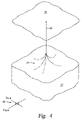
- FIG. 4 shows a hydrocarbon producing formation below a surface, and how the boreholes are drilled in accordance when not taking into account stress;
- FIG. 5 shows take points and/or injection points in the formation as in FIG. 4 , but with borehole trajectories for the take points and/or injection points selected in accordance with some embodiments;
- FIG. 6 shows a method in accordance with some embodiments.
- FIG. 7 shows a computer system in accordance with some embodiments.
- the terms “including” and “comprising” are used in an open-ended fashion, and thus should be interpreted to mean “including, but not limited to . . . ”.
- the term “couple” or “couples” is intended to mean either an indirect or direct connection. Thus, if a first device couples to a second device, that connection may be through a direct connection, or through an indirect connection via other devices and connections.
- the various embodiments of the invention are directed to methods and systems for determining take point placement (“producer wells”) and injector well placement (e.g., for secondary recovery using water injection), where the determination takes into account reservoir-wide stress and other reservoir characteristics not only at initial placement, but also over the life span of production from the formation.
- the various methods and systems take a holistic approach to producer well placement and completion, as well as a holistic approach to injector well placement and completion, to reduce cost, increase production (over prior placement methods), and/or to ensure financially viable production over the expected life of the field.
- the specification addresses individual considerations with the understanding that some or all of the individual considerations are considered in the holistic approach. The individual considerations begin with formation stress as it relates to injector well placement.
- the stress may have a prevailing component or direction, and thus may exhibit what is termed stress anisotropy.
- a particular unit volume of hydrocarbon formation may be under a “strike slip” stress tending to shear the unit volume of hydrocarbon formation in a horizontal plane. Formations tend to fracture more easily in the direction of the prevailing stress, and in accordance with some embodiments stress is taken into consideration when deciding injector well placement.
- FIG. 1 shows an injector well and producer well relative placement to illustrate the shortcomings of not taking the prevailing stress direction into account when planning relative placement of injector wells and producer wells.
- FIG. 1 illustrates three boreholes in a hydrocarbon formation: two injector well boreholes 12 and 14 ; and a producer well borehole 16 .
- all three boreholes reside in the same horizontal plane.
- the prevailing stress direction in this illustration is parallel to the horizontal plane, as shown by the coordinates 18 (Smax being the direction of prevailing stress, and 5 min being the direction of non-prevailing stress).
- Smax being the direction of prevailing stress
- 5 min being the direction of non-prevailing stress
- the formation tends to fracture in the direction of the producer well borehole 16 .
- Fracture of a formation increases the permeability in the direction of the fracture, and thus the physical distance of the water sweep towards the producer well borehole 16 from each of the injector well boreholes 12 and 14 will be greater than the physical distance of the water sweep perpendicular to the horizontal plane, as illustrated by arrows 17 and 19 .
- earlier water breakthrough at the producer well is likely.
- FIG. 2 illustrates an injector well and producer well placement in accordance with embodiments of the invention where relative placement takes into account the prevailing stress direction.
- FIG. 2 illustrates three boreholes in a hydrocarbon formation: two injector well boreholes 20 and 22 ; and a producer well borehole 24 .
- all three boreholes reside in the same horizontal plane; however, the prevailing stress direction in this illustration is perpendicular to the horizontal plane, as shown by the coordinates 26 .
- the formation tends to fracture perpendicularly to the horizontal plane. In other words, the formation tends to fracture perpendicular to the direction of the producer well borehole 24 .
- Fracture increases the permeability in the direction of the fracture, and thus the physical distance of the water sweep outward from each of the injector well boreholes 20 and 22 will be greater than the physical distance of the water sweep toward the producer well, as illustrated by arrows 27 and 29 .
- water breakthrough at the producer well is less likely (for the same center-to-center spacing of FIG. 1 ), and the water sweep toward the producer well borehole 24 has a greater vertical spread.
- the “sweeping” action of the secondary recovery using water injection is more efficient and the chance of water breakthrough is less likely because the fracture direction is perpendicular to the plane where the injector and producer boreholes reside.
- the prevailing stress direction is horizontal and vertical; however, horizontal and vertical prevailing stress directions are merely illustrative.
- the prevailing stress direction may be in any orientation, and thus one should not assume that having producer and injector wells in a horizontal plane is always the proper orientation. Having the producer and injector wells in the same horizontal plane would be the proper orientation if the prevailing stress direction was vertical.
- the prevailing stress direction of the formation should be substantially perpendicular to the plane.
- Underground faults may be tectonic in nature (e.g., the San Andreas fault that runs substantially through California), or the underground faults may be more localized. Regardless of scale, a fault represents and actual or potential geologic instability. Localized faults within or proximate to a hydrocarbon reservoir are in most cases inactive so long as there are no major physical changes to surrounding formations. However, in the presence of physical changes (e.g., reduced pressure on either side of the fault caused by hydrocarbon removal, an attempt to perform secondary recovery in the form of water injection where the water is forced across the fault), the localized fault may become active.
- the various embodiments of the invention take into account faults proximate to or within a hydrocarbon formation when determining the locations of producer wells and injector wells.
- injector well placement relative to producer well placement takes into account localized faults.
- injectors wells are positioned such that no faults exist between the injector wells and the one or more production wells toward which the injector well sweeps.
- the localized faults in a hydrocarbon formation may produce wildly varying stress regimes, and in accordance with embodiments of the invention the relative placement of producer wells and injector wells may vary over the formation.
- the injector wells may be physically above and below the producer wells toward which they sweep, yet in another portion of the formation the injector wells may reside within the same horizontal plane, all a function of stress in the formation caused by geologic shifts at the localized faults.
- producer well and injector well placement in accordance with embodiments of the invention takes into account not only the reservoir characteristics which dictate the best take point, but also takes into account the initial and time varying stress regime in the formation as well as local fault considerations.
- a completion is the physical interface between the borehole and the formation.
- Completions take many forms.
- the completion may be merely the borehole itself (no casing or liner).
- the completion may be a slotted casing to allow hydrocarbon flow into the casing, but with the casing still providing some structural support.
- a casing may be present with the casing perforated in particular directions in an attempt to increase hydrocarbon production from particular directions.
- the completion may be a gravel pack at the terminal end of the borehole.
- the completion may involve hydraulic fracturing of the formation surrounding the borehole, and in some case hydraulic insertion of a “propant” into the formation to help ensure continued permeability in spite of formation compaction. All these variations for completions may be applied in vertically oriented boreholes, high angle boreholes, or horizontal boreholes as the particular situation dictates.
- 7,181,380 discusses completion selection for producer wells, including considerations such as probable failure mechanisms (e.g., reservoir compaction, shear failure, fault re-activation and multi-phase hydrocarbon flow) and completion requirements (e.g., sand exclusion, sand avoidance, and deferred sand management). Stated otherwise, the aforementioned patent discusses considerations for choosing an optimum orientation and deviation (which together may be referred to as trajectory and/or direction), as well as choosing an optimum completion type for a producer well.
- probable failure mechanisms e.g., reservoir compaction, shear failure, fault re-activation and multi-phase hydrocarbon flow
- completion requirements e.g., sand exclusion, sand avoidance, and deferred sand management
- the injector wells in addition to making decisions regarding completion types for producer wells, similar decisions are made for the injector wells.
- failure mechanisms are not taken into account when choosing completion types for injector wells, and thus in most instances the least expensive completion is selected.
- the potential failure mechanism for producer wells that one may attempt to address based on the completion type also affect injector wells.
- the secondary considerations of sand management are also taken into account. In the case of an injector well, however the sand management concern is not production of sand, but rather formation plugging and reduced formation permeability caused by sand and other “fines” (fine grain materials).
- the injector well completion does not reduce or eliminate sand and fine production, the water injection through the injector well carries the sand and fines into the formation, which lodges and reduces permeability.
- the reduced permeability thus reduces the injected water's ability to migrate within the formation, and adversely affects sweep capability of the injector well.
- one or more of the various models e.g., reservoir model, geo-mechanical model, and material model
- the criteria discussed above are used to select the location, orientation, deviation and completion type for the injector wells which provide the lowest risk and highest return on investment for the overall reservoir over the life of the reservoir.
- FIG. 3 illustrates a plot of drilling risk 30 as a function of angle of the drilling direction relative to the prevailing stress direction (with drilling fluid weight, and therefore downhole pressure, held constant).
- the drilling risk of stress-induced borehole failures is at a maximum.
- the drilling risk of stress-induced borehole failures also drops, with the minimum risk of stress-induced borehole failure occurring when the drilling direction is perpendicular to the prevailing stress direction.
- the illustration of FIG. 3 assumes a two-dimension stress regime for purposes of simplified explanation. However, the idea of FIG.
- FIG. 3 scales to three-dimensional space, with drilling risk of stress-induced borehole failure being at a maximum in the three-dimensional prevailing stress direction.
- the discussion relative to FIG. 3 also assumes a constant drilling fluid weight; however, the risk of stress-induced borehole failures may also be tempered by increased drilling fluid weight (and therefore higher downhole pressure pushing against the walls).
- FIG. 3 shows the relationship between risk and drilling fluid weight by dashed line 32 .
- dashed line 32 illustrates the stress related risk with an increased drilling fluid weight.
- FIG. 4 illustrates a hydrocarbon formation 34 below a surface 36 , and which also illustrates how the boreholes are drilled in accordance with the related-art.
- a plurality of lateral boreholes 38 extend into the formation 34 at the pre-selected take points, and/or injection-points all branching from a single vertical borehole 40 centered above the formation 34 .
- the prevailing stress in the overburden formations (not specifically shown) is as illustrated by the coordinates 42 .
- the risk associated with the plurality of lateral boreholes 38 is higher, in some cases significantly higher, because of the historical momentum of placing the single vertical borehole 40 centered over the formation and drilling toward each take point and/or injection point. Moreover, selecting borehole trajectory in this manner does not take into account the optimum completion orientations, as discussed above.
- the boreholes to reach the take points and the injection points are engineered starting at the respective take points and injection points, with the engineering/route selection taking into account the preferred orientation of the completions as well as the prevailing stress in the overburden formation.
- Engineering boreholes and/or selecting routes for the boreholes in this manner dictates that in situations where the overburden formation has a prevailing stress direction, the drilling center may not correspond to the physical center of the formation. Rather, the drilling center may be shifted in the direction of the non-prevailing stress. While such a shift shortens some boreholes, it lengthens other boreholes; however, the drilling risk associate with substantially every borehole may be lowered because of the drilling direction relative to the direction of prevailing stress in the formations.
- FIG. 5 illustrates takes points and/or injection points in the formation as in FIG. 41 but in this case (and applying the various embodiments of the invention) the vertical borehole 42 is shifted in the non-prevailing stress direction, such that, as a whole, the lateral boreholes are drilled in such a manner as to reduce the risk of stress-induced borehole failure.
- FIG. 5 also illustrates that a preferred drilling direction (perpendicular to the prevailing stress), may not be the preferred completion orientation, and thus some drilling in a non-preferred direction is to be tolerated to accommodate particular completion orientations determined prior to drilling.
- the length of the boreholes drilled in the higher risk direction is reduced over the “spider web” approach of the related art, and the risk of drilling in the higher risk directions may be mitigated by careful control of drilling fluid weight, as discussed above.
- FIG. 6 illustrates a method in accordance with embodiments of the invention.
- FIG. 6 illustrates a method that ties together the individual considerations discussed above.
- the method starts (block 600 ) and moves to gathering data regarding a hydrocarbon formation and overburden formations (block 604 ).
- the data gather may be from seismic data, or data regarding nearby formations that are believed to be of similar character.
- a test or exploration well may be drilled into the hydrocarbon formation, and data may be gathered using logging while drilling, measuring while drilling, wireline tools, core samples, and the like.
- the data gathered may be data such as formation and overburden stress regimes, the presence and proximity of faults, formation porosity, rock strength and permeability.
- the method may be applied to an aging hydrocarbon formation whose production has fallen, and thus data of type discussed above may be readily available.
- the stress regime in the hydrocarbon formation and overburden is analyzed (block 608 ), and based at least in part on the analysis reservoir models and/or a geological models are built, with the models taking into account the initial stress regime and local and non-local faulting (block 612 ). From the one or more models, the time varying stress that can be expect to occur in the hydrocarbon formation is determined (block 616 ), possibly along with other reservoir characteristics (e.g., hydrocarbon capacity, expected production flow rate).
- reservoir characteristics e.g., hydrocarbon capacity, expected production flow rate
- the take points and injection points are selected (block 620 ).
- Take points are selected based on the models to achieve the most voluminous production and/or most efficient hydrocarbon removal from the hydrocarbon formation.
- injection points for secondary recovery are selected to achieve one or more of the most voluminous production and/or the most efficient hydrocarbon removal.
- the orientation, deviation and completion type for each take point and each injection point is determined (block 624 ).
- Copending and commonly assigned patent titled “System and process for optimal selection of hydrocarbon completion type and design,” discusses in detail the determination regarding orientation, deviation and completion type for take points.
- the same orientation, deviation and completion type determination is made with respect to injection points for secondary recovery.
- Other considerations that affect injection point placement are considered as well, such as the direction of the prevailing stress, and location of local faulting.
- the various borehole trajectories to reach the take points and injection points are engineered (block 628 ), taking into account stress in the formation and overburden, including placing the central borehole (if used) at a position off-center from the center of formation. Thereafter, the process ends (block 632 ).
- FIG. 7 illustrates a computer system suitable for implementing the various embodiments of the present invention.
- the computer system 700 comprises a processor 702 (also referred to as a central processing units, or CPU) that is coupled to memory devices such as primary storage devices 704 (e.g., a random access memory, or RAM) and primary storage devices 706 (e.g., a read only memory, or ROM).
- primary storage devices 704 e.g., a random access memory, or RAM
- primary storage devices 706 e.g., a read only memory, or ROM
- ROM acts to transfer data and instructions uni-directionally to the processor 702
- RAM is used to transfer data and instructions in a bi-directional manner.
- Both RAM 704 and ROM 706 may be considered computer-readable media.
- a secondary storage medium 708 e.g., mass memory device
- the mass memory device 708 may also be considered a computer-readable medium that may be used to store programs and data.
- Mass memory device 708 may be a storage medium such as a non-volatile memory (e.g., hard disk or a tape) which is in most cases has slower access times than RAM 704 and ROM 706 .
- a specific primary storage device 708 such as a CD-ROM may also pass data uni-directionally to the processor 702 .
- Processor 702 is also coupled to one or more input/output devices 710 (e.g., video monitors, track balls, mice, keyboards, microphones, touch-sensitive displays, transducer card readers, magnetic or paper tape readers, tablets, styluses, voice or handwriting recognizers, or other computers).
- processor may also coupled to a computer or telecommunications network using a network connection 712 .
- network connection 712 it is contemplated that processor may receive information from the network, or might output information to the network in the course of performing the process in accordance with the various embodiments. Such information, which is often represented as a sequence of instructions to be executed by processor 702 , may be received from and outputted to the network, for example, in the form of a computer data signal embodied in a carrier wave.
Landscapes
- Geology (AREA)
- Physics & Mathematics (AREA)
- Life Sciences & Earth Sciences (AREA)
- Engineering & Computer Science (AREA)
- Mining & Mineral Resources (AREA)
- Environmental & Geological Engineering (AREA)
- Geophysics (AREA)
- Fluid Mechanics (AREA)
- Geochemistry & Mineralogy (AREA)
- General Life Sciences & Earth Sciences (AREA)
- Consolidation Of Soil By Introduction Of Solidifying Substances Into Soil (AREA)
- Production Of Liquid Hydrocarbon Mixture For Refining Petroleum (AREA)
- Earth Drilling (AREA)
- Organic Low-Molecular-Weight Compounds And Preparation Thereof (AREA)
- Geophysics And Detection Of Objects (AREA)
Priority Applications (10)
| Application Number | Priority Date | Filing Date | Title |
|---|---|---|---|
| US11/464,551 US7657407B2 (en) | 2006-08-15 | 2006-08-15 | Method and system of planning hydrocarbon extraction from a hydrocarbon formation |
| CA2659372A CA2659372C (fr) | 2006-08-15 | 2007-08-14 | Procede et systeme pour concevoir une extraction d'hydrocarbures a partir d'une formation d'hydrocarbures |
| EP07814079.5A EP2052346B1 (fr) | 2006-08-15 | 2007-08-14 | Procédé et système pour concevoir une extraction d'hydrocarbures à partir d'une formation d'hydrocarbures |
| BRPI0715907-2A BRPI0715907A2 (pt) | 2006-08-15 | 2007-08-14 | mÉtodo para planejar extraÇço de hidrocarbonetos de uma formaÇço de hidrocarbonetos, meio legÍvel por computador, e, sistema de computador. |
| PCT/US2007/075897 WO2008022124A2 (fr) | 2006-08-15 | 2007-08-14 | Procédé et système pour concevoir une extraction d'hydrocarbures à partir d'une formation d'hydrocarbures |
| AU2007285948A AU2007285948B2 (en) | 2006-08-15 | 2007-08-14 | Method and system of planning hydrocarbon extraction from a hydrocarbon formation |
| CN200780030493.1A CN101512544B (zh) | 2006-08-15 | 2007-08-14 | 规划从含烃地层提取烃的方法和系统 |
| MX2009001425A MX2009001425A (es) | 2006-08-15 | 2007-08-14 | Metodo y sistema de planeacion para la extraccion de hidrocarburos de una formacion de hidrocarburos. |
| ARP070103618A AR062450A1 (es) | 2006-08-15 | 2007-08-15 | Metodo y sistema de planificacion para la extraccion de hidrocarburo de una formacion de hidrocarburo |
| NO20091092A NO340593B1 (no) | 2006-08-15 | 2009-03-12 | Fremgangsmåte og system for å planlegge hydrokarbonutvinning fra en hydrokarbonformasjon |
Applications Claiming Priority (1)
| Application Number | Priority Date | Filing Date | Title |
|---|---|---|---|
| US11/464,551 US7657407B2 (en) | 2006-08-15 | 2006-08-15 | Method and system of planning hydrocarbon extraction from a hydrocarbon formation |
Publications (2)
| Publication Number | Publication Date |
|---|---|
| US20080126050A1 US20080126050A1 (en) | 2008-05-29 |
| US7657407B2 true US7657407B2 (en) | 2010-02-02 |
Family
ID=39083057
Family Applications (1)
| Application Number | Title | Priority Date | Filing Date |
|---|---|---|---|
| US11/464,551 Active 2028-02-29 US7657407B2 (en) | 2006-08-15 | 2006-08-15 | Method and system of planning hydrocarbon extraction from a hydrocarbon formation |
Country Status (10)
| Country | Link |
|---|---|
| US (1) | US7657407B2 (fr) |
| EP (1) | EP2052346B1 (fr) |
| CN (1) | CN101512544B (fr) |
| AR (1) | AR062450A1 (fr) |
| AU (1) | AU2007285948B2 (fr) |
| BR (1) | BRPI0715907A2 (fr) |
| CA (1) | CA2659372C (fr) |
| MX (1) | MX2009001425A (fr) |
| NO (1) | NO340593B1 (fr) |
| WO (1) | WO2008022124A2 (fr) |
Cited By (12)
| Publication number | Priority date | Publication date | Assignee | Title |
|---|---|---|---|---|
| US20110172976A1 (en) * | 2008-10-01 | 2011-07-14 | Budiman Benny S | Robust Well Trajectory Planning |
| US8884964B2 (en) | 2008-04-22 | 2014-11-11 | Exxonmobil Upstream Research Company | Functional-based knowledge analysis in a 2D and 3D visual environment |
| US8931580B2 (en) | 2010-02-03 | 2015-01-13 | Exxonmobil Upstream Research Company | Method for using dynamic target region for well path/drill center optimization |
| US9026417B2 (en) | 2007-12-13 | 2015-05-05 | Exxonmobil Upstream Research Company | Iterative reservoir surveillance |
| US9223594B2 (en) | 2011-07-01 | 2015-12-29 | Exxonmobil Upstream Research Company | Plug-in installer framework |
| US9228393B2 (en) | 2011-03-08 | 2016-01-05 | Landmark Graphics Corporation | Method and system of drilling laterals in shale formations |
| US9595129B2 (en) | 2012-05-08 | 2017-03-14 | Exxonmobil Upstream Research Company | Canvas control for 3D data volume processing |
| US9593558B2 (en) | 2010-08-24 | 2017-03-14 | Exxonmobil Upstream Research Company | System and method for planning a well path |
| US9864098B2 (en) | 2013-09-30 | 2018-01-09 | Exxonmobil Upstream Research Company | Method and system of interactive drill center and well planning evaluation and optimization |
| US9874648B2 (en) | 2011-02-21 | 2018-01-23 | Exxonmobil Upstream Research Company | Reservoir connectivity analysis in a 3D earth model |
| US10318663B2 (en) | 2011-01-26 | 2019-06-11 | Exxonmobil Upstream Research Company | Method of reservoir compartment analysis using topological structure in 3D earth model |
| US10584570B2 (en) | 2013-06-10 | 2020-03-10 | Exxonmobil Upstream Research Company | Interactively planning a well site |
Families Citing this family (6)
| Publication number | Priority date | Publication date | Assignee | Title |
|---|---|---|---|---|
| US7529624B2 (en) * | 2007-02-21 | 2009-05-05 | Geomechanics International, Inc. | Method and apparatus for remote characterization of faults in the vicinity of boreholes |
| US10060245B2 (en) * | 2009-01-09 | 2018-08-28 | Halliburton Energy Services, Inc. | Systems and methods for planning well locations with dynamic production criteria |
| US20120271550A1 (en) * | 2009-11-02 | 2012-10-25 | Landmark Graphics Corporation | Seismic Imaging Systems and Methods Employing a 3D Reverse Time Migration with Tilted Transverse Isotropy |
| GB2479989A (en) * | 2010-04-26 | 2011-11-02 | Schlumberger Holdings | Optimizing a borehole trajectory based on a stress model |
| US8768671B2 (en) | 2010-04-26 | 2014-07-01 | Schlumberger Technology Corporation | System for optimizing a drilling operation and method for using same |
| CN109268005A (zh) * | 2018-10-30 | 2019-01-25 | 中国石油大学(华东) | 一种基于储层时变性的剩余油预测方法及工业化流程 |
Citations (5)
| Publication number | Priority date | Publication date | Assignee | Title |
|---|---|---|---|---|
| US20020072883A1 (en) * | 2000-06-29 | 2002-06-13 | Kok-Thye Lim | Method and system for high-resolution modeling of a well bore in a hydrocarbon reservoir |
| US20040122640A1 (en) | 2002-12-20 | 2004-06-24 | Dusterhoft Ronald G. | System and process for optimal selection of hydrocarbon well completion type and design |
| US7042802B2 (en) * | 2003-09-18 | 2006-05-09 | Schlumberger Technology Corporation | Determination of stress characteristics of earth formations |
| US20060118305A1 (en) * | 2004-12-02 | 2006-06-08 | East Loyd E Jr | Hydrocarbon sweep into horizontal transverse fractured wells |
| US20070209799A1 (en) * | 2001-10-24 | 2007-09-13 | Shell Oil Company | In situ recovery from a hydrocarbon containing formation |
Family Cites Families (3)
| Publication number | Priority date | Publication date | Assignee | Title |
|---|---|---|---|---|
| GB2354852B (en) * | 1999-10-01 | 2001-11-28 | Schlumberger Holdings | Method for updating an earth model using measurements gathered during borehole construction |
| US7630914B2 (en) * | 2004-03-17 | 2009-12-08 | Schlumberger Technology Corporation | Method and apparatus and program storage device adapted for visualization of qualitative and quantitative risk assessment based on technical wellbore design and earth properties |
| CN1594829A (zh) * | 2004-06-18 | 2005-03-16 | 大庆油田有限责任公司 | 预防油田套管损坏的方法 |
-
2006
- 2006-08-15 US US11/464,551 patent/US7657407B2/en active Active
-
2007
- 2007-08-14 EP EP07814079.5A patent/EP2052346B1/fr not_active Ceased
- 2007-08-14 AU AU2007285948A patent/AU2007285948B2/en not_active Ceased
- 2007-08-14 WO PCT/US2007/075897 patent/WO2008022124A2/fr not_active Ceased
- 2007-08-14 BR BRPI0715907-2A patent/BRPI0715907A2/pt not_active IP Right Cessation
- 2007-08-14 MX MX2009001425A patent/MX2009001425A/es active IP Right Grant
- 2007-08-14 CN CN200780030493.1A patent/CN101512544B/zh not_active Expired - Fee Related
- 2007-08-14 CA CA2659372A patent/CA2659372C/fr active Active
- 2007-08-15 AR ARP070103618A patent/AR062450A1/es not_active Application Discontinuation
-
2009
- 2009-03-12 NO NO20091092A patent/NO340593B1/no unknown
Patent Citations (5)
| Publication number | Priority date | Publication date | Assignee | Title |
|---|---|---|---|---|
| US20020072883A1 (en) * | 2000-06-29 | 2002-06-13 | Kok-Thye Lim | Method and system for high-resolution modeling of a well bore in a hydrocarbon reservoir |
| US20070209799A1 (en) * | 2001-10-24 | 2007-09-13 | Shell Oil Company | In situ recovery from a hydrocarbon containing formation |
| US20040122640A1 (en) | 2002-12-20 | 2004-06-24 | Dusterhoft Ronald G. | System and process for optimal selection of hydrocarbon well completion type and design |
| US7042802B2 (en) * | 2003-09-18 | 2006-05-09 | Schlumberger Technology Corporation | Determination of stress characteristics of earth formations |
| US20060118305A1 (en) * | 2004-12-02 | 2006-06-08 | East Loyd E Jr | Hydrocarbon sweep into horizontal transverse fractured wells |
Non-Patent Citations (2)
| Title |
|---|
| P. Macini, et al. Casing Influence While Measuring in Situ Reservoir Compaction-Journal of Petroleum Science & Engineering 50 (2006) 40-54-Bologna, Italy. |
| PCT International Search Report and Written Opinion-Dated Sep. 16, 2008. |
Cited By (13)
| Publication number | Priority date | Publication date | Assignee | Title |
|---|---|---|---|---|
| US9026417B2 (en) | 2007-12-13 | 2015-05-05 | Exxonmobil Upstream Research Company | Iterative reservoir surveillance |
| US8884964B2 (en) | 2008-04-22 | 2014-11-11 | Exxonmobil Upstream Research Company | Functional-based knowledge analysis in a 2D and 3D visual environment |
| US8892407B2 (en) | 2008-10-01 | 2014-11-18 | Exxonmobil Upstream Research Company | Robust well trajectory planning |
| US20110172976A1 (en) * | 2008-10-01 | 2011-07-14 | Budiman Benny S | Robust Well Trajectory Planning |
| US8931580B2 (en) | 2010-02-03 | 2015-01-13 | Exxonmobil Upstream Research Company | Method for using dynamic target region for well path/drill center optimization |
| US9593558B2 (en) | 2010-08-24 | 2017-03-14 | Exxonmobil Upstream Research Company | System and method for planning a well path |
| US10318663B2 (en) | 2011-01-26 | 2019-06-11 | Exxonmobil Upstream Research Company | Method of reservoir compartment analysis using topological structure in 3D earth model |
| US9874648B2 (en) | 2011-02-21 | 2018-01-23 | Exxonmobil Upstream Research Company | Reservoir connectivity analysis in a 3D earth model |
| US9228393B2 (en) | 2011-03-08 | 2016-01-05 | Landmark Graphics Corporation | Method and system of drilling laterals in shale formations |
| US9223594B2 (en) | 2011-07-01 | 2015-12-29 | Exxonmobil Upstream Research Company | Plug-in installer framework |
| US9595129B2 (en) | 2012-05-08 | 2017-03-14 | Exxonmobil Upstream Research Company | Canvas control for 3D data volume processing |
| US10584570B2 (en) | 2013-06-10 | 2020-03-10 | Exxonmobil Upstream Research Company | Interactively planning a well site |
| US9864098B2 (en) | 2013-09-30 | 2018-01-09 | Exxonmobil Upstream Research Company | Method and system of interactive drill center and well planning evaluation and optimization |
Also Published As
| Publication number | Publication date |
|---|---|
| NO340593B1 (no) | 2017-05-15 |
| CN101512544A (zh) | 2009-08-19 |
| WO2008022124A3 (fr) | 2008-11-13 |
| AU2007285948A1 (en) | 2008-02-21 |
| AR062450A1 (es) | 2008-11-12 |
| EP2052346A2 (fr) | 2009-04-29 |
| CA2659372A1 (fr) | 2008-02-21 |
| BRPI0715907A2 (pt) | 2013-09-03 |
| EP2052346A4 (fr) | 2014-10-15 |
| EP2052346B1 (fr) | 2017-01-11 |
| NO20091092L (no) | 2009-05-11 |
| MX2009001425A (es) | 2009-03-13 |
| WO2008022124A2 (fr) | 2008-02-21 |
| CA2659372C (fr) | 2011-11-22 |
| CN101512544B (zh) | 2015-11-25 |
| US20080126050A1 (en) | 2008-05-29 |
| AU2007285948B2 (en) | 2011-01-20 |
Similar Documents
| Publication | Publication Date | Title |
|---|---|---|
| CA2659372C (fr) | Procede et systeme pour concevoir une extraction d'hydrocarbures a partir d'une formation d'hydrocarbures | |
| Al-Jubori et al. | Coalbed methane: clean energy for the world | |
| Gakhar et al. | Engineering an effective completion and stimulation strategy for in-fill wells | |
| US7967069B2 (en) | Active seismic monitoring of fracturing operations | |
| Khlaifat et al. | Tight gas sands development is critical to future world energy resources | |
| Kennedy et al. | Comparisons and contrasts of shale gas and tight gas developments, North American experience and trends | |
| Qian et al. | Diagnostics of casing deformation in multi-stage hydraulic fracturing stimulation in lower Silurian marine shale play in Southwestern China | |
| Tian et al. | Coalbed methane reservoir fracture evaluation through the novel passive microseismic survey and its implications on permeable and gas production | |
| CN113494284A (zh) | 深层页岩气储层水力压裂参数确定方法、装置和存储介质 | |
| Romanson et al. | Novel, multistage stimulation processes can help achieve and control branch fracturing and increase stimulated reservoir volume for unconventional reservoirs | |
| Khlaifat | Unconventional Gas is the Fuel of the Future for Jordan | |
| Dahmane et al. | Integrated Fractured Reservoir Modeling and Secondary Oil Recovery Techniques: A Historical Case Study for Productivity Improvement in the Chinguetti Offshore Oil Reservoir in the Coastal Basin of Mauritania | |
| Ueda et al. | A fully integrated approach for screening of well completion and stimulation methods in low permeability, heterogeneously distributed sandstone reservoirs in the deepwater slope channel, Kita-Akita oil field, Northern Japan | |
| Astafyev et al. | Multistage hydrocarbon-based fracturing in tight gas formation | |
| Yilmaz et al. | An Iterative Approach to Enhance Frac Design and Economics While Developing Tight Gas Reservoirs | |
| Izurieta et al. | Hydraulic Fracturing Evolution in Block 61: TSO, Channel Fracturing and Waterflooding | |
| Ashqar et al. | An Engineered Workflow to Optimize an Openhole Multistage Acid Frac Design in Unconventional Horizontal Wells in North Kuwait | |
| Al-Saedi et al. | A Novel Fishbone Hydraulic Fracturing Technique for Tight Carbonate Reservoirs in Iraq: A Comparative Numerical Study with Traditional Stimulation Method | |
| Kilicaslan et al. | Fracturing and Production Characteristics of Tight Gas Reservoir: A Case Study from Thrace Basin, Turkey | |
| Ashena et al. | Successful Revival of Well Production Using Radial Jet Drilling in a Water-Conning Case Study | |
| John Pallikathekathil et al. | A Multidisciplinary Approach in Understanding the Challenges in Drilling Infill Extended-Reach Wells in the Depleted Stag Field, Northwest Shelf, Australia—A Case Study | |
| Al Aamri et al. | Setting a New Benchmark in Tight Gas Hydraulic Fracturing: Integrated Workflow for Optimized Design, Execution, and Production from the First Horizontal Well in the M Formation in Sultanate of Oman | |
| Parfenov et al. | Particularities of hydraulic fracturing in dome type reservoirs of Samara Area in the Volga-Urals Basin | |
| Reina et al. | Successful Implementation CO2 Assisted Hydraulic Fracturing in a Deep and Low Permeability Sandstone Reservoir: First Case in Colombia | |
| Xiaoguang et al. | Integrated approach for improving development of a Mature Field |
Legal Events
| Date | Code | Title | Description |
|---|---|---|---|
| AS | Assignment |
Owner name: LANDMARK GRAPHICS CORPORATION, TEXAS Free format text: ASSIGNMENT OF ASSIGNORS INTEREST;ASSIGNOR:LOGAN, RICHARD B;REEL/FRAME:018107/0615 Effective date: 20060814 Owner name: LANDMARK GRAPHICS CORPORATION,TEXAS Free format text: ASSIGNMENT OF ASSIGNORS INTEREST;ASSIGNOR:LOGAN, RICHARD B;REEL/FRAME:018107/0615 Effective date: 20060814 |
|
| STCF | Information on status: patent grant |
Free format text: PATENTED CASE |
|
| FPAY | Fee payment |
Year of fee payment: 4 |
|
| FPAY | Fee payment |
Year of fee payment: 8 |
|
| MAFP | Maintenance fee payment |
Free format text: PAYMENT OF MAINTENANCE FEE, 12TH YEAR, LARGE ENTITY (ORIGINAL EVENT CODE: M1553); ENTITY STATUS OF PATENT OWNER: LARGE ENTITY Year of fee payment: 12 |