US7690190B2 - Aircraft systems including cascade thrust reversers - Google Patents
Aircraft systems including cascade thrust reversers Download PDFInfo
- Publication number
- US7690190B2 US7690190B2 US11/127,424 US12742405A US7690190B2 US 7690190 B2 US7690190 B2 US 7690190B2 US 12742405 A US12742405 A US 12742405A US 7690190 B2 US7690190 B2 US 7690190B2
- Authority
- US
- United States
- Prior art keywords
- wall section
- nozzle outer
- slope
- reverser
- section
- Prior art date
- Legal status (The legal status is an assumption and is not a legal conclusion. Google has not performed a legal analysis and makes no representation as to the accuracy of the status listed.)
- Active, expires
Links
- 230000008901 benefit Effects 0.000 description 5
- 230000009467 reduction Effects 0.000 description 3
- 230000007704 transition Effects 0.000 description 3
- 230000002411 adverse Effects 0.000 description 1
- 230000008859 change Effects 0.000 description 1
- 230000000694 effects Effects 0.000 description 1
- 230000004048 modification Effects 0.000 description 1
- 238000012986 modification Methods 0.000 description 1
Images



Classifications
-
- F—MECHANICAL ENGINEERING; LIGHTING; HEATING; WEAPONS; BLASTING
- F02—COMBUSTION ENGINES; HOT-GAS OR COMBUSTION-PRODUCT ENGINE PLANTS
- F02K—JET-PROPULSION PLANTS
- F02K1/00—Plants characterised by the form or arrangement of the jet pipe or nozzle; Jet pipes or nozzles peculiar thereto
- F02K1/54—Nozzles having means for reversing jet thrust
- F02K1/64—Reversing fan flow
-
- F—MECHANICAL ENGINEERING; LIGHTING; HEATING; WEAPONS; BLASTING
- F02—COMBUSTION ENGINES; HOT-GAS OR COMBUSTION-PRODUCT ENGINE PLANTS
- F02K—JET-PROPULSION PLANTS
- F02K1/00—Plants characterised by the form or arrangement of the jet pipe or nozzle; Jet pipes or nozzles peculiar thereto
- F02K1/54—Nozzles having means for reversing jet thrust
- F02K1/64—Reversing fan flow
- F02K1/70—Reversing fan flow using thrust reverser flaps or doors mounted on the fan housing
- F02K1/72—Reversing fan flow using thrust reverser flaps or doors mounted on the fan housing the aft end of the fan housing being movable to uncover openings in the fan housing for the reversed flow
-
- Y—GENERAL TAGGING OF NEW TECHNOLOGICAL DEVELOPMENTS; GENERAL TAGGING OF CROSS-SECTIONAL TECHNOLOGIES SPANNING OVER SEVERAL SECTIONS OF THE IPC; TECHNICAL SUBJECTS COVERED BY FORMER USPC CROSS-REFERENCE ART COLLECTIONS [XRACs] AND DIGESTS
- Y02—TECHNOLOGIES OR APPLICATIONS FOR MITIGATION OR ADAPTATION AGAINST CLIMATE CHANGE
- Y02T—CLIMATE CHANGE MITIGATION TECHNOLOGIES RELATED TO TRANSPORTATION
- Y02T50/00—Aeronautics or air transport
- Y02T50/60—Efficient propulsion technologies, e.g. for aircraft
Definitions
- the present invention is related to aircraft systems having cascade thrust reversers.
- Jet aircraft such as commercial passenger and military aircraft, include nacelles for housing the jet engines.
- the nacelles couple the engines to the wings and include thrust reversers to reduce the aircraft's speed after landing.
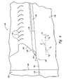
- FIG. 1 is a schematic illustration of a section of an aft portion of a conventional nacelle 10 .
- the nacelle 10 includes a fan casing 20 and a thrust reverser 30 aft of the fan casing 20 .
- the fan casing 20 has a nozzle outer wall section 22 and a nozzle inner wall section 24 positioned radially inward of the outer wall section 22 .
- the thrust reverser 30 includes a nozzle outer wall section 40 and a nozzle inner wall section 50 positioned radially inward of the outer wall section 40 .
- the nozzle outer wall sections 22 and 40 and the nozzle inner wall sections 24 and 50 of the fan casing 20 and thrust reverser 30 define a nozzle 58 through which fan gas flows to produce forward thrust.
- the nozzle outer wall section 40 in the thrust reverser 30 includes a forward portion 42 with a leading edge section 44 and a blocker door 46 .
- the blocker door 46 is movable between a stowed position (shown in FIG. 1 ) and a deployed position.
- the conventional thrust reverser 30 further includes a translating cowling 32 coupled to the nozzle outer wall section 40 and a plurality of guide vanes 70 positioned operably between the translating cowling 32 and the nozzle outer wall section 40 .
- the translating cowling 32 and the nozzle outer wall section 40 are movable as a unit between a stowed position (shown in FIG. 1 ) and a deployed position. In the deployed position, the cowling 32 and the outer wall section 40 are positioned aft of the guide vanes 70 so that the guide vanes 70 are exposed to gas flow in the nozzle 58 and the ambient environment.
- the blocker door 46 obstructs gas flow through the nozzle 58 so that at least a portion of the flow is diverted radially outward through the guide vanes 70 .
- fan gas flows through the nozzle 58 to produce forward thrust.
- the nozzle outer wall section 22 of the fan casing 20 and the nozzle outer wall section 40 of the thrust reverser 30 form a generally smooth flow line and aerodynamically continuous surface to maximize the forward thrust produced by the engine.
- the leading edge section 44 and/or the forward portion 42 of the nozzle outer wall section 40 is generally aligned with and parallel to the nozzle outer wall section 22 when the nozzle outer wall section 40 is in the stowed position.
- An aircraft system in accordance with one embodiment includes a cascade thrust reverser having a fixed reverser ramp and a nozzle outer wall section at least partially aft of the fixed reverser ramp.
- the nozzle outer wall section is movable between a deployed position and a stowed position.
- the nozzle outer wall section includes a forward portion with a leading edge section.
- the fixed reverser ramp has a portion forward of and adjacent to the nozzle outer wall section when the nozzle outer wall section is in the stowed position.
- the portion of the fixed reverser ramp has a first slope.
- the forward portion of the nozzle outer wall section that is aft of the leading edge section has a second slope different than the first slope.
- the leading edge section of the nozzle outer wall section has a third slope that can be generally the same as or different than the first slope.
- the forward portion of the nozzle outer wall section and the fixed reverser ramp define a pit that generates excrescence in the nozzle.
- the aircraft system further includes a wing coupled to the thrust reverser, a fuselage attached to the wing, and a tail coupled to the fuselage.
- an aircraft system in another embodiment, includes a thrust reverser and a fan casing coupled to the thrust reverser.
- the thrust reverser includes a nozzle outer wall section configured to move between a first position and a second position aft of the first position.
- the nozzle outer wall section includes a forward portion with a first slope along an axis.
- the fan casing includes a nozzle outer wall section having an aft portion with a second slope along the axis. The first slope is different than the second slope.
- the forward portion of the nozzle outer wall section in the thrust reverser includes a leading edge
- the thrust reverser further includes a fixed reverser ramp having a portion forward of and adjacent to the leading edge.
- the portion of the fixed reverser ramp has a third slope different than the first slope when the nozzle outer wall section is in the first position.
- the fixed reverser ramp includes a forward section in the fan casing or the thrust reverser and an aft section in the thrust reverser.
- an aircraft system in another embodiment, includes a thrust reverser having a fixed reverser ramp and a nozzle outer wall section at least partially aft of the fixed reverser ramp.
- the nozzle outer wall section is movable between a deployed position and a stowed position.
- the nozzle outer wall section includes a forward portion with a leading edge section. When the nozzle outer wall section is in the stowed position, the forward portion of the nozzle outer wall section is positioned such that a forward axial projection of the forward portion intersects the fixed reverser ramp non-tangentially.
- FIG. 1 is a schematic illustration of a section of a conventional nacelle.
- FIG. 2 is a schematic isometric view of an aircraft having a plurality of power plants in accordance with one embodiment of the invention.
- FIG. 3 is a schematic view of a portion of the power plant of FIG. 2 .
- FIG. 4 is an enlarged schematic view of a forward portion of a nozzle outer wall section in the power plant of FIG. 2 .
- FIG. 5 is a schematic enlarged view of a portion of a power plant in accordance with another embodiment of the invention.
- FIG. 2 is a schematic isometric view of an aircraft 100 having a plurality of power plants 110 in accordance with one embodiment of the invention.
- the aircraft 100 further includes a fuselage 102 , a plurality of wings 104 attached to the fuselage 102 , and a tail 106 attached to the fuselage 102 .
- the illustrated power plants 110 are mounted to corresponding wings 104 , in other embodiments, the power plants 110 can be coupled to the fuselage 102 and/or the tail 106 .
- the individual power plants 110 include an inlet housing 118 , a fan casing 120 coupled to the inlet housing 118 , and a thrust reverser 130 coupled to the fan casing 120 .
- FIG. 3 is a schematic view of a portion of one of the power plants 110 illustrated in FIG. 2 .
- the illustrated fan casing 120 includes a nozzle outer wall section 122 and a nozzle inner wall section 124 positioned radially inward of the outer wall section 122 .
- the illustrated thrust reverser 130 includes a nozzle outer wall section 140 and a nozzle inner wall section 150 positioned radially inward of the outer wall section 140 .
- the nozzle outer wall sections 122 and 140 and the nozzle inner wall sections 124 and 150 of the fan casing 120 and thrust reverser 130 define a nozzle 158 through which fan gas flows in a direction F to produce forward thrust for the power plant 110 .
- the nozzle 158 is positioned radially outward from an axis of symmetry A of the power plant 110 .
- the illustrated nozzle outer wall section 140 is spaced radially outward and aft relative to conventional thrust reverser nozzle outer wall sections. Consequently, the area of the nozzle 158 between the thrust reverser nozzle outer and inner wall sections 140 and 150 is greater than the corresponding area in conventional thrust reversers.
- the thrust reverser nozzle outer wall section 140 has a forward portion 142 with a leading edge section 144 and a blocker door 146 .
- the blocker door 146 is movable between a stowed position (shown in solid lines) and a deployed position (shown in broken lines).
- the illustrated thrust reverser 130 further includes a translating cowling 132 coupled to the nozzle outer wall section 140 and a plurality of guide vanes 170 positioned between the translating cowling 132 and the nozzle outer wall section 140 .
- the translating cowling 132 and the nozzle outer wall section 140 are movable as a unit between a stowed position (shown in solid lines) and a deployed position (shown in broken lines).
- the nozzle outer wall section 140 and the blocker door 146 When the nozzle outer wall section 140 and the blocker door 146 are in the stowed position, the nozzle outer wall section 140 directs gas aftward to produce forward thrust.
- the guide vanes 170 When the translating cowling 132 , the nozzle outer wall section 140 , and the blocker door 146 are in the deployed position, the guide vanes 170 are exposed to gas flow in the nozzle 158 and the blocker door 146 obstructs gas flow through the nozzle 158 so that at least a portion of the flow is diverted radially outward through the guide vanes 170 .
- the guide vanes 170 change the direction of the gas flow to generate reverse thrust to assist in decelerating the aircraft 100 ( FIG. 2 ).
- the illustrated thrust reverser 130 has an aft blocker door configuration, in other embodiments, the thrust reverser may include a forward blocker door configuration.
- FIG. 4 is an enlarged schematic view of the forward portion 142 of the nozzle outer wall section 140 of FIG. 3 .
- the forward portion 142 aft of the leading edge section 144 has an inner surface contour with a first slope S 1
- the leading edge section 144 has an inner surface contour with a second slope S 2 the same as the first slope S 1 .
- the leading edge section 144 can have an inner surface contour with a slope that is not the same as the first slope S 1 .
- the illustrated nozzle outer wall section 122 of the fan casing 120 has an inner surface contour with a third slope S 3 different than the first slope S 1 and oriented at an angle ⁇ relative to the first slope S 1 of the forward portion 142 when the thrust reverser nozzle outer wall section 140 is in the stowed position.
- the thrust reverser nozzle outer wall section 140 and fan casing nozzle outer wall section 122 can be configured such that the first slope S 1 is generally the same as the third slope S 3 .
- the illustrated thrust reverser 130 further includes a bullnose fairing or fixed thrust reversers ramp 160 extending aftwardly and radially outwardly from the nozzle outer wall section 122 of the fan casing 120 toward the guide vanes 170 .
- the thrust reverser ramp 160 has a forward portion 162 and an aft portion 164 .
- the forward portion 162 forms an integral portion of the nozzle 158 , and consequently, is exposed to fan gas flow through the nozzle 158 when the nozzle outer wall section 140 is in the stowed position.
- the aft portion 164 is exposed to fan gas flow when the nozzle outer wall section 140 is in the deployed position and at least a portion of the flow is directed radially outward through the guide vanes 170 .
- a point A at which the nozzle outer wall section 140 would intersect the thrust reverse ramp 160 if the inner surface of the nozzle outer wall section 140 were projected forward along the first slope S 1 , divides the thrust reverser ramp 160 into the forward portion 162 and the aft portion 164 .
- the forward portion 162 has an inner surface contour with a fourth slope S 4 at the point A that is oriented at an angle ⁇ and generally transverse to the first slope S 1 of the thrust reverser nozzle outer wall section 140 .
- the forward portion 162 of the fixed thrust reverser ramp 160 and the forward portion 142 of the nozzle outer wall section 140 define a pit 180 , which can generate excrescence in the nozzle 158 .
- the transition between the fan casing nozzle outer wall section 122 and the forward portion 142 of the thrust reverser nozzle outer wall section 140 is at least partially aerodynamically discontinuous.
- the forward section of the illustrated thrust reverser ramp 160 is positioned at an interface 128 between the thrust reverser 130 and the fan casing 120 , in other embodiments, the forward section of the thrust reverser ramp 160 can be positioned within the fan casing 120 or aft of the interface 128 .
- one feature of the illustrated thrust reverser 130 is that the thrust reverser nozzle outer wall section 140 (when in the stowed position) is spaced aft and radially outward relative to the corresponding walls in conventional thrust reversers. Because the thrust reverser nozzle outer wall section 140 is spaced aft relative to conventional walls, a stroke or distance D 1 between the deployed and stowed positions of the illustrated outer wall section 140 is less than the stroke of conventional walls.
- An advantage of the reduced stroke of the nozzle outer wall section 140 is that smaller actuators and tracks for moving the wall section 140 between the deployed and stowed positions can be used. For example, in several embodiments, the length of the tracks can be reduced by between one and two inches.
- the length of the tracks can be reduced by less than one inch or more than two inches. In either case, reducing the size of the actuators and tracks reduces the weight and space required to house these components in the power plant 110 .
- the power plant 110 may utilize a smaller size fairing for enclosing the tracks. The reduction in the weight and size of these components increases the performance of the power plant 110 .
- the spacing of the illustrated thrust reverser nozzle outer wall section 140 radially outward relative to corresponding walls in conventional thrust reversers increases a distance D 2 between the nozzle outer wall section 140 and the nozzle inner wall section 150 , which increases the area of the nozzle 158 between the nozzle outer and inner wall sections 140 and 150 .
- the increased area of the nozzle 158 reduces the velocity of the gas flowing through the nozzle 158 , which in turn, reduces the losses in the gas flow due to skin friction along the nozzle outer and inner wall sections 140 and 150 .
- the inventors expect that the losses due to the aerodynamic discontinuity at the transition between the fan casing nozzle outer wall section 122 and the forward portion 142 of the thrust reverser nozzle outer wall section 140 are offset by the reduction in the skin friction of the gas flowing through the nozzle 158 .
- the losses caused by the flow of the gas around the forward portion 162 of the fixed thrust reverser ramp 160 and through the pit 180 are generally offset by the reduction in the skin friction of the gas flowing through the nozzle 158 .
- the illustrated thrust reverser 130 reduces the weight of the power plant 110 without a significant adverse effect on the thrust.
- FIG. 5 is a schematic enlarged view of a portion of a power plant 210 configured in accordance with another embodiment of the invention.
- the illustrated power plant 210 includes a thrust reverser 230 generally similar to the thrust reverser 130 described above with reference to FIGS. 3 and 4 .
- the illustrated thrust reverser 230 includes a nozzle outer wall section 240 having a forward portion 242 with an arcuate leading edge section 244 .
- the forward portion 242 has an inner surface contour with a first slope S 1 aft of the leading edge section 244
- the leading edge section 244 has an inner surface contour with a fifth slope S 5 oriented at an angle ⁇ generally transverse to the first slope S 1 .
- the arcuate leading edge section 244 projects forwardly and radially outwardly and defines, along with the fixed thrust reverser ramp 160 , a pit 280 .
- One advantage of the illustrated thrust reverser 230 is that the curvature of the leading edge section 244 allows the nozzle outer wall section 240 to be spaced aft and radially outward relative to corresponding walls in conventional thrust reversers.
Landscapes
- Engineering & Computer Science (AREA)
- Chemical & Material Sciences (AREA)
- Combustion & Propulsion (AREA)
- Mechanical Engineering (AREA)
- General Engineering & Computer Science (AREA)
- Structures Of Non-Positive Displacement Pumps (AREA)
- Tires In General (AREA)
Priority Applications (3)
| Application Number | Priority Date | Filing Date | Title |
|---|---|---|---|
| US11/127,424 US7690190B2 (en) | 2005-05-11 | 2005-05-11 | Aircraft systems including cascade thrust reversers |
| ES06008143.7T ES2523885T3 (es) | 2005-05-11 | 2006-04-20 | Sistema de inversor de empuje para una aeronave |
| EP06008143.7A EP1726812B1 (de) | 2005-05-11 | 2006-04-20 | Schubumkehrsystem für ein Flugzeug |
Applications Claiming Priority (1)
| Application Number | Priority Date | Filing Date | Title |
|---|---|---|---|
| US11/127,424 US7690190B2 (en) | 2005-05-11 | 2005-05-11 | Aircraft systems including cascade thrust reversers |
Publications (2)
| Publication Number | Publication Date |
|---|---|
| US20060277895A1 US20060277895A1 (en) | 2006-12-14 |
| US7690190B2 true US7690190B2 (en) | 2010-04-06 |
Family
ID=37056861
Family Applications (1)
| Application Number | Title | Priority Date | Filing Date |
|---|---|---|---|
| US11/127,424 Active 2027-11-07 US7690190B2 (en) | 2005-05-11 | 2005-05-11 | Aircraft systems including cascade thrust reversers |
Country Status (3)
| Country | Link |
|---|---|
| US (1) | US7690190B2 (de) |
| EP (1) | EP1726812B1 (de) |
| ES (1) | ES2523885T3 (de) |
Cited By (9)
| Publication number | Priority date | Publication date | Assignee | Title |
|---|---|---|---|---|
| US20090326783A1 (en) * | 2008-06-30 | 2009-12-31 | Honeywell International Inc. | Fluid-powered thrust reverser actuation system speed control |
| US20130277454A1 (en) * | 2010-10-04 | 2013-10-24 | Snecma | Aircraft propulsion assembly |
| US8713911B2 (en) | 2010-12-15 | 2014-05-06 | Woodward Hrt, Inc. | System and method for operating a thrust reverser for a turbofan propulsion system |
| US9611808B2 (en) | 2014-03-21 | 2017-04-04 | Rohr, Inc. | Blocker door lock mechanism of a thrust reverser for a turbofan engine |
| US9739235B2 (en) | 2014-03-21 | 2017-08-22 | Rohr, Inc. | Thrust reverser for a turbofan engine |
| US9938929B2 (en) | 2014-03-21 | 2018-04-10 | Rohr, Inc. | Thrust reverser for a turbofan engine |
| US9976516B2 (en) | 2014-03-21 | 2018-05-22 | Rohr, Inc. | Thrust reverser for a turbofan engine |
| US10066510B2 (en) | 2013-03-15 | 2018-09-04 | United Technologies Corporation | Nacelle mounted latching system |
| US11802523B2 (en) | 2020-12-12 | 2023-10-31 | Rohr, Inc. | Multi-lobed bullnose ramp |
Families Citing this family (9)
| Publication number | Priority date | Publication date | Assignee | Title |
|---|---|---|---|---|
| US20110101158A1 (en) * | 2005-03-29 | 2011-05-05 | The Boeing Company | Thrust Reversers Including Monolithic Components |
| US7559507B2 (en) * | 2005-06-27 | 2009-07-14 | The Boeing Company | Thrust reversers including locking assemblies for inhibiting deflection |
| US7600371B2 (en) | 2005-10-18 | 2009-10-13 | The Boeing Company | Thrust reversers including support members for inhibiting deflection |
| US8201390B2 (en) * | 2007-12-12 | 2012-06-19 | Spirit Aerosystems, Inc. | Partial cascade thrust reverser |
| US8109466B2 (en) * | 2008-06-23 | 2012-02-07 | Rohr, Inc. | Thrust reverser cascade assembly and AFT cascade ring with flow deflector portion |
| FR2961555B1 (fr) * | 2010-06-18 | 2014-04-18 | Aircelle Sa | Structure de redressement de flux d'air pour nacelle de moteur d'aeronef |
| US9086034B2 (en) | 2011-10-13 | 2015-07-21 | Rohr, Inc. | Thrust reverser cascade assembly with flow deflection shelf |
| EP3047133A4 (de) * | 2013-09-19 | 2017-05-10 | United Technologies Corporation | Erweiterte schubumkehrerkaskade |
| US11208970B2 (en) * | 2018-06-28 | 2021-12-28 | Rohr, Inc. | Aft cascade ring design concept |
Citations (72)
| Publication number | Priority date | Publication date | Assignee | Title |
|---|---|---|---|---|
| US3500644A (en) | 1968-04-10 | 1970-03-17 | Rohr Corp | Thrust reverser |
| US3600023A (en) | 1970-02-09 | 1971-08-17 | Rohr Corp | Locking system |
| US3762667A (en) | 1971-12-29 | 1973-10-02 | D Pender | Vertical take-off and landing aircraft |
| US3824785A (en) | 1971-12-07 | 1974-07-23 | Moteurs D Aviat Soc Nat Et Con | Gas turbine ducted fan engines |
| US4044973A (en) | 1975-12-29 | 1977-08-30 | The Boeing Company | Nacelle assembly and mounting structures for a turbofan jet propulsion engine |
| US4283028A (en) | 1979-12-03 | 1981-08-11 | The Boeing Company | Adjustable wedge fitting for sharing the thrust load of a jet engine |
| US4286727A (en) | 1980-08-19 | 1981-09-01 | United Technologies Corporation | Tank cap |
| US4365775A (en) | 1980-12-08 | 1982-12-28 | The Boeing Company | Cowl structure alignment and shear device |
| US4549708A (en) | 1982-08-31 | 1985-10-29 | United Technologies Corporation | Cowling latch system |
| US4557441A (en) | 1983-12-27 | 1985-12-10 | The Boeing Company | Band tensioning device |
| US4585189A (en) | 1984-10-22 | 1986-04-29 | Lockheed Corporation | Counterbalanced cowling assembly for a pylon-mounted engine and nacelle therefor |
| US4629146A (en) | 1985-01-30 | 1986-12-16 | Rohr Industries, Inc. | Hold open rod for hinged section of nacelle system |
| US4679750A (en) | 1984-06-20 | 1987-07-14 | The Boeing Company | Latch system |
| US4683717A (en) | 1984-03-07 | 1987-08-04 | Societe Nationale D'etude Et De Construction De Moteur D'aviation "S.N.E.C.M.A." | Structural cowlings of twin flow turbo jet engines |
| US4731991A (en) | 1985-10-08 | 1988-03-22 | Rolls-Royce Plc | Gas turbine engine thrust reverser |
| US4894985A (en) * | 1987-07-29 | 1990-01-23 | Societe Anonyme Dite: Hispano Suiza | Thrust reverser with movable deflector |
| US5003770A (en) | 1988-08-29 | 1991-04-02 | Societe De Construction Des Avions Hurel-Dubois | Thrust reverser for a jet engine of the type with doors equipped with auxiliary flaps |
| US5076514A (en) | 1990-08-03 | 1991-12-31 | The Boeing Company | Apparatus for latching two parts together |
| US5083426A (en) | 1989-10-02 | 1992-01-28 | Rohr Industries, Inc. | Integrated engine shroud for gas turbine engines |
| US5090197A (en) * | 1989-08-23 | 1992-02-25 | Societe Anonyme Dite Hispano Suiza | Pivoting door cascade thrust reverser |
| US5112242A (en) | 1990-11-20 | 1992-05-12 | Foxconn International, Inc. | Durable latch for memory module board |
| US5239822A (en) | 1992-01-14 | 1993-08-31 | The Boeing Company | Composite structure for thrust reverser torque box |
| US5306118A (en) | 1992-06-04 | 1994-04-26 | Rolls-Royce Plc | Mounting gas turbine outlet guide vanes |
| US5307623A (en) | 1991-05-28 | 1994-05-03 | General Electric Company | Apparatus and method for the diassembly of an ultra high bypass engine |
| US5313788A (en) * | 1991-08-07 | 1994-05-24 | General Electric Company | Thrust reversing arrangement for a long duct mixed flow exhaust turbofan engine |
| US5369954A (en) | 1991-04-22 | 1994-12-06 | General Electric Company | Turbofan engine bypass and exhaust system |
| US5381986A (en) * | 1992-01-30 | 1995-01-17 | The Boeing Company | Folding wing-tip system |
| FR2711187A1 (fr) | 1993-10-15 | 1995-04-21 | Aerospatiale | Turboréacteur à double flux entouré d'une ceinture de reprise d'efforts liée à au moins une porte pivotante des inverseurs de poussée. |
| US5507143A (en) * | 1993-04-13 | 1996-04-16 | The Boeing Company | Cascade assembly for use in a thrust-reversing mechanism |
| US5524431A (en) | 1993-10-22 | 1996-06-11 | Societe De Construction Des Avions Hurel-Dubois | Thrust reverser with doors for jet aircraft engine, the doors being equipped with an auxiliary flap |
| US5655360A (en) * | 1995-05-31 | 1997-08-12 | General Electric Company | Thrust reverser with variable nozzle |
| US5706651A (en) | 1995-08-29 | 1998-01-13 | Burbank Aeronautical Corporation Ii | Turbofan engine with reduced noise |
| US5778659A (en) * | 1994-10-20 | 1998-07-14 | United Technologies Corporation | Variable area fan exhaust nozzle having mechanically separate sleeve and thrust reverser actuation systems |
| US5791138A (en) | 1996-01-11 | 1998-08-11 | Burbank Aeuronautical Corporation Ii | Turbofan engine with reduced noise |
| US5794434A (en) | 1996-10-09 | 1998-08-18 | The Boeing Company | Aircraft thrust reverser system with linearly translating inner and outer doors |
| US5819528A (en) | 1995-11-02 | 1998-10-13 | Societe Hispano Suiza | Turbojet engine thrust reverser having dual pivoting doors |
| US5863014A (en) | 1996-12-19 | 1999-01-26 | Societe De Construction Des Avions Hurel-Dubois | Thrust reverser for high bypass fan engine |
| US5904041A (en) | 1997-04-30 | 1999-05-18 | Societe Hispano-Suiza Aerostructures | Fail safe thrust reverser door lock with a plastically deformable element |
| US5915765A (en) | 1998-03-17 | 1999-06-29 | The Boeing Company | Opposing hook latch |
| EP0926333A1 (de) | 1997-12-26 | 1999-06-30 | SOCIETE DE CONSTRUCTION DES AVIONS HUREL-DUBOIS (société anonyme) | Konfiguration einer Schubumkehrvorrichtung |
| US5983625A (en) | 1996-08-01 | 1999-11-16 | Societe Hispano-Suiza | Pivoting door thrust reverser with deflecting passage within the door |
| US5987880A (en) | 1997-07-08 | 1999-11-23 | Mcdonnell Douglas Corporation | Supersonic engine, multi-port thrust reversing system |
| US6021636A (en) | 1997-07-25 | 2000-02-08 | Alliedsignal Inc. | Lightweight tertiary thrust reverser lock assembly with a blocking member |
| US6032901A (en) | 1996-11-28 | 2000-03-07 | Societe Hispano-Suiza | Linkage system for an aircraft turbojet engine |
| US6036238A (en) | 1996-10-30 | 2000-03-14 | The Boeing Company | Double stroke over center latch |
| US6059231A (en) | 1998-07-15 | 2000-05-09 | Hartwell Corporation | Handle assembly for an aircraft door or the like |
| US6065285A (en) | 1997-05-06 | 2000-05-23 | Hispano Suiza Aerostructures | Thrust reverser for turbojet engine having scoop-forming doors cooperating with movable flow deflecting baffles |
| US6145786A (en) | 1997-04-03 | 2000-11-14 | Hispano-Suiza Aerostructures | Latching mechanism for a jet engine thrust reverser door |
| US6148607A (en) | 1997-07-10 | 2000-11-21 | Societe Hispano Suiza Aerostructures | Thrust reverser with lock-status display |
| US6151886A (en) | 1998-04-02 | 2000-11-28 | Hispano Suiza Aerostructures | Turbo jet-engine thrust reverser with scoop doors linked to a displaceable external cowling panel |
| US6170254B1 (en) * | 1998-12-18 | 2001-01-09 | Rohr, Inc. | Translating sleeve for cascade type thrust reversing system for fan gas turbine engine for an aircraft |
| US6173807B1 (en) | 1998-04-13 | 2001-01-16 | The Boeing Company | Engine nacelle acoustic panel with integral wedge fairings and an integral forward ring |
| US6189832B1 (en) | 1998-04-03 | 2001-02-20 | Hartwell Corporation | Permanently connected remote latch mechanism |
| US6220546B1 (en) | 1999-12-29 | 2001-04-24 | The Boeing Company | Aircraft engine and associated aircraft engine cowl |
| US6227485B1 (en) | 1997-12-03 | 2001-05-08 | Aerospatiale Societe Nationale Industrielle | Opening device common to two adjacent aircraft engine nacelle covers |
| US6237325B1 (en) * | 1998-09-03 | 2001-05-29 | Hispano-Suiza Aerostructures | Bypass turbojet-engine cowling comprising an electrically grounded displaceable component |
| US6293495B1 (en) | 1999-12-08 | 2001-09-25 | Rohr, Inc. | Pivoting door thrust reverser system for turbofan aircraft jet engine |
| US6340135B1 (en) | 2000-05-30 | 2002-01-22 | Rohr, Inc. | Translating independently mounted air inlet system for aircraft turbofan jet engine |
| US6517027B1 (en) | 2001-12-03 | 2003-02-11 | Pratt & Whitney Canada Corp. | Flexible/fixed support for engine cowl |
| US20030066284A1 (en) | 2001-09-07 | 2003-04-10 | Chakkera Kevin K. | Thrust reverser actuator with an automatic relock and lock drop prevention mechanism |
| US6546715B1 (en) | 2001-01-25 | 2003-04-15 | Rohr, Inc. | Cascade-type thrust reverser |
| US6568172B2 (en) | 2001-09-27 | 2003-05-27 | The Nordam Group, Inc. | Converging nozzle thrust reverser |
| US20040068978A1 (en) | 2002-10-11 | 2004-04-15 | Jean-Pierre Lair | Bifold door thrust reverser |
| US6764045B2 (en) | 2002-04-30 | 2004-07-20 | The Boeing Company | Bi-fold thrust reverser door assembly |
| US20040159741A1 (en) * | 2003-02-17 | 2004-08-19 | Joe Sternberger | Apparatus and method for mounting a cascade support ring to a thrust reverser |
| US20040206066A1 (en) | 2003-04-17 | 2004-10-21 | Eschborn David M. | Lock assembly that inhibits thrust reverser movement at or near the stowed position |
| US6945031B2 (en) | 2003-02-21 | 2005-09-20 | The Nordam Group, Inc. | Recessed engine nacelle |
| US20060059886A1 (en) | 2004-09-08 | 2006-03-23 | Strunk John T | Thrust reversers including latching mechanisms and methods for manufacturing such thrust reversers |
| US7124981B2 (en) | 2003-03-04 | 2006-10-24 | The Boeing Company | Thrust reverser utilizing integrated structural bypass duct |
| US20070007388A1 (en) | 2005-06-27 | 2007-01-11 | Harrison Geoffrey E | Thrust reversers including locking assemblies for inhibiting deflection |
| US20070084964A1 (en) | 2005-10-18 | 2007-04-19 | Sternberger Joe E | Thrust reversers including support members for inhibiting deflection |
| US20080098720A1 (en) | 2004-12-08 | 2008-05-01 | Rolls-Royce Plc | Securing assembly |
Family Cites Families (2)
| Publication number | Priority date | Publication date | Assignee | Title |
|---|---|---|---|---|
| US5575147A (en) * | 1994-12-22 | 1996-11-19 | United Technologies Corporation | Compact thrust reverser |
| US6557799B1 (en) * | 2001-11-09 | 2003-05-06 | The Boeing Company | Acoustic treated thrust reverser bullnose fairing assembly |
-
2005
- 2005-05-11 US US11/127,424 patent/US7690190B2/en active Active
-
2006
- 2006-04-20 EP EP06008143.7A patent/EP1726812B1/de not_active Expired - Lifetime
- 2006-04-20 ES ES06008143.7T patent/ES2523885T3/es not_active Expired - Lifetime
Patent Citations (74)
| Publication number | Priority date | Publication date | Assignee | Title |
|---|---|---|---|---|
| US3500644A (en) | 1968-04-10 | 1970-03-17 | Rohr Corp | Thrust reverser |
| US3600023A (en) | 1970-02-09 | 1971-08-17 | Rohr Corp | Locking system |
| US3824785A (en) | 1971-12-07 | 1974-07-23 | Moteurs D Aviat Soc Nat Et Con | Gas turbine ducted fan engines |
| US3762667A (en) | 1971-12-29 | 1973-10-02 | D Pender | Vertical take-off and landing aircraft |
| US4044973A (en) | 1975-12-29 | 1977-08-30 | The Boeing Company | Nacelle assembly and mounting structures for a turbofan jet propulsion engine |
| US4283028A (en) | 1979-12-03 | 1981-08-11 | The Boeing Company | Adjustable wedge fitting for sharing the thrust load of a jet engine |
| US4286727A (en) | 1980-08-19 | 1981-09-01 | United Technologies Corporation | Tank cap |
| US4365775A (en) | 1980-12-08 | 1982-12-28 | The Boeing Company | Cowl structure alignment and shear device |
| US4549708A (en) | 1982-08-31 | 1985-10-29 | United Technologies Corporation | Cowling latch system |
| US4557441A (en) | 1983-12-27 | 1985-12-10 | The Boeing Company | Band tensioning device |
| US4683717A (en) | 1984-03-07 | 1987-08-04 | Societe Nationale D'etude Et De Construction De Moteur D'aviation "S.N.E.C.M.A." | Structural cowlings of twin flow turbo jet engines |
| US4679750A (en) | 1984-06-20 | 1987-07-14 | The Boeing Company | Latch system |
| US4585189A (en) | 1984-10-22 | 1986-04-29 | Lockheed Corporation | Counterbalanced cowling assembly for a pylon-mounted engine and nacelle therefor |
| US4629146A (en) | 1985-01-30 | 1986-12-16 | Rohr Industries, Inc. | Hold open rod for hinged section of nacelle system |
| US4731991A (en) | 1985-10-08 | 1988-03-22 | Rolls-Royce Plc | Gas turbine engine thrust reverser |
| US4894985A (en) * | 1987-07-29 | 1990-01-23 | Societe Anonyme Dite: Hispano Suiza | Thrust reverser with movable deflector |
| US5003770A (en) | 1988-08-29 | 1991-04-02 | Societe De Construction Des Avions Hurel-Dubois | Thrust reverser for a jet engine of the type with doors equipped with auxiliary flaps |
| US5090197A (en) * | 1989-08-23 | 1992-02-25 | Societe Anonyme Dite Hispano Suiza | Pivoting door cascade thrust reverser |
| US5083426A (en) | 1989-10-02 | 1992-01-28 | Rohr Industries, Inc. | Integrated engine shroud for gas turbine engines |
| US5076514A (en) | 1990-08-03 | 1991-12-31 | The Boeing Company | Apparatus for latching two parts together |
| US5112242A (en) | 1990-11-20 | 1992-05-12 | Foxconn International, Inc. | Durable latch for memory module board |
| US5369954A (en) | 1991-04-22 | 1994-12-06 | General Electric Company | Turbofan engine bypass and exhaust system |
| US5307623A (en) | 1991-05-28 | 1994-05-03 | General Electric Company | Apparatus and method for the diassembly of an ultra high bypass engine |
| US5313788A (en) * | 1991-08-07 | 1994-05-24 | General Electric Company | Thrust reversing arrangement for a long duct mixed flow exhaust turbofan engine |
| US5239822A (en) | 1992-01-14 | 1993-08-31 | The Boeing Company | Composite structure for thrust reverser torque box |
| US5381986A (en) * | 1992-01-30 | 1995-01-17 | The Boeing Company | Folding wing-tip system |
| US5306118A (en) | 1992-06-04 | 1994-04-26 | Rolls-Royce Plc | Mounting gas turbine outlet guide vanes |
| US5507143A (en) * | 1993-04-13 | 1996-04-16 | The Boeing Company | Cascade assembly for use in a thrust-reversing mechanism |
| FR2711187A1 (fr) | 1993-10-15 | 1995-04-21 | Aerospatiale | Turboréacteur à double flux entouré d'une ceinture de reprise d'efforts liée à au moins une porte pivotante des inverseurs de poussée. |
| US5524431A (en) | 1993-10-22 | 1996-06-11 | Societe De Construction Des Avions Hurel-Dubois | Thrust reverser with doors for jet aircraft engine, the doors being equipped with an auxiliary flap |
| US5778659A (en) * | 1994-10-20 | 1998-07-14 | United Technologies Corporation | Variable area fan exhaust nozzle having mechanically separate sleeve and thrust reverser actuation systems |
| US5655360A (en) * | 1995-05-31 | 1997-08-12 | General Electric Company | Thrust reverser with variable nozzle |
| US5706651A (en) | 1995-08-29 | 1998-01-13 | Burbank Aeronautical Corporation Ii | Turbofan engine with reduced noise |
| US5943856A (en) | 1995-08-29 | 1999-08-31 | Burbank Aeronautical Corporation Ii | Turbofan engine with reduced noise |
| US5819528A (en) | 1995-11-02 | 1998-10-13 | Societe Hispano Suiza | Turbojet engine thrust reverser having dual pivoting doors |
| US5791138A (en) | 1996-01-11 | 1998-08-11 | Burbank Aeuronautical Corporation Ii | Turbofan engine with reduced noise |
| US5983625A (en) | 1996-08-01 | 1999-11-16 | Societe Hispano-Suiza | Pivoting door thrust reverser with deflecting passage within the door |
| US5794434A (en) | 1996-10-09 | 1998-08-18 | The Boeing Company | Aircraft thrust reverser system with linearly translating inner and outer doors |
| US6036238A (en) | 1996-10-30 | 2000-03-14 | The Boeing Company | Double stroke over center latch |
| US6032901A (en) | 1996-11-28 | 2000-03-07 | Societe Hispano-Suiza | Linkage system for an aircraft turbojet engine |
| US5863014A (en) | 1996-12-19 | 1999-01-26 | Societe De Construction Des Avions Hurel-Dubois | Thrust reverser for high bypass fan engine |
| US6145786A (en) | 1997-04-03 | 2000-11-14 | Hispano-Suiza Aerostructures | Latching mechanism for a jet engine thrust reverser door |
| US5904041A (en) | 1997-04-30 | 1999-05-18 | Societe Hispano-Suiza Aerostructures | Fail safe thrust reverser door lock with a plastically deformable element |
| US6065285A (en) | 1997-05-06 | 2000-05-23 | Hispano Suiza Aerostructures | Thrust reverser for turbojet engine having scoop-forming doors cooperating with movable flow deflecting baffles |
| US5987880A (en) | 1997-07-08 | 1999-11-23 | Mcdonnell Douglas Corporation | Supersonic engine, multi-port thrust reversing system |
| US6148607A (en) | 1997-07-10 | 2000-11-21 | Societe Hispano Suiza Aerostructures | Thrust reverser with lock-status display |
| US6021636A (en) | 1997-07-25 | 2000-02-08 | Alliedsignal Inc. | Lightweight tertiary thrust reverser lock assembly with a blocking member |
| US6227485B1 (en) | 1997-12-03 | 2001-05-08 | Aerospatiale Societe Nationale Industrielle | Opening device common to two adjacent aircraft engine nacelle covers |
| EP0926333A1 (de) | 1997-12-26 | 1999-06-30 | SOCIETE DE CONSTRUCTION DES AVIONS HUREL-DUBOIS (société anonyme) | Konfiguration einer Schubumkehrvorrichtung |
| US5915765A (en) | 1998-03-17 | 1999-06-29 | The Boeing Company | Opposing hook latch |
| US6151886A (en) | 1998-04-02 | 2000-11-28 | Hispano Suiza Aerostructures | Turbo jet-engine thrust reverser with scoop doors linked to a displaceable external cowling panel |
| US6189832B1 (en) | 1998-04-03 | 2001-02-20 | Hartwell Corporation | Permanently connected remote latch mechanism |
| US6173807B1 (en) | 1998-04-13 | 2001-01-16 | The Boeing Company | Engine nacelle acoustic panel with integral wedge fairings and an integral forward ring |
| US6059231A (en) | 1998-07-15 | 2000-05-09 | Hartwell Corporation | Handle assembly for an aircraft door or the like |
| US6237325B1 (en) * | 1998-09-03 | 2001-05-29 | Hispano-Suiza Aerostructures | Bypass turbojet-engine cowling comprising an electrically grounded displaceable component |
| US6170254B1 (en) * | 1998-12-18 | 2001-01-09 | Rohr, Inc. | Translating sleeve for cascade type thrust reversing system for fan gas turbine engine for an aircraft |
| US6293495B1 (en) | 1999-12-08 | 2001-09-25 | Rohr, Inc. | Pivoting door thrust reverser system for turbofan aircraft jet engine |
| US6220546B1 (en) | 1999-12-29 | 2001-04-24 | The Boeing Company | Aircraft engine and associated aircraft engine cowl |
| US6340135B1 (en) | 2000-05-30 | 2002-01-22 | Rohr, Inc. | Translating independently mounted air inlet system for aircraft turbofan jet engine |
| US6546715B1 (en) | 2001-01-25 | 2003-04-15 | Rohr, Inc. | Cascade-type thrust reverser |
| US20030066284A1 (en) | 2001-09-07 | 2003-04-10 | Chakkera Kevin K. | Thrust reverser actuator with an automatic relock and lock drop prevention mechanism |
| US6568172B2 (en) | 2001-09-27 | 2003-05-27 | The Nordam Group, Inc. | Converging nozzle thrust reverser |
| US6517027B1 (en) | 2001-12-03 | 2003-02-11 | Pratt & Whitney Canada Corp. | Flexible/fixed support for engine cowl |
| US6764045B2 (en) | 2002-04-30 | 2004-07-20 | The Boeing Company | Bi-fold thrust reverser door assembly |
| US6895742B2 (en) | 2002-10-11 | 2005-05-24 | The Nordam Group, Inc. | Bifold door thrust reverser |
| US20040068978A1 (en) | 2002-10-11 | 2004-04-15 | Jean-Pierre Lair | Bifold door thrust reverser |
| US20040159741A1 (en) * | 2003-02-17 | 2004-08-19 | Joe Sternberger | Apparatus and method for mounting a cascade support ring to a thrust reverser |
| US6945031B2 (en) | 2003-02-21 | 2005-09-20 | The Nordam Group, Inc. | Recessed engine nacelle |
| US7124981B2 (en) | 2003-03-04 | 2006-10-24 | The Boeing Company | Thrust reverser utilizing integrated structural bypass duct |
| US20040206066A1 (en) | 2003-04-17 | 2004-10-21 | Eschborn David M. | Lock assembly that inhibits thrust reverser movement at or near the stowed position |
| US20060059886A1 (en) | 2004-09-08 | 2006-03-23 | Strunk John T | Thrust reversers including latching mechanisms and methods for manufacturing such thrust reversers |
| US20080098720A1 (en) | 2004-12-08 | 2008-05-01 | Rolls-Royce Plc | Securing assembly |
| US20070007388A1 (en) | 2005-06-27 | 2007-01-11 | Harrison Geoffrey E | Thrust reversers including locking assemblies for inhibiting deflection |
| US20070084964A1 (en) | 2005-10-18 | 2007-04-19 | Sternberger Joe E | Thrust reversers including support members for inhibiting deflection |
Non-Patent Citations (1)
| Title |
|---|
| U.S. Appl. No. 11/773,488, Welch et al. |
Cited By (10)
| Publication number | Priority date | Publication date | Assignee | Title |
|---|---|---|---|---|
| US20090326783A1 (en) * | 2008-06-30 | 2009-12-31 | Honeywell International Inc. | Fluid-powered thrust reverser actuation system speed control |
| US8170771B2 (en) * | 2008-06-30 | 2012-05-01 | Honeywell International Inc. | Fluid-powered thrust reverser actuation system speed control |
| US20130277454A1 (en) * | 2010-10-04 | 2013-10-24 | Snecma | Aircraft propulsion assembly |
| US8713911B2 (en) | 2010-12-15 | 2014-05-06 | Woodward Hrt, Inc. | System and method for operating a thrust reverser for a turbofan propulsion system |
| US10066510B2 (en) | 2013-03-15 | 2018-09-04 | United Technologies Corporation | Nacelle mounted latching system |
| US9611808B2 (en) | 2014-03-21 | 2017-04-04 | Rohr, Inc. | Blocker door lock mechanism of a thrust reverser for a turbofan engine |
| US9739235B2 (en) | 2014-03-21 | 2017-08-22 | Rohr, Inc. | Thrust reverser for a turbofan engine |
| US9938929B2 (en) | 2014-03-21 | 2018-04-10 | Rohr, Inc. | Thrust reverser for a turbofan engine |
| US9976516B2 (en) | 2014-03-21 | 2018-05-22 | Rohr, Inc. | Thrust reverser for a turbofan engine |
| US11802523B2 (en) | 2020-12-12 | 2023-10-31 | Rohr, Inc. | Multi-lobed bullnose ramp |
Also Published As
| Publication number | Publication date |
|---|---|
| EP1726812B1 (de) | 2014-09-24 |
| EP1726812A2 (de) | 2006-11-29 |
| EP1726812A3 (de) | 2011-12-07 |
| US20060277895A1 (en) | 2006-12-14 |
| ES2523885T3 (es) | 2014-12-02 |
Similar Documents
| Publication | Publication Date | Title |
|---|---|---|
| US7690190B2 (en) | Aircraft systems including cascade thrust reversers | |
| US10968864B2 (en) | Nacelle | |
| US7600371B2 (en) | Thrust reversers including support members for inhibiting deflection | |
| US8127532B2 (en) | Pivoting fan nozzle nacelle | |
| US9581108B2 (en) | Pivot thrust reverser with multi-point actuation | |
| EP3263461B1 (de) | Nichtkreisförmige heckgondelverkleidungsgeometrie | |
| US8959889B2 (en) | Method of varying a fan duct nozzle throat area of a gas turbine engine | |
| US10563615B2 (en) | Gas turbine engine with thrust reverser assembly and method of operating | |
| EP2937551B1 (de) | Gondel mit schubumkehrvorrichtung | |
| US10184426B2 (en) | Thrust reverser with forward positioned blocker doors | |
| US20160230702A1 (en) | Extended thrust reverser cascade | |
| US8997497B2 (en) | Gas turbine engine with variable area fan nozzle | |
| EP3192999B1 (de) | Einzelreihige schaufelanordnung für eine schubumkehrvorrichtung | |
| EP3347587B1 (de) | Schubumkehranordnung | |
| EP3196453A1 (de) | Schubumkehrer mit asymmetrischer schaufelgeometrie | |
| US20150107222A1 (en) | Thrust reverser fan ramp partially formed on aft end of fan case | |
| CN106574573A (zh) | 配备有推力反向器的飞机涡轮喷气发动机机舱,包括用于避免飞机机翼活动缝翼的切口 | |
| US20070295860A1 (en) | Propulsion System, Aircraft Comprising the Propulsion System and an Outlet Device for a Jet Engine | |
| US12209556B2 (en) | Thrust reverser provided with a lightweight thrust reverser flap | |
| EP3441601B1 (de) | Schubumkehrstopp für turbinentriebwerk | |
| US20150108247A1 (en) | Inverted track beam attachment flange | |
| GB2544653A (en) | Turbomachine stator blade, fan casing comprising such a stator blade, thrust reverser system of a turbomachine with such a stator blade and turbomachine | |
| US9062626B2 (en) | Thrust reverser for an aircraft having semi-recessed turbofan engines | |
| EP4141247B1 (de) | Schubumkehrersystem mit verschiebbarer haube und ausströmverwaltung | |
| US20130026301A1 (en) | Nacelle for variable section nozzle propulsion unit |
Legal Events
| Date | Code | Title | Description |
|---|---|---|---|
| AS | Assignment |
Owner name: THE BOEING COMPANY,ILLINOIS Free format text: ASSIGNMENT OF ASSIGNORS INTEREST;ASSIGNORS:THONOCK, RUSSEL L.;SANGWIN, MICHAEL L.;HSIAO, ENTSUNG;SIGNING DATES FROM 20050503 TO 20050511;REEL/FRAME:016181/0854 Owner name: THE BOEING COMPANY, ILLINOIS Free format text: ASSIGNMENT OF ASSIGNORS INTEREST;ASSIGNORS:THONOCK, RUSSEL L.;SANGWIN, MICHAEL L.;HSIAO, ENTSUNG;REEL/FRAME:016181/0854;SIGNING DATES FROM 20050503 TO 20050511 |
|
| FEPP | Fee payment procedure |
Free format text: PAYOR NUMBER ASSIGNED (ORIGINAL EVENT CODE: ASPN); ENTITY STATUS OF PATENT OWNER: LARGE ENTITY |
|
| STCF | Information on status: patent grant |
Free format text: PATENTED CASE |
|
| FPAY | Fee payment |
Year of fee payment: 4 |
|
| MAFP | Maintenance fee payment |
Free format text: PAYMENT OF MAINTENANCE FEE, 8TH YEAR, LARGE ENTITY (ORIGINAL EVENT CODE: M1552) Year of fee payment: 8 |
|
| MAFP | Maintenance fee payment |
Free format text: PAYMENT OF MAINTENANCE FEE, 12TH YEAR, LARGE ENTITY (ORIGINAL EVENT CODE: M1553); ENTITY STATUS OF PATENT OWNER: LARGE ENTITY Year of fee payment: 12 |