US7699066B2 - Device for cleaning subsea surfaces such as ship hulls - Google Patents
Device for cleaning subsea surfaces such as ship hulls Download PDFInfo
- Publication number
- US7699066B2 US7699066B2 US10/578,622 US57862204A US7699066B2 US 7699066 B2 US7699066 B2 US 7699066B2 US 57862204 A US57862204 A US 57862204A US 7699066 B2 US7699066 B2 US 7699066B2
- Authority
- US
- United States
- Prior art keywords
- nozzles
- rotary disc
- cleaning
- cleaned
- velocity component
- Prior art date
- Legal status (The legal status is an assumption and is not a legal conclusion. Google has not performed a legal analysis and makes no representation as to the accuracy of the status listed.)
- Expired - Fee Related, expires
Links
- 238000004140 cleaning Methods 0.000 title claims abstract description 101
- XLYOFNOQVPJJNP-UHFFFAOYSA-N water Substances O XLYOFNOQVPJJNP-UHFFFAOYSA-N 0.000 claims abstract description 72
- 239000007788 liquid Substances 0.000 claims abstract description 16
- 238000007599 discharging Methods 0.000 claims description 2
- 230000000694 effects Effects 0.000 description 15
- 238000012360 testing method Methods 0.000 description 15
- 239000003973 paint Substances 0.000 description 9
- PIILXFBHQILWPS-UHFFFAOYSA-N tributyltin Chemical compound CCCC[Sn](CCCC)CCCC PIILXFBHQILWPS-UHFFFAOYSA-N 0.000 description 8
- NPAIMXWXWPJRES-UHFFFAOYSA-N butyltin(3+) Chemical compound CCCC[Sn+3] NPAIMXWXWPJRES-UHFFFAOYSA-N 0.000 description 7
- 238000004458 analytical method Methods 0.000 description 5
- 238000010276 construction Methods 0.000 description 5
- 150000001875 compounds Chemical class 0.000 description 4
- 238000005516 engineering process Methods 0.000 description 4
- 238000002290 gas chromatography-mass spectrometry Methods 0.000 description 4
- 239000007921 spray Substances 0.000 description 4
- 229910000831 Steel Inorganic materials 0.000 description 3
- 230000001154 acute effect Effects 0.000 description 3
- WCRDXYSYPCEIAK-UHFFFAOYSA-N dibutylstannane Chemical compound CCCC[SnH2]CCCC WCRDXYSYPCEIAK-UHFFFAOYSA-N 0.000 description 3
- 239000012895 dilution Substances 0.000 description 3
- 238000010790 dilution Methods 0.000 description 3
- 238000005507 spraying Methods 0.000 description 3
- 239000010959 steel Substances 0.000 description 3
- 150000003606 tin compounds Chemical class 0.000 description 3
- 230000003373 anti-fouling effect Effects 0.000 description 2
- 238000000576 coating method Methods 0.000 description 2
- 238000001514 detection method Methods 0.000 description 2
- 239000000446 fuel Substances 0.000 description 2
- 239000000463 material Substances 0.000 description 2
- 238000005259 measurement Methods 0.000 description 2
- 238000000034 method Methods 0.000 description 2
- 230000002093 peripheral effect Effects 0.000 description 2
- 238000009372 pisciculture Methods 0.000 description 2
- 239000000243 solution Substances 0.000 description 2
- 231100000331 toxic Toxicity 0.000 description 2
- 230000002588 toxic effect Effects 0.000 description 2
- 239000002519 antifouling agent Substances 0.000 description 1
- 230000000712 assembly Effects 0.000 description 1
- 238000000429 assembly Methods 0.000 description 1
- 230000009286 beneficial effect Effects 0.000 description 1
- FFBHFFJDDLITSX-UHFFFAOYSA-N benzyl N-[2-hydroxy-4-(3-oxomorpholin-4-yl)phenyl]carbamate Chemical compound OC1=C(NC(=O)OCC2=CC=CC=C2)C=CC(=C1)N1CCOCC1=O FFBHFFJDDLITSX-UHFFFAOYSA-N 0.000 description 1
- 239000011248 coating agent Substances 0.000 description 1
- 238000007796 conventional method Methods 0.000 description 1
- 230000008878 coupling Effects 0.000 description 1
- 238000010168 coupling process Methods 0.000 description 1
- 238000005859 coupling reaction Methods 0.000 description 1
- 230000001419 dependent effect Effects 0.000 description 1
- 238000013461 design Methods 0.000 description 1
- PQWINHWBRIYBSP-UHFFFAOYSA-N dibutyltin(2+) Chemical compound CCCC[Sn+2]CCCC PQWINHWBRIYBSP-UHFFFAOYSA-N 0.000 description 1
- 238000011010 flushing procedure Methods 0.000 description 1
- 239000011888 foil Substances 0.000 description 1
- 239000013505 freshwater Substances 0.000 description 1
- 239000012535 impurity Substances 0.000 description 1
- 150000002894 organic compounds Chemical class 0.000 description 1
- 231100000572 poisoning Toxicity 0.000 description 1
- 230000000607 poisoning effect Effects 0.000 description 1
- 230000008092 positive effect Effects 0.000 description 1
- 239000000725 suspension Substances 0.000 description 1
- 238000012546 transfer Methods 0.000 description 1
- SBXWFLISHPUINY-UHFFFAOYSA-N triphenyltin Chemical compound C1=CC=CC=C1[Sn](C=1C=CC=CC=1)C1=CC=CC=C1 SBXWFLISHPUINY-UHFFFAOYSA-N 0.000 description 1
Images


Classifications
-
- B—PERFORMING OPERATIONS; TRANSPORTING
- B08—CLEANING
- B08B—CLEANING IN GENERAL; PREVENTION OF FOULING IN GENERAL
- B08B3/00—Cleaning by methods involving the use or presence of liquid or steam
- B08B3/02—Cleaning by the force of jets or sprays
- B08B3/024—Cleaning by means of spray elements moving over the surface to be cleaned
-
- B—PERFORMING OPERATIONS; TRANSPORTING
- B08—CLEANING
- B08B—CLEANING IN GENERAL; PREVENTION OF FOULING IN GENERAL
- B08B3/00—Cleaning by methods involving the use or presence of liquid or steam
- B08B3/02—Cleaning by the force of jets or sprays
-
- B—PERFORMING OPERATIONS; TRANSPORTING
- B63—SHIPS OR OTHER WATERBORNE VESSELS; RELATED EQUIPMENT
- B63B—SHIPS OR OTHER WATERBORNE VESSELS; EQUIPMENT FOR SHIPPING
- B63B59/00—Hull protection specially adapted for vessels; Cleaning devices specially adapted for vessels
-
- B—PERFORMING OPERATIONS; TRANSPORTING
- B63—SHIPS OR OTHER WATERBORNE VESSELS; RELATED EQUIPMENT
- B63B—SHIPS OR OTHER WATERBORNE VESSELS; EQUIPMENT FOR SHIPPING
- B63B59/00—Hull protection specially adapted for vessels; Cleaning devices specially adapted for vessels
- B63B59/06—Cleaning devices for hulls
- B63B59/08—Cleaning devices for hulls of underwater surfaces while afloat
Definitions
- the present invention concerns a device for cleaning surfaces, particularly large surfaces that have at least partly limited availability for conventional methods of cleaning, including ship hulls and the like.
- Norwegian patent No. 310 902 (Andorsen) describes a cleaning apparatus for marine constructions, primary closing nets and fish farming net cages.
- the apparatus comprises a rotary disc provided with nozzles along the disc periphery.
- the disc is suspended in a line arranged to be moved mainly vertically along a vertical surface to be cleaned.
- By directing the nozzles with a certain inclination a so-called “foil” effect is obtained, which is understood to mean a kind of attraction between the disc and the surface to be cleaned.
- Norwegian patent No. 313 746 (Andorsen) describes a cleaning apparatus for marine constructions, mainly ship hulls, offshore construction, fish farming plants, and the like.
- the apparatus comprises nozzles arranged on rotor members and a cleaning unit typically comprises three or five such rotor members.
- the main unit is suspending by a wire, chain or the like.
- it is important to reduce the size of the rotor members that typically have a diameter less than 25 cm, to thereby increase their speed, which is assumed to lead to an improved cleaning effect at a given water pressure. From this it seems to be clear that the water pressure provides the driving force for the rotor members.
- An operational pressure of 200 to 250 bars is mentioned.
- U.S. Pat. No. 3,946,692 concerns a device for cleaning of surfaces under water provided with wheels, having cleaning members comprised by circularly, rotary brushes arranged in a manner to be create an attraction force between the brushes and the surface.
- the device typically has three brushes and the attraction force per brush is said to be about 220 kg, i.e. abut 660 kg for the entire device/vehicle.
- the brushes are powered by separate hydraulic motors and the rotary speed is typically between 700 and 1200 rpm.
- the brush diameter is typically 400 mm. There is no mention of supply of pressurized water in this patent.
- U.S. Pat. No. 4,574,722 like U.S. Pat. No. 3,946,692, concerns a “vehicle” provided with brushes to clean surfaces such as ship hulls under water.
- a drawing shows that a little surface vehicle is intended to act as a “buoy” for the vehicle when the latter is moved along a vertical surface of a ship.
- An important feature of this device is the fact that each brush has a flexible suspension mechanism that shall ensure good cleaning even when the surface to be cleaned is not flat.
- the vehicle also comprises a buoyancy tank.
- U.S. Pat. No. 4,926,775 also concerns a cleaning device intended for use on mainly vertical surfaces under water.
- the apparatus comprises a set of nozzles (or at least one nozzle) arranged to spray water under high pressure against a surface, the nozzles being arranged on (at least) one rotary disc, the rotational axis of which is mainly perpendicular to the surface to be cleaned. It is particularly pointed out that the nozzles are obliquely arranged to provide the spraying water with a tangential motion component, leading to a reactive force that sets the disc in rotation. In addition one or more of the nozzles are directed away from the surface to be cleaned in order to maintain the apparatus in a position close to the same surface.
- U.S. Pat. No. 5,884,642 concerns a movable vehicle for cleaning of metallic surfaces such as ship hulls by application of pressurized water.
- the movement is conducted by means of cog wheels and chains comprising magnetic elements or sections.
- the patent is largely occupied with the individual control of the wheels to provide the vehicle with a convenient movability/maneuverability.
- Cleaning nozzles are distributed along a rotation symmetrical central arm under the vehicle, said arm being arranged to pivot around a central axis (48) through which the water is supplied, such that the nozzles draw circles with different radii.
- Nothing in this patent indicates that the arm may rotate against the direction of obliquely arranged nozzles, and it is therefore assumed that the mechanism for rotation is the same as described in U.S. Pat. No. 4,926,775.
- U.S. Pat. No. 6,425,340 concerns a device for cleaning surfaces under water, utilizing a permanent magnet to attach the device to e.g. a ship hull or the like.
- the cleaning device comprises an “ultra-high pressure water jet system” and is intended to remove also “coatings” like paint etc.
- a water pressure of 25 000 psi or 1725 bar is indicated and the system comprises at least one pivotal nozzle.
- the device includes a surrounding sheath that covers the area around the nozzle orifices tightly against the hull in order to collect material that comes loose, so that it does not get lost to the environment.
- the nozzle or nozzles according to this publication are rotating around themselves, they are not mounted on a rotating disc. This feature is evident e.g. by FIG. 5 (rotary part 32) and by column 9, lines 15-16 and lines 30-33 of the description.
- This publication by the way provides a broad reference to prior art publications in the area.
- U.S. Pat. No. 5,048,445 concerns a device for the same purpose as the publications discussed above, and describes “Thruster assemblies” for propulsion of the device/vessel.
- the nozzles are arranged on one or more manifold(s) that in certain embodiments may have the shape of a rotatable ring. It is mentioned, cf. col. 9, lines 23-35, that the nozzles for this purpose are obliquely arranged, so that the counter force from the water leaving the nozzles under a high pressure, sets the ring shaped manifold supporting the nozzles in rotation with a rotational speed of typically 90 rpm.
- the oppositely oblique nozzles have an inclination typically 15° forward.
- the sum of the force components of the former in the direction of rotation will be larger than the sum of force components of the latter, since the former has a direction closer to the direction of rotation.
- the force components of the forward pointing nozzles do, however, reduce the rotation to a speed less than what would have been obtained if such nozzles were not present.
- the apparatus according to this US patent is not suited for cleaning surfaces under water, since the rotating arms provided with nozzles are localized in a substantially open construction and would be surrounded by water that would drastically reduce the arms ability to rotate if the apparatus is submerged in water.
- U.S. Pat. No. 4,314,521 teaches an apparatus and a method for cleaning surfaces under water.
- the apparatus comprises both brush and nozzles attached to a member arranged to rotate and it is mentioned that the rotation may either be effected by means of obliquely arranged nozzles or by means of e.g. hydraulic motors.
- the apparatus is mainly intended to be controlled by divers and nothing specifically is said about the arrangement of the nozzles apart from the obvious that they must be oblique in the cases where they are to effect the rotation. Liquid is provided from a pump under the surface and in addition the apparatus needs supply of air from the surface to rotate sufficiently easy.
- the rotating member is hidden beneath a housing that covers all sides of the brush and the member furnish with nozzles, except the side facing the surface to be cleaned.
- nozzles for cleaning surfaces like ship hulls and the like comprising both use of brushes and spraying with pressurized water through nozzles.
- some have nozzles arranged on members arranged for rotation, some with nozzles on an arm, some with nozzles on a ring shaped member and some with nozzles arranged on a “whole” disc.
- the speed V of a water jet leaving an obliquely arranged cleaning nozzle may be seen as the vector sum of a velocity component V n perpendicularly to the rotary disc and a velocity component V p parallel to the rotary disc (its rotational plane).
- the parallel velocity component V p may again be seen as the sum of a velocity component V r that is radial in relation to the rotary disc and a velocity component V t that is tangential to the rotary disc, or more precisely to the imaginary circular line, concentrically with the rotary disc, that each cleaning nozzle is localized on.
- the outer shape of the rotational member (the rotary disc) of to the present invention should cause as low friction from the surrounding water as possible. This is obtained by a shape that is as homogenous as possible across the direction of rotation. More technically this may be expressed this way:
- the rotational member should have a shape that is such that arbitrary radial sections therethrough have substantially equal shape and size.
- the device according to the present invention is provided with a separate powering source that coercively powers the discs at desired speed.
- the rotational speed is thus limited e.g. by the water pressure and by the aforementioned tangential velocity component must be directed opposite to the direction of rotation.
- all the cleaning nozzles do not have to be equally oriented, but for each cleaning nozzle having the opposite, tangential inclination, the rotational speed will be reduced when the cleaning nozzles provide the rotation of the rotary disc.
- the cleaning nozzles With the present invention more than half of the cleaning nozzles have such a tangential inclination that the tangential velocity component V t has the same direction as the direction of rotation R for the rotary disc, without compromising the rotational speed. In this manner an unsurpassed cleaning effect is achieved at a certain water pressure.
- a vast majority or all of the cleaning nozzles are arranged such that the tangential velocity component V t of the water discharged therefrom, has the same direction as the direction of rotation R for the rotary disc.
- the oblique orientation of the cleaning nozzles may be optimized for the purpose of achieving a best possible cleaning effect, as the rotation is maintained in another manner.
- An additional advantage of the device according to the invention is the occurrence of a strong suction force between the rotation member, or more precisely the central areas of this, and the surface to be cleaned. This suction force completely counteracts the “recoil” of the water being discharged from the cleaning nozzles at high speed. Thus it is not required to use extra energy to hold the device closely adjacent to e.g. a ship hull when it is cleaned.
- a substantial number of the cleaning nozzles have such an inclination that the radial velocity component V r of the water being discharged from the cleaning nozzles, are larger than zero, i.e. that there is a velocity component directed outwards from the imaginary circle, concentric with the rotary disc, that each respective cleaning nozzle is localized at.
- FIG. 1 is a schematic view of a rotary disc according to prior art technology
- FIG. 2 a is a schematic view of a rotational member provided with cleaning nozzles according to a first embodiment of the present invention
- FIG. 2 b is a schematic view of a rotational member according to a variant of the first embodiment of the present invention
- FIG. 3 is a schematic view of a rotational member provided with cleaning nozzles according to another variant of the first embodiment of the invention
- FIG. 4 is a schematic view of a rotational member provided with cleaning nozzles according to a second embodiment of the present invention
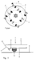
- FIG. 5 is a sectional view of a part of a rotational member according to the embodiment shown in FIG. 2 b.
- FIG. 1 shows a rotary disc according to prior art technology seen along its rotational axis 3 .
- the rotary disc 1 are arranged four cleaning nozzles 2 that are oriented such that supplied water is discharged in a direction with a velocity component that is mainly parallel with the rotational axis 3 , i.e. perpendicularly (up) from the paper plane, and a velocity component that is mainly parallel with the tangent of an imaginary circle at the location of each cleaning nozzle 2 .
- This tangential velocity component is for all cleaning nozzles concerned oriented clockwise (towards right).
- the cleaning nozzles and thereby the rotary disc to which they are attached are met with a counter force that turns the disc towards left as shown by the arrow R.
- the tangential velocity component of the water jet provides rotation to the rotary disc while the velocity component parallel to the rotational axis provides a cleaning pressure on the surface to be cleaned and which will normally be mainly parallel with the rotary disc.
- the water jet from each of the cleaning nozzles will typically has a certain spread, either conically or preferably fan-shaped, as indicated by the three arrows forming an acute angle “fan”.
- FIG. 2 a shows a rotary disc according to the present invention. It has the same basic components as the disc of FIG. 1 , but comprises in addition a gear 5 that may be engaged by an external motor, not shown, that is able to turn the disc independent of the water being discharged from the cleaning nozzles 2 . Contrary to the cleaning nozzles of FIG. 1 the cleaning nozzles are such oriented that the tangential velocity component from each of the cleaning nozzles is directed counter clockwise. According to the invention the orientation (inclination) of the cleaning nozzles is not an obstacle for a counter clockwise rotation of the rotary disc, i.e. against the force on the rotary disc made up of the sum of the tangential velocity components of the jets from the cleaning nozzles.
- FIG. 1 shows a rotary disc according to the present invention. It has the same basic components as the disc of FIG. 1 , but comprises in addition a gear 5 that may be engaged by an external motor, not shown, that is able to turn the disc independent of the water being discharged
- the rotary disc according to FIG. 2 has a total of four cleaning nozzles that is mutually spaced 90 degrees apart close to the periphery of the rotary disc.
- the water is supplied to the disc through a hollow spindle arranged concentrically with the rotational axis 3 .
- the water jet from each cleaning nozzle will have a certain spread, for example fan-shaped or in the form of more or less acute cone. In the Figures this is indicated with small arrows with an acute fan-shape.
- the direction of the water jets can therefore hardly be defined very precisely.
- the direction of such a fan-shaped spray of water herein is compared with e.g. the tangent of the imaginary circle where the nozzle in question is localized, it is understood that it is the central portion of that spray that is basis for the comparison with the tangent, while the more peripheral portions of the same spray necessarily will have somewhat deviant directions.
- the velocity component V p that is parallel with the rotary disc also is mainly parallel with the tangent to the imaginary circle concentrically with the rotary disc at which each respective nozzle is attached.
- FIG. 2 b shows a particularly preferred embodiment of the invention, departing from the variant shown in FIG. 2 a in that the direction of the water jet from each of the nozzles is such that the velocity component V p that is not perpendicular to the surface to be cleaned, is not parallel with the tangent of the imaginary circle at which the nozzles are attached, but is pointed outwards in relation to the tangent.
- the velocity component V p may as shown be decomposed into two velocity components, V r and V t , where V r is radial in relation to the rotary disc or the imaginary circle concentrically with the rotary disc at which each respective nozzle is attached, while V t is tangential in relation to the same circle.
- FIG. 3 shows a variant of the rotary disc shown in FIG. 2 b , where the sole difference is that it comprises only three cleaning nozzles and that these therefore are spaced apart with a mutual angular distance of 120 degrees.
- FIG. 4 shows a different embodiment, with a rotary disc 11 that has cleaning nozzles 2 , 2 ′ distributed along two concentric circular lines, with four nozzles on each circular line.
- the cleaning nozzles 2 ′ on the inner circular line are displaced by an angle of 45 degrees compared to the nozzles 2 on the outer circular line.
- the tangential velocity component V t for the liquid jets from all cleaning nozzles on both circular lines are counter clockwise.
- the rotary disc is, as shown by the arrow R, arranged to rotate counter clockwise in the same manner as shown in FIGS. 2 a , 2 b , and 3 .
- the nozzles along the outer circle are in the same manner as in FIGS.
- FIG. 5 shows a sectional view of a particularly preferred embodiment of the peripheral part of the rotary disc.
- the rotary disc 1 is mainly flat on both the side 6 facing the surface 8 to be cleaned and on the side 7 facing away from surface 8 .
- the rotary disc In a narrow area 9 of its periphery the rotary disc has, on the side facing the cleaning surface, a ring shaped area tapered away from the surface 8 , and the outer edge 10 of the tapered area is rounded over to the opposite side 7 .
- This design has proven very beneficial in that the rotary disc thereby is provided with a lifting force away from the surface 8 to be cleaned along the periphery, said lift compensating somewhat the strong sectional force that occurs close to the centre of the disc.
- a certain suction force between the rotary disc and the surface is desired, but it is not desired that this suction becomes so strong that the device holding the rotary disc can not be easily moved along the surface to be cleaned, that typically may be a ship hull. While the rotary disc is shown flat on both sides in FIG. 5 , shapes deviating from this may also be used, e.g. with a concave side facing the surface to be cleaned. In any case the shape of the cleaning disc will be mainly even around its entire circumference, so that arbitrary radial sections through the disc will have substantially the same shape and size.
- the cleaning effect of the device according to the invention is very good even at comparatively low water pressures, such as a water pressure in the range 150 to 1250 bars. It is thus a significant advantage in connection with cleaning of large and heavy contaminated surfaces requiring a significant cleaning effect, to use rotary discs with a rotation that is determined by an external motor compared to a rotation that is induced by the force from the cleaning nozzles.
- a more preferred water pressure is within the range 250-350 bars.
- the primary aspect of the present invention is that an excellent cleaning effect is achieved while maintaining a high degree of freedom with respect to combination of water pressure, inclination of nozzles and rotational speed of the discs for any given cleaning operation.
- the rotational speed is determined independent of the liquid pressure and independent of the nozzles' inclination. Whether the inclination of the nozzles is altered by means of interchangeable individual nozzles or by replacement of the discs with discs having a fixed, but different orientation of its nozzles, is in this connection of less importance. Both these solutions are within the frame of the invention.
- the device according to the present invention is developed for and has its primary utilization for cleaning of ship hulls and primarily the parts of the ship hulls that normally are submerged in water.
- a device according to the invention will typically comprise three or four rotary discs and be attached to an ROV conveniently adapted for the purpose.
- an ROV will be bistable and have thrusters that ensure that it in any orientation is able to rest against—or go along—a ship hull while the cleaning is conducted.
- ROVs having properties suitable for this purpose so this feature is not part of the present invention.
- the device according to the present invention is also well suited for cleaning large surfaces on land and will for such purpose be carried by smaller units that are transported either manually or by means of a separate motor. Under any circumstances it is preferred that the device comprises per se known means for positioning, i.e. to ensure that the rotary discs at all times are held substantially parallel with and at a predetermined distance from the surface to be cleaned.
- the distance between cleaning nozzle and the surface will be comparatively short, e.g. in the range between 0.3 and 4 cm and more typically between 0.5 and 2 cm.
- the equipment for positioning of the rotary discs will typically comprise a frame on which one or more discs are attached and wheels are mounted to the frame or possibly to individual discs, said wheels being adapted during the cleaning operation to rest against the surface to be cleaned. Wheels 12 mounted on a rotary disc 1 are shown in FIGS. 3 and 5 . Such positioning equipment is prior art technology and therefore not described in more detail here.
- Cleaning rig with 3 rotary discs (kl. 11:00) of a total width 1.2 m. Cleaning of 4 steel plates back and forth - duration ca. 20 seconds Pressure 220 bar. Rotation 500 rpm Sample 3 Sample of water in test vessel subsequent to second cleaning.
- TBT Tributyltin
- DBT Dibutyltin
- MBT Monobutyltin
- TFT Triphenyltin
- TBT may be decomposed into DBT. MBT and TFT and it is therefore required to analyze all these compounds to obtain a correct picture of total leakage of organic tin compounds during cleaning
Landscapes
- Chemical & Material Sciences (AREA)
- Engineering & Computer Science (AREA)
- Combustion & Propulsion (AREA)
- Mechanical Engineering (AREA)
- Ocean & Marine Engineering (AREA)
- Cleaning By Liquid Or Steam (AREA)
- Nozzles (AREA)
- Detergent Compositions (AREA)
- Catching Or Destruction (AREA)
- Treatments Of Macromolecular Shaped Articles (AREA)
Applications Claiming Priority (3)
| Application Number | Priority Date | Filing Date | Title |
|---|---|---|---|
| NO20034978 | 2003-11-10 | ||
| NO20034978A NO319207B1 (no) | 2003-11-10 | 2003-11-10 | Anordning for rengjoring av overflater sa som skipsskrog |
| PCT/NO2004/000339 WO2005044657A1 (en) | 2003-11-10 | 2004-11-10 | Device for cleaning subsea surfaces such as ship hulls |
Publications (2)
| Publication Number | Publication Date |
|---|---|
| US20070051392A1 US20070051392A1 (en) | 2007-03-08 |
| US7699066B2 true US7699066B2 (en) | 2010-04-20 |
Family
ID=29775162
Family Applications (1)
| Application Number | Title | Priority Date | Filing Date |
|---|---|---|---|
| US10/578,622 Expired - Fee Related US7699066B2 (en) | 2003-11-10 | 2004-11-10 | Device for cleaning subsea surfaces such as ship hulls |
Country Status (9)
| Country | Link |
|---|---|
| US (1) | US7699066B2 (de) |
| EP (1) | EP1685022B1 (de) |
| JP (1) | JP2007510588A (de) |
| KR (1) | KR101157610B1 (de) |
| AT (1) | ATE496824T1 (de) |
| CA (1) | CA2545389C (de) |
| DE (1) | DE602004031251D1 (de) |
| NO (1) | NO319207B1 (de) |
| WO (1) | WO2005044657A1 (de) |
Cited By (3)
| Publication number | Priority date | Publication date | Assignee | Title |
|---|---|---|---|---|
| US20100301139A1 (en) * | 2009-05-29 | 2010-12-02 | Seaward Marine Services Inc. | Rotating spray head and system for induced suction generation |
| US9168786B2 (en) | 2011-12-02 | 2015-10-27 | Helical Robotics, Llc | Mobile robot |
| US10342326B2 (en) | 2016-06-06 | 2019-07-09 | Saudi Arabian Oil Company | Underwater marine growth brushing mechanism with passive self-adjust for curved surfaces |
Families Citing this family (11)
| Publication number | Priority date | Publication date | Assignee | Title |
|---|---|---|---|---|
| NO20083079L (no) | 2008-07-11 | 2010-01-12 | Mpi Trond Sivertsen | Renseapparat for fjerning av marin begroning og anvendelse av apparat. |
| NZ601415A (en) * | 2010-02-03 | 2014-07-25 | Tor Mikal Ostervold | Tool and method for cleaning surfaces subsea |
| NO332875B1 (no) * | 2010-11-29 | 2013-01-28 | Environtec As | Innretning og farkost for rensing av overflater |
| EP2743173A1 (de) * | 2012-12-11 | 2014-06-18 | C-leanship Aps | Untertauchfähiges Reinigungssystem |
| CN103316860A (zh) * | 2013-06-29 | 2013-09-25 | 国家电网公司 | 一种变压器风机叶轮清洗专用装置 |
| NO343072B1 (en) * | 2017-04-28 | 2018-10-29 | Mpi As | An underwater cleaning device and apparatus |
| KR102049385B1 (ko) * | 2018-06-11 | 2019-11-27 | 재단법인 자동차융합기술원 | 회전식 세차장치 |
| CN110238186A (zh) * | 2019-06-10 | 2019-09-17 | 诸暨市众创机械设备厂 | 一种基于曲柄滑块原理的化学法土壤治理用设备 |
| WO2023052496A1 (en) * | 2021-09-30 | 2023-04-06 | Hydro Hull Cleaning A/S | A hull cleaning device and a method of cleaning a hull |
| NO347393B1 (en) | 2022-04-05 | 2023-10-16 | Environtec Aqua As | A surface-cleaning device and vehicle |
| CN117341926B (zh) * | 2023-11-08 | 2026-03-24 | 太平洋海洋工程(舟山)有限公司 | 船体外侧面清洗装置及清洗方法 |
Citations (14)
| Publication number | Priority date | Publication date | Assignee | Title |
|---|---|---|---|---|
| US3420444A (en) * | 1965-06-14 | 1969-01-07 | Salen & Wicander Ab | Apparatus for washing the cargo tanks of ships,particularly oil tankers |
| US3829019A (en) | 1972-02-02 | 1974-08-13 | Chaska Chem Co Inc | Spinner assembly |
| US3946692A (en) * | 1973-12-28 | 1976-03-30 | Phoceenne Sous Marine - Psm Les Hommes Grenouilies Du Port De Marseille | Device for cleaning ship's hulls and other immersed surfaces |
| US4314521A (en) * | 1976-11-04 | 1982-02-09 | Trelleborg Marin Aktiebolag | Method and apparatus in the treatment of underwater surfaces of fixed or floating constructions |
| US4574722A (en) * | 1982-10-06 | 1986-03-11 | Mitsui Engineering & Shipbuilding Co., Ltd. | Underwater cleaning apparatus |
| US4604960A (en) * | 1984-04-04 | 1986-08-12 | Macsea Marine Services Company, Inc. | Apparatus for cleaning underwater surfaces |
| US4838193A (en) * | 1986-12-23 | 1989-06-13 | Tak Josephus A M V D | Scrubbing machine |
| US4926775A (en) | 1986-08-21 | 1990-05-22 | Andorsen John P | Device for cleaning surfaces, particularly in water |
| US5048445A (en) | 1989-09-08 | 1991-09-17 | Cavi-Tech, Inc. | Fluid jet system and method for underwater maintenance of ship performance |
| RU2122961C1 (ru) | 1998-05-18 | 1998-12-10 | Шильниов Сергей Николаевич | Инструмент для подводной гидродинамической очистки поверхности |
| US5884642A (en) | 1997-08-07 | 1999-03-23 | Broadbent Spray Rentals | Remotely controlled pressurized liquid dispensing mobile unit |
| NO310902B1 (no) | 1999-11-11 | 2001-09-17 | John Peter Andorsen | Anordning ved renseapparat for marine strukturer |
| EP1216761A1 (de) | 1999-08-09 | 2002-06-26 | Vyacheslav Ivanovich Larin | Vorrichtung zum hydrodynamischen reinigen von oberflächen und varianten |
| US6425340B1 (en) | 1995-03-22 | 2002-07-30 | Mcguire Dennis | Apparatus and method for removing coatings from the hulls of vessels using ultra-high pressure water |
Family Cites Families (2)
| Publication number | Priority date | Publication date | Assignee | Title |
|---|---|---|---|---|
| JPH08323305A (ja) * | 1995-05-31 | 1996-12-10 | Mitsubishi Electric Corp | 洗浄装置 |
| JP2000295939A (ja) * | 1999-04-12 | 2000-10-24 | Kanmon Dock Service Kk | 海洋構造物の洗浄装置 |
-
2003
- 2003-11-10 NO NO20034978A patent/NO319207B1/no not_active IP Right Cessation
-
2004
- 2004-11-10 EP EP04800187A patent/EP1685022B1/de not_active Expired - Lifetime
- 2004-11-10 KR KR1020067008989A patent/KR101157610B1/ko not_active Expired - Fee Related
- 2004-11-10 JP JP2006539416A patent/JP2007510588A/ja active Pending
- 2004-11-10 AT AT04800187T patent/ATE496824T1/de not_active IP Right Cessation
- 2004-11-10 CA CA2545389A patent/CA2545389C/en not_active Expired - Fee Related
- 2004-11-10 US US10/578,622 patent/US7699066B2/en not_active Expired - Fee Related
- 2004-11-10 DE DE602004031251T patent/DE602004031251D1/de not_active Expired - Lifetime
- 2004-11-10 WO PCT/NO2004/000339 patent/WO2005044657A1/en not_active Ceased
Patent Citations (14)
| Publication number | Priority date | Publication date | Assignee | Title |
|---|---|---|---|---|
| US3420444A (en) * | 1965-06-14 | 1969-01-07 | Salen & Wicander Ab | Apparatus for washing the cargo tanks of ships,particularly oil tankers |
| US3829019A (en) | 1972-02-02 | 1974-08-13 | Chaska Chem Co Inc | Spinner assembly |
| US3946692A (en) * | 1973-12-28 | 1976-03-30 | Phoceenne Sous Marine - Psm Les Hommes Grenouilies Du Port De Marseille | Device for cleaning ship's hulls and other immersed surfaces |
| US4314521A (en) * | 1976-11-04 | 1982-02-09 | Trelleborg Marin Aktiebolag | Method and apparatus in the treatment of underwater surfaces of fixed or floating constructions |
| US4574722A (en) * | 1982-10-06 | 1986-03-11 | Mitsui Engineering & Shipbuilding Co., Ltd. | Underwater cleaning apparatus |
| US4604960A (en) * | 1984-04-04 | 1986-08-12 | Macsea Marine Services Company, Inc. | Apparatus for cleaning underwater surfaces |
| US4926775A (en) | 1986-08-21 | 1990-05-22 | Andorsen John P | Device for cleaning surfaces, particularly in water |
| US4838193A (en) * | 1986-12-23 | 1989-06-13 | Tak Josephus A M V D | Scrubbing machine |
| US5048445A (en) | 1989-09-08 | 1991-09-17 | Cavi-Tech, Inc. | Fluid jet system and method for underwater maintenance of ship performance |
| US6425340B1 (en) | 1995-03-22 | 2002-07-30 | Mcguire Dennis | Apparatus and method for removing coatings from the hulls of vessels using ultra-high pressure water |
| US5884642A (en) | 1997-08-07 | 1999-03-23 | Broadbent Spray Rentals | Remotely controlled pressurized liquid dispensing mobile unit |
| RU2122961C1 (ru) | 1998-05-18 | 1998-12-10 | Шильниов Сергей Николаевич | Инструмент для подводной гидродинамической очистки поверхности |
| EP1216761A1 (de) | 1999-08-09 | 2002-06-26 | Vyacheslav Ivanovich Larin | Vorrichtung zum hydrodynamischen reinigen von oberflächen und varianten |
| NO310902B1 (no) | 1999-11-11 | 2001-09-17 | John Peter Andorsen | Anordning ved renseapparat for marine strukturer |
Cited By (6)
| Publication number | Priority date | Publication date | Assignee | Title |
|---|---|---|---|---|
| US20100301139A1 (en) * | 2009-05-29 | 2010-12-02 | Seaward Marine Services Inc. | Rotating spray head and system for induced suction generation |
| US8327787B2 (en) * | 2009-05-29 | 2012-12-11 | Seward Marine Services Inc. | Rotating spray head and system for induced suction generation |
| US9168786B2 (en) | 2011-12-02 | 2015-10-27 | Helical Robotics, Llc | Mobile robot |
| US9545965B2 (en) | 2011-12-02 | 2017-01-17 | Helical Robotics, Llc | Mobile robot |
| US10342326B2 (en) | 2016-06-06 | 2019-07-09 | Saudi Arabian Oil Company | Underwater marine growth brushing mechanism with passive self-adjust for curved surfaces |
| US11224285B2 (en) | 2016-06-06 | 2022-01-18 | Saudi Arabian Oil Company | Underwater marine growth brushing mechanism with passive self-adjust for curved surfaces |
Also Published As
| Publication number | Publication date |
|---|---|
| KR101157610B1 (ko) | 2012-06-18 |
| NO319207B1 (no) | 2005-06-27 |
| EP1685022B1 (de) | 2011-01-26 |
| ATE496824T1 (de) | 2011-02-15 |
| EP1685022A1 (de) | 2006-08-02 |
| CA2545389A1 (en) | 2005-05-19 |
| CA2545389C (en) | 2012-05-29 |
| JP2007510588A (ja) | 2007-04-26 |
| WO2005044657A1 (en) | 2005-05-19 |
| DE602004031251D1 (de) | 2011-03-10 |
| US20070051392A1 (en) | 2007-03-08 |
| KR20060129184A (ko) | 2006-12-15 |
| NO20034978D0 (no) | 2003-11-10 |
Similar Documents
| Publication | Publication Date | Title |
|---|---|---|
| US7699066B2 (en) | Device for cleaning subsea surfaces such as ship hulls | |
| US5174222A (en) | Apparatus for cleaning of ship hulls | |
| US5628271A (en) | Apparatus and method for removing coatings from the hulls of vessels using ultra-high pressure water | |
| CN104507591B (zh) | 用于清洁表面的清洁头、包括该清洁头的设备及清洁方法 | |
| EP3415412B1 (de) | Oberflächenreinigungsvorrichtung | |
| CN107107659B (zh) | 磁轮 | |
| US6595152B2 (en) | Apparatus and method for removing coatings from the hulls of vessels using ultra-high pressure water | |
| AU706798B2 (en) | Floating dock | |
| KR102205573B1 (ko) | 플로팅 도크에 설치되는 선체의 해양생물 제거용 자동세척장치 및 방법 | |
| KR20160068883A (ko) | 자동화된 보트 세척 도크 및 자동화된 보트 세척 도크에서 보트를 세척하는 방법 | |
| WO2020088740A1 (en) | A method and device for grooming ship hull from fouling during ships movement | |
| KR20070000427A (ko) | 표면 상의 해양 생물 부착물을 처리하는 방법 및 장치 | |
| US4011827A (en) | Machine for cleaning the bottom of boats | |
| US6067921A (en) | Device for external cleaning of ship's hulls | |
| US6209473B1 (en) | Treatment of an underwater surface | |
| Akinfiev et al. | A brief survey of ship hull cleaning devices. | |
| KR20210068496A (ko) | 선박 세척 장치 | |
| BR202019012783U2 (pt) | sistema de remoção, remanejamento e inspeção de vida marinha presente em estruturas flutuantes como navios e plataformas petrolíferas | |
| CN116215788A (zh) | 水下清洁装置和水下清洁系统 | |
| NO20180168A1 (en) | Cleaning apparatus for cleaning a submerged portion of a structure and method for use of said cleaning apparatus | |
| KR102691737B1 (ko) | 접안형 청소 플랜트 및 이를 이용한 청소 방법 | |
| NO346336B1 (en) | Cleaning disc for cleaning a submerged portion of a structure | |
| KR101516202B1 (ko) | 선체 벽면 작업용 로봇 | |
| KR20170019682A (ko) | 프로펠러 이물질 고착 방지장치 및 이를 가지는 선박 | |
| Stateczny et al. | Modern Methods of Hull Cleaning Using Remote Operated Vehicle |
Legal Events
| Date | Code | Title | Description |
|---|---|---|---|
| AS | Assignment |
Owner name: CLEANHULL NORWAY AS,NORWAY Free format text: ASSIGNMENT OF ASSIGNORS INTEREST;ASSIGNORS:ANDERSEN, ROBERT;SPERRE, THOR OLAV E.;REEL/FRAME:017896/0627 Effective date: 20060410 Owner name: CLEANHULL NORWAY AS, NORWAY Free format text: ASSIGNMENT OF ASSIGNORS INTEREST;ASSIGNORS:ANDERSEN, ROBERT;SPERRE, THOR OLAV E.;REEL/FRAME:017896/0627 Effective date: 20060410 |
|
| STCF | Information on status: patent grant |
Free format text: PATENTED CASE |
|
| FPAY | Fee payment |
Year of fee payment: 4 |
|
| FEPP | Fee payment procedure |
Free format text: PAYOR NUMBER ASSIGNED (ORIGINAL EVENT CODE: ASPN); ENTITY STATUS OF PATENT OWNER: SMALL ENTITY |
|
| MAFP | Maintenance fee payment |
Free format text: PAYMENT OF MAINTENANCE FEE, 8TH YR, SMALL ENTITY (ORIGINAL EVENT CODE: M2552) Year of fee payment: 8 |
|
| FEPP | Fee payment procedure |
Free format text: MAINTENANCE FEE REMINDER MAILED (ORIGINAL EVENT CODE: REM.); ENTITY STATUS OF PATENT OWNER: SMALL ENTITY |
|
| LAPS | Lapse for failure to pay maintenance fees |
Free format text: PATENT EXPIRED FOR FAILURE TO PAY MAINTENANCE FEES (ORIGINAL EVENT CODE: EXP.); ENTITY STATUS OF PATENT OWNER: SMALL ENTITY |
|
| STCH | Information on status: patent discontinuation |
Free format text: PATENT EXPIRED DUE TO NONPAYMENT OF MAINTENANCE FEES UNDER 37 CFR 1.362 |
|
| FP | Lapsed due to failure to pay maintenance fee |
Effective date: 20220420 |