US7717025B2 - Fluid actuator with limit sensors and fluid limit valves - Google Patents
Fluid actuator with limit sensors and fluid limit valves Download PDFInfo
- Publication number
- US7717025B2 US7717025B2 US11/691,482 US69148207A US7717025B2 US 7717025 B2 US7717025 B2 US 7717025B2 US 69148207 A US69148207 A US 69148207A US 7717025 B2 US7717025 B2 US 7717025B2
- Authority
- US
- United States
- Prior art keywords
- fluid
- limit
- cylinder
- main piston
- additional
- Prior art date
- Legal status (The legal status is an assumption and is not a legal conclusion. Google has not performed a legal analysis and makes no representation as to the accuracy of the status listed.)
- Active, expires
Links
- 239000012530 fluid Substances 0.000 title claims abstract description 1118
- 238000000926 separation method Methods 0.000 claims abstract description 21
- 238000012423 maintenance Methods 0.000 claims description 26
- 238000013459 approach Methods 0.000 claims description 25
- 238000000034 method Methods 0.000 claims description 23
- 230000003213 activating effect Effects 0.000 claims description 22
- 230000004913 activation Effects 0.000 claims description 7
- 230000002596 correlated effect Effects 0.000 claims 4
- 230000006835 compression Effects 0.000 claims 2
- 238000007906 compression Methods 0.000 claims 2
- 230000000875 corresponding effect Effects 0.000 claims 1
- 238000010276 construction Methods 0.000 abstract description 4
- 238000007667 floating Methods 0.000 description 64
- ZZUFCTLCJUWOSV-UHFFFAOYSA-N furosemide Chemical compound C1=C(Cl)C(S(=O)(=O)N)=CC(C(O)=O)=C1NCC1=CC=CO1 ZZUFCTLCJUWOSV-UHFFFAOYSA-N 0.000 description 53
- 238000013016 damping Methods 0.000 description 24
- 238000012937 correction Methods 0.000 description 19
- 238000006073 displacement reaction Methods 0.000 description 10
- 230000008901 benefit Effects 0.000 description 8
- 238000001514 detection method Methods 0.000 description 7
- 238000012544 monitoring process Methods 0.000 description 7
- 239000006096 absorbing agent Substances 0.000 description 5
- 230000035939 shock Effects 0.000 description 5
- 230000000694 effects Effects 0.000 description 4
- 230000001105 regulatory effect Effects 0.000 description 4
- 230000001276 controlling effect Effects 0.000 description 3
- 238000013461 design Methods 0.000 description 3
- 239000012190 activator Substances 0.000 description 2
- 230000007423 decrease Effects 0.000 description 2
- 238000010586 diagram Methods 0.000 description 2
- 238000005259 measurement Methods 0.000 description 2
- 230000008569 process Effects 0.000 description 2
- 241000482967 Diloba caeruleocephala Species 0.000 description 1
- 230000009471 action Effects 0.000 description 1
- 238000005452 bending Methods 0.000 description 1
- 230000002457 bidirectional effect Effects 0.000 description 1
- 230000008878 coupling Effects 0.000 description 1
- 238000010168 coupling process Methods 0.000 description 1
- 238000005859 coupling reaction Methods 0.000 description 1
- 230000002349 favourable effect Effects 0.000 description 1
- 238000005187 foaming Methods 0.000 description 1
- 230000008014 freezing Effects 0.000 description 1
- 238000007710 freezing Methods 0.000 description 1
- 238000012986 modification Methods 0.000 description 1
- 230000004048 modification Effects 0.000 description 1
- 230000009467 reduction Effects 0.000 description 1
- 230000008672 reprogramming Effects 0.000 description 1
- 230000004044 response Effects 0.000 description 1
- 238000005201 scrubbing Methods 0.000 description 1
- 239000007787 solid Substances 0.000 description 1
- 238000009987 spinning Methods 0.000 description 1
Images




Classifications
-
- B—PERFORMING OPERATIONS; TRANSPORTING
- B62—LAND VEHICLES FOR TRAVELLING OTHERWISE THAN ON RAILS
- B62D—MOTOR VEHICLES; TRAILERS
- B62D5/00—Power-assisted or power-driven steering
- B62D5/06—Power-assisted or power-driven steering fluid, i.e. using a pressurised fluid for most or all the force required for steering a vehicle
- B62D5/09—Power-assisted or power-driven steering fluid, i.e. using a pressurised fluid for most or all the force required for steering a vehicle characterised by means for actuating valves
-
- F—MECHANICAL ENGINEERING; LIGHTING; HEATING; WEAPONS; BLASTING
- F15—FLUID-PRESSURE ACTUATORS; HYDRAULICS OR PNEUMATICS IN GENERAL
- F15B—SYSTEMS ACTING BY MEANS OF FLUIDS IN GENERAL; FLUID-PRESSURE ACTUATORS, e.g. SERVOMOTORS; DETAILS OF FLUID-PRESSURE SYSTEMS, NOT OTHERWISE PROVIDED FOR
- F15B13/00—Details of servomotor systems ; Valves for servomotor systems
- F15B13/02—Fluid distribution or supply devices characterised by their adaptation to the control of servomotors
-
- F—MECHANICAL ENGINEERING; LIGHTING; HEATING; WEAPONS; BLASTING
- F15—FLUID-PRESSURE ACTUATORS; HYDRAULICS OR PNEUMATICS IN GENERAL
- F15B—SYSTEMS ACTING BY MEANS OF FLUIDS IN GENERAL; FLUID-PRESSURE ACTUATORS, e.g. SERVOMOTORS; DETAILS OF FLUID-PRESSURE SYSTEMS, NOT OTHERWISE PROVIDED FOR
- F15B15/00—Fluid-actuated devices for displacing a member from one position to another; Gearing associated therewith
- F15B15/08—Characterised by the construction of the motor unit
- F15B15/14—Characterised by the construction of the motor unit of the straight-cylinder type
- F15B15/1409—Characterised by the construction of the motor unit of the straight-cylinder type with two or more independently movable working pistons
-
- F—MECHANICAL ENGINEERING; LIGHTING; HEATING; WEAPONS; BLASTING
- F15—FLUID-PRESSURE ACTUATORS; HYDRAULICS OR PNEUMATICS IN GENERAL
- F15B—SYSTEMS ACTING BY MEANS OF FLUIDS IN GENERAL; FLUID-PRESSURE ACTUATORS, e.g. SERVOMOTORS; DETAILS OF FLUID-PRESSURE SYSTEMS, NOT OTHERWISE PROVIDED FOR
- F15B15/00—Fluid-actuated devices for displacing a member from one position to another; Gearing associated therewith
- F15B15/08—Characterised by the construction of the motor unit
- F15B15/14—Characterised by the construction of the motor unit of the straight-cylinder type
- F15B15/149—Fluid interconnections, e.g. fluid connectors, passages
-
- F—MECHANICAL ENGINEERING; LIGHTING; HEATING; WEAPONS; BLASTING
- F15—FLUID-PRESSURE ACTUATORS; HYDRAULICS OR PNEUMATICS IN GENERAL
- F15B—SYSTEMS ACTING BY MEANS OF FLUIDS IN GENERAL; FLUID-PRESSURE ACTUATORS, e.g. SERVOMOTORS; DETAILS OF FLUID-PRESSURE SYSTEMS, NOT OTHERWISE PROVIDED FOR
- F15B15/00—Fluid-actuated devices for displacing a member from one position to another; Gearing associated therewith
- F15B15/20—Other details, e.g. assembly with regulating devices
- F15B15/204—Control means for piston speed or actuating force without external control, e.g. control valve inside the piston
-
- F—MECHANICAL ENGINEERING; LIGHTING; HEATING; WEAPONS; BLASTING
- F15—FLUID-PRESSURE ACTUATORS; HYDRAULICS OR PNEUMATICS IN GENERAL
- F15B—SYSTEMS ACTING BY MEANS OF FLUIDS IN GENERAL; FLUID-PRESSURE ACTUATORS, e.g. SERVOMOTORS; DETAILS OF FLUID-PRESSURE SYSTEMS, NOT OTHERWISE PROVIDED FOR
- F15B15/00—Fluid-actuated devices for displacing a member from one position to another; Gearing associated therewith
- F15B15/20—Other details, e.g. assembly with regulating devices
- F15B15/22—Other details, e.g. assembly with regulating devices for accelerating or decelerating the stroke
- F15B15/225—Other details, e.g. assembly with regulating devices for accelerating or decelerating the stroke with valve stems operated by contact with the piston end face or with the cylinder wall
-
- F—MECHANICAL ENGINEERING; LIGHTING; HEATING; WEAPONS; BLASTING
- F15—FLUID-PRESSURE ACTUATORS; HYDRAULICS OR PNEUMATICS IN GENERAL
- F15B—SYSTEMS ACTING BY MEANS OF FLUIDS IN GENERAL; FLUID-PRESSURE ACTUATORS, e.g. SERVOMOTORS; DETAILS OF FLUID-PRESSURE SYSTEMS, NOT OTHERWISE PROVIDED FOR
- F15B15/00—Fluid-actuated devices for displacing a member from one position to another; Gearing associated therewith
- F15B15/20—Other details, e.g. assembly with regulating devices
- F15B15/24—Other details, e.g. assembly with regulating devices for restricting the stroke
Definitions
- This invention relates the construction of a valve for hydraulic fluid leak detection and correction in hydraulic fluid linkages, insuring that the hydraulic fluid linkages are accurate at all times.
- the reliable accurate hydraulic fluid linkages with adjustable limit stops can be used to replace complex mechanical linkages.
- Hydraulic circuits have not been able to fully replace mechanical linkages in precision applications, such as vehicle steering and other systems requiring accurate reliable correlation which linkages provided.
- Mechanical linkages reliably correlate the movement of mechanical components.
- Hydraulic circuits used to replace mechanical linkages use two or more linear actuators, rotary actuators or fluid motors to control the movement of mechanical components. In a hydraulic circuit these hydraulic actuators or motors are connected by a hydraulic fluid conduit with possible intermediary fluid control valves and fluid pumps.
- the hydraulic circuits used to replace mechanical linkages are hydraulic linkages. Replacing mechanical linkages with hydraulic linkages have significant advantages over mechanical linkages. Hydraulic conduits required to construct hydraulic linkages can be easily routed. Hydraulic circuits can easily switch operating modes.
- the hydraulic circuit can form a hydraulic linkage between a different set of mechanical components or the mechanical components can be controlled independently in a completely uncorrelated manner.
- hydraulic circuits need to be able to detect and correct fluid loss in hydraulic linkages and require limit stops to prevent damage caused by extending or retracing too far and/or too hard.
- the hydraulic linkage can include leakage compensation and leakage location detection and allow for accurate control over the extension and retraction of a piston in the fluid actuator.
- Mechanical stops prevent over extension and over retraction and are strong enough to resist the full force of the hydraulic actuator or the full force of the mechanical load.
- Conventional actuators include mechanical stops. However, the mechanical stops included in conventional actuators are not adjustable. Mechanical components in different orientations may require mechanical limit stops to be repositioned. Without adjustable mechanical actuator stops, actuator movement often cannot be stopped before damaging over extension or over retraction occurs.
- Piston bypass valves have been constructed to activate the piston when it is in proximity to the end cap. For example, see U.S. Pat. Nos. 5,425,305, 6,170,383 (Mauritz). The described art does not provide location adjustable piston bypass valves.
- Re-phasing hydraulic circuits have been constructed of re-phasing cylinders utilizing fluid bypass ports.
- U.S. Pat. No. 4,463,563 (Krehbiel).
- the described art does not provide location adjustable piston bypass valves. Also, neither the location nor the pressure at which these pistons are re-phased, by means of a bypass port, is adjustable.
- Hydraulic steering linkages have been constructed from a pair of hydraulically linked hydraulic cylinders. For example see U.S. Pat. Nos. 6,179,315 (Boriack) 3,212,793 (Pietrotroia). There is no means of detecting or correcting for hydraulic fluid leakage from the hydraulic linkage described in this prior art. Hydraulic leakage occurs in virtually all hydraulic circuits. Leakage can occur as hydraulic fluid lost from the hydraulic circuit, or as hydraulic fluid leaking across actuator seals.
- Cushioning devices are constructed for decelerating and stopping pistons by restricting fluid flow. For example, see U.S. Pat. Nos. 4,397,218 (Spring), 6,557,456 (Norton).
- the presented cushioning devices do not include a means of adjusting the extension and/or retraction limits at which the cushioning limit valves are activated or proportionally activating the cushioning limit valves.
- a limit switch with a sensing element is actuated when the operating actuator reaches an end position.
- the switching element stops the supply of hydraulic fluid to the operating actuator in response to the actuated sensing element.
- Proximity switches are used to detect the proximity of components before they come into contact. When proximity switches detect the limit position, valves are controlled to interrupt hydraulic supply to actuators preventing them from over extending or retracting.
- U.S. Pat. No. 4,165,674 (Weight). Rather than stopping or interrupting the hydraulic supply to actuators, the hydraulic flow can also be reduced, slowing the actuators' movement as it approaches the limit.
- a limit valve which controls the driving hydraulic flow by reducing the hydraulic pump stroke when the limit valve is moved to a predetermined limit is able to reduce the hydraulic flow as desired.
- U.S. Pat. No. 5,117,935 Hall.
- the limit sensors and valves designed to stop or reduce hydraulic supply to actuators cannot detect or correct hydraulic leakage in circuits. Separate mechanical stops are required to prevent mechanical loads from over extending or retracting the actuators.
- Leakage in hydraulic linkages can be compensated by continuously monitoring the position by a sensor on the control element and by a sensor on the driven element.
- the hydraulic flow to the actuators is continuously adjusted according to the monitored positions of the control and driven element.
- U.S. Pat. No. 7,028,469 Pierskrog
- the elements are linked by an electronic control system.
- This electronic monitoring system requires an electrical power supply at all times for the position sensors and the control valve solenoids.
- the electronic monitoring systems is only able to compensate for slow hydraulic leaks.
- the present invention is able to compensate for slow hydraulic leaks without requiring continuous monitoring of either the control or driven elements.
- the prior art method of compensating for hydraulic leaks by continuously monitoring the control and driven elements does not include adjustable mechanical stops required to prevent mechanical loads from over extending or retracting the actuators. Whereas the present invention does include adjustable mechanical stops.
- the present invention enables mechanical linkages to be replaced by hydraulic linkages in precision applications such as vehicle steering and other systems requiring accurate reliable correlation between mechanical components.
- the present invention integrates adjustable mechanical stops or cushions into hydraulic actuators. This allows hydraulic linkages to be used in operating situations where over limit movement must be prevented.
- the present invention enables detection and correction of hydraulic leakage at actuator's extension and retraction limits. Slow hydraulic leaks do not require continuous monitoring. Intermittent detection and correction of hydraulic leakage is sufficient.
- the present invention does not require a hydraulic source to be constantly available to correct for hydraulic leakage. More time is available to recharge the hydraulic pressure source between its usage for hydraulic leakage correction.
- the present invention provides hydraulic leakage detection and correction without the requirement of continuous monitoring and an electronic control system. As a result hydraulic linkages constructed are simpler and more reliable and can be safely used as a replacement for mechanical linkages.
- a fluid linkage circuit with limit sensors is integrated into a fluid actuator, such that when the fluid actuator extends to its extension limit or retracts to its retraction limit, the limit sensors will activate fluid valves to redirect fluid to bypass the fluid actuator's piston, thereby preventing over extension or over retraction and correcting for fluid leakage within a fluid linkage circuit.
- the location of the limit sensors are adjusted by adjusting the mechanical limit stops or cushions of the fluid actuator.
- FIG. 1 Isometric view of a Prior Art Fluid Actuator.
- FIG. 2 Cross Section view of the Prior Art Fluid Actuator shown in FIG. 1 taken along Cutting Plane A-A.
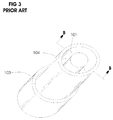
- FIG. 3 Isometric view of the Base Portion of the Prior Art Fluid Actuator shown in FIG. 1
- FIG. 4 Cross Section view of the Base Portion of the Prior Art Fluid Actuator shown in FIG. 2 taken along Cutting Plane B-B.
- FIG. 5 Isometric view of the Base Portion of the Fluid Actuator with an Integrated Fluid Limit Valve that has No Moving Parts.
- FIG. 6 Cross Section view of the Base Portion of the Fluid Actuator with an Integrated Fluid Limit Valve that has No Moving Parts shown in FIG. 5 taken along Cutting Plane C-C.
- FIG. 7 Isometric view of the Base Portion of the Fluid Actuator with a Fluid Limit Valve integrated into the Piston.
- FIG. 8 Cross Section view of the Base Portion of the Fluid Actuator with a Fluid Limit Valve integrated into the Piston shown in FIG. 7 taken along Cutting Plane D-D.
- FIG. 9 Isometric view of the Base Portion of the Fluid Actuator with a Fluid Limit Valve integrated in the End Cap.
- FIG. 10 Cross Section view of the Base Portion of the Fluid Actuator with a Fluid Limit Valve integrated in the End Cap shown in FIG. 9 taken along Cutting Plane E-E.
- FIG. 11 Isometric view of the Hydro Pneumatic Cylinder with Adjustable Mechanical Limits.
- FIG. 12 a Cross Section of Hydraulic Cylinder with Adjustable Mechanical Limits shown in FIG. 11 taken along Cutting Plane F-F
- FIG. 12 b Cross Section of Hydro Pneumatic Cylinder with Adjustable Mechanical Limits shown in FIG. 11 taken along Cutting Plane F-F
- FIG. 13 a Detailed Side Cross Section of Fluid Limit Valve shown in FIG. 12 a , FIG. 12 b which is taken along Cutting Plane F-F
- FIG. 13 b Detailed Side Cross Section of Fluid Limit Valve with External Fluid Leakage Correction Supply shown in FIG. 12 a , FIG. 12 b which is taken along Cutting Plane F-F
- FIG. 14 Basic fluid linkage utilizing the Fluid Limit Valve With Moving Parts
- FIG. 15 Basic fluid linkage utilizing the Fluid Limit Valve Without Moving Parts
- FIG. 16 Fluid Actuators with External Mechanical Limit Stops
- FIGS. 1 and 2 are identical to FIGS. 1 and 2
- FIG. 1 is an isometric view of a complete prior art fluid actuator.
- FIG. 2 is a sectional view taken along the cutting plane A-A of FIG. 1 .
- FIGS. 1 and 2 are identical to FIGS. 1 and 2
- Fluid flowing into cylinder base connection 205 forces piston 102 to move and piston rod 101 to extend.
- fluid is forced out of the cylinder head connection 208 .
- Fluid flowing into the cylinder head connection 208 forces piston 102 to move and piston rod 101 to retract.
- fluid is forced out of the cylinder base connection 205 .
- the prior art fluid actuator has a fluid connection 205 in the base and another fluid connection 208 in the head. The piston 102 does not pass over either the base 205 or the head 208 connection.
- the base connection 205 is always on the base side of the piston 102 .
- the head connection 208 is always on the head side of the piston 102 .
- FIG. 3 is an isometric view of the bottom portion of the complete prior art fluid actuator shown in FIG. 1 and FIG. 2 .
- FIG. 4 is a sectional view taken along the cutting plane B-B of FIG. 3 . Since the operation of a fluid actuator is symmetric, it is only necessary to examine either the top portion or bottom portion for purpose of understanding the fluid actuator's operation.
- Fluid flowing into cylinder base connection 205 forces piston 102 to move and piston rod 101 to extend.
- fluid is forced out of the cylinder head connection 208 .
- Fluid flowing into the cylinder head connection forces piston 102 to move and piston rod 101 to retract.
- fluid is forced out of the cylinder base connection 205 .
- the prior art fluid actuator has a fluid connection 205 in the base and another fluid inlet/outlet in the head. The piston 102 does not pass over either the base connection 205 or the head connection 208 .
- the base connection 205 is always on the base side of the piston 102 .
- the head connection 208 is always on the head side of the piston 102 .
- the fluid used in these circuits is incompressible with insignificant foaming characteristics, a vapour point well above expected operating temperatures, and a freezing point well below expected operating temperatures. Also, the viscosity cannot be prohibitively high; if gelling occurs, it is well below expected operating temperatures.
- FIG. 5 is an isometric view of the bottom portion of a fluid actuator with a fluid limit valve containing no moving parts.
- FIG. 6 is a sectional view taken along the cutting plane C-C of FIG. 5 .
- the piston 102 can be either on the head side or base side of the base fluid limit valve outlet holes 106 .
- the base fluid limit valve cover 117 covers the valve outlet holes 106 and provides a base fluid limit valve outlet 207 .
- a check valve will be attached to the fluid limit valve outlet 207 as later shown in fluid circuits. The check valve prevents fluid flowing into the fluid outlet 207 .
- FIG. 7 is an isometric view of the bottom portion of a fluid actuator with a closed fluid limit valve with moving parts.
- FIG. 8 is a sectional view taken along cutting plane D-D of FIG. 7 .
- the combined fluid actuator with fluid limit valve functions as a conventional prior art fluid actuator until the piston 101 extends sufficiently for the fluid limit poppet valve 674 to come into contact with the head poppet plunger.
- the poppet fluid limit valve return spring 673 is compressed and fluid limit poppet valve 674 opens.
- the fluid limit poppet valve 674 operates in this piston 102 extension fluid limit valve as described previously for the case of piston 102 retraction fluid limit valve. Later circuits describe how fluid limit valves used in this manner can detect and correct for fluid loss.
- FIG. 9 is an isometric view of the bottom portion of a fluid actuator with a closed fluid limit valve with moving parts.
- FIG. 10 is a sectional view taken along cutting plane E-E of FIG. 9 .
- the fluid limit valve outlet 207 is connected to the line to the cylinder head connection 208 .
- Fluid forced into the head connections 208 causes the piston 102 to retract. As the piston 102 retracts, fluid is forced out of the base connection 205 .
- the combined fluid actuator with fluid limit valve functions as a conventional prior art fluid actuator until the piston 102 retracts sufficiently to come into contact with the base poppet valve 674 .
- the force against the base poppet valve 674 compresses the poppet fluid limit valve return spring 144 and opens fluid limit poppet valve 674 .
- Piston 102 can retract until it comes in contact with base cap piston stop 105 . Fluid forced into the head connection 208 is also forced into the fluid limit valve outlet 207 .
- Fluid forced into the fluid limit valve outlet 207 can freely flow through the base poppet valve 674 and through the fluid limit valve out 671 and finally out of the base connection 205 .
- base cap piston stop 105 is required to restrain the piston 102 and protect against over retraction. Later circuits describe how fluid limit valves used in this manner can detect and correct for fluid loss.
- Fluid forced into the fluid limit valve head fluid connection can freely flow through the head poppet fluid limit valve and through the base connection and finally out of the head connection 208 .
- head cap piston stop is required to restrain the piston 102 and protect against over extension. Later circuits describe how fluid limit valves used in this manner can detect and correct for fluid loss.
- Hydro pneumatic and hydraulic cylinders with adjustable mechanical limits are used in steering, load leaving, roll control and many other fluid circuits requiring fluid actuators with adjustable mechanical limits or fluid leakage detection and correction within hydraulic linkages.
- the hydro pneumatic, hydraulic cylinders and the associated fluid limit valves with limit sensors are shown in FIG. 11 , 12 a, 12 b, 13 a, 13 b .
- FIG. 11 is an isometric view of the hydro pneumatic cylinders used in the load balance and roll control circuits.
- the hydro pneumatic cylinder shown in FIG. 11 does not include head or base mountings.
- a cross section of the hydraulic cylinder with adjustable mechanical limit sensors and fluid limit valves 550 , 551 is taken along the cutting plane F-F and shown in FIG. 12 a .
- FIG. 12 b A cross section of the hydro pneumatic cylinder is taken along the cutting plane F-F and shown in FIG. 12 b .
- FIGS. 12 a and 12 b the location of the hydraulic mechanical limit sensors and fluid limit valves 550 , 551 is shown.
- the detail cross section of the hydraulic fluid limit valve without external fluid leak correction supply is shown in FIG. 13 a .
- the detailed cross section of the hydraulic fluid limit valve with external fluid leak correction supply is shown in FIG. 13 b.
- the preferred embodiments, implementing the adjustable extension limit and associated head fluid limit valve 550 and the adjustable retraction limit and associated base fluid limit valve 551 are presented.
- the preferred methods of adjusting the extension or retraction limits is adjusting the measured value of extension and retraction limits when the piston position is measured electrically, or piston extension when the piston activates the mechanical limit sensor at extension and retraction limits. Both electrically activated limit sensors and mechanically activated limit sensors have advantages and disadvantages.
- the piston position is electrically measured.
- the limit sensors are activated when the piston reaches a predetermined measured position.
- the measured position corresponding to the extension limit of the head limit sensor can be reprogrammed.
- the extension limit of the head limit sensor and the retraction limit of the base limit sensor are adjusted by reprogramming the measured positions.
- Limit sensors activated a programmed measured piston locations do not need to be integrated into the cylinder construction.
- These electrically activated limit sensors can easily be housed in a separate control box attached to the cylinder or near the cylinder. This allows conventional cylinders with integrated electrical position measurement to be used without modifications.
- the electrical limit sensors require electrical power source for the cylinder position measurements and to drive solenoids opening and closing the fluid limit valves.
- the mechanical limit sensors are activated by the piston mechanically forcing the fluid limit valves to open.
- the mechanical limit sensors can be activated directly by the piston as show in FIG. 12 b or indirectly by means of fluid linkage.
- a fluid linkage can connect an external fluid limit valve to a hydraulic limit sensor integrated into the actuator.
- the limit sensor is activated when the main piston 102 is a distance away from the cylinder end by a floating piston. Rather than adjusting the position of the limit sensor, the distance at which the main piston 102 is away from the cylinder end is adjusted. As shown in FIG. 12 a , it is easy to adjust the distance the limit sensor and head fluid limit valve 550 is from the main piston 102 .
- the mechanical limit sensor is activated by the hydraulic floating head piston 686 mechanically forcing the head fluid limit valve 550 to open. It is easy to control the distance of the hydraulic floating head piston 686 from the main piston 102 by adjusting the amount of fluid between them. Similarly it is easy to adjust the distance of the limit sensor and the base fluid limit valve 551 from the main piston 102 , by adjusting the amount of hydraulic fluid between the floating base piston 688 and the main piston 102 .
- Mechanical limit sensors and fluid valves operate independently of an external power source.
- the hydraulically adjustable head chamber 655 between the main piston 102 and the floating head piston 686 mechanically limits the extension of the main piston 102 . The extension of the floating head piston 686 is limited by the cylinder head stops.
- the minimum separation between the main piston 102 and the floating head piston 686 is controlled by the amount of incompressible fluid in the head chamber 655 .
- the minimum separation of the main piston 102 from the cylinder head stops is adjusted by the amount of fluid in the head chamber 655 .
- the floating head piston 686 reaches the cylinder head stops, it also activates the mechanical limit sensor which opens the head fluid limit valve 550 .
- the open head fluid limit valve 550 allows additional fluid destined for the hydraulic base chamber 654 to bypass the fluid actuator. Additional fluid forced into the hydraulic base chamber 654 would force the floating base piston 688 to extend and consequently the main piston 102 would extend.
- the head fluid limit valve 550 prevents fluid forced into the base of the fluid actuator from forcing the main piston 102 to over extend.
- the hydraulically adjustable chamber 656 between the main piston 102 and the floating base piston 688 mechanically limits the retraction of the main piston 102 .
- the base fluid limit valve 551 prevents fluid forced into the hydraulic head chamber 651 of the fluid actuator from forcing the main piston 102 to over retract.
- the hydraulically adjustable chamber 656 of the base limit switch valve 551 prevents the hydraulic cylinder from being over retracted.
- the main piston 102 is mechanically prevented by the floating pistons 686 and 688 from over shooting the hydraulically adjusted extension and retraction limits.
- the hydro pneumatic or hydraulic cylinder shown in FIG. 11 has an outer cylinder head shell 680 which slides over the cylinder body 689 .
- the cylinder head shell 680 protects the integrated mechanical limit sensors and the head fluid limit valve 550 .
- the mechanical limit sensors operate as force sensors in hydro pneumatic cylinders.
- the cylinder head shell can also structurally support the piston shaft 683 , reducing the bending load on the piston shaft 683 .
- the cylinder head shell 680 also protects the piston shaft 683 oil seals from dirt.
- the cylinder head shell 680 shown in FIG. 11 is optional, but is included because of the benefits it provides.
- the head gas inlet 622 , the head gas or hydraulic head limit adjustment chamber inlet 621 and the base gas or hydraulic base limit adjustment chamber inlet 623 are located in the cylinder head shell 680 .
- the inlets 621 , 623 are head and base limit adjustment chamber inlets.
- the inlets 621 , 623 are head and base gas inlets.
- the head hydraulic inlet 630 and the base hydraulic inlet 631 are located in the cylinder body 689 .
- the hydro pneumatic cylinder in FIG. 12 b does not include hydraulic limit adjustment chambers 655 , 656 . In the hydro pneumatic cylinder in FIG.
- gas head 652 and base 653 chambers are used in place of the hydraulic limit adjustment chambers 655 , 656 .
- the gas damping valve 665 can open between the gas pressure chambers 652 and 653 .
- the gas damping valve 665 and gas chambers 652 and 653 can operate to damp the main piston's 102 movement.
- the gas pressure in the piston gas base chamber 652 of the hydro pneumatic cylinder is able to damp piston extension.
- gas pressure in the piston gas base chamber 653 of the hydro pneumatic cylinder is able to damp piston retraction. As the piston 102 approaches its extension or retraction limits, the gas in the head 652 and base 653 chambers is compressed.
- Hydro pneumatic cylinders are not often used in applications requiring precise position control. Hydraulic fluid pressurized by means of accumulators is often used instead of directly using a compressible gas in hydro pneumatic cylinders.
- the gas pressure within the head chamber 652 is adjustable. Increasing the gas pressure within the head chamber 652 results in the floating head piston 686 approaching the cylinder head stops with reduced force. The extension of the floating head piston 686 slows further away from the cylinder head stops. The extension of the floating head piston 686 effectively stops further away from the cylinder head stops. Similarly increasing the gas pressure within the gas base chamber 653 results in the floating base piston 688 approaching the cylinder base stops with reduced force. And the retraction of the floating base piston 688 slows and effectively stops further away from the cylinder base stops.
- a hydraulic steering circuit with this operating characteristic can be constructed utilizing the hydro pneumatic fluid actuator with adjustable gas head 652 and base 653 pressure chambers. At lower steering loads, the hydraulic pressures in head 651 and base 654 chambers can be reduced. The reduced hydraulic pressures in head 651 and base 654 chambers results in the pistons approaching the cylinder stops with reduced force and slowing and stopping further away from the cylinder stops. During low speed vehicle operation, full fluid actuator steering power needs to be available.
- the fluid limit valves 550 , 551 by allowing fluid to bypass the fluid actuator, prevent excessive force against the cylinder end stops. Also, when head 652 and base 653 gas chambers remain fully compressed, the limit sensors are only activated at the main piston 102 extension and retraction limits within the hydro pneumatic cylinder. and limit sensor activation is not gradual. When the limit sensor activation is not gradual, the fluid limit valves can detect and correct hydraulic fluid loss. At high hydraulic pressures where head 652 and base 653 gas chambers remain fully compressed, hydraulic fluid loss within an hydraulic linkage is detectable and correctable. The ability to detect and correct hydraulic fluid loss in a hydraulic steering circuit greatly reduces the reliability of the steering system. As a result the described hydro pneumatic cylinder with adjustable gas head 652 and base 653 chambers is well suited for load sensitive steering hydraulic circuits.
- the hydro pneumatic fluid actuator shown in FIG. 12 b is controlled as pneumatic cylinder or shock absorber.
- the fluid in the hydraulic base 654 and head 651 chambers is adjusted and the position of the main piston 102 is controlled by the gas chamber 652 and 653 pressures.
- the hydraulic head chamber 651 between the cylinder head and the floating head piston 686 mechanically limits the maximum extension of the main piston 102 .
- the main piston 102 is operating as a pneumatic cylinder or shock absorber with its maximum extension reduced by the amount of fluid in the hydraulic head chamber 651 . If there is enough hydraulic fluid in the head chamber 651 such that the floating head piston 686 does not activate the mechanical limit sensor, then the head fluid limit valve 550 plays no significant role in this operation mode.
- the piston 102 is operating as a pneumatic cylinder or shock absorber with its maximum retraction reduced by the amount of fluid in the hydraulic base chamber 654 . Again if there is enough hydraulic fluid in the base chamber 654 such that the floating base piston 688 does not activate the mechanical limit sensor, then the base fluid limit valve 551 plays no significant role in this operation mode.
- Head and base limit sensors can also be located in the main piston 102 or the head limit sensor in the floating head piston 686 and the base limit sensor in the floating base piston 688 .
- the extension of the main piston 102 is limited by the floating head piston's 686 distance from the cylinder head.
- the distance the floating head piston 686 is from the cylinder head is adjusted by the amount of fluid in the hydraulic head chamber 651 .
- the head limit sensor located in the piston is activated which opens the head fluid limit valve.
- the open head fluid limit valve allows additional compressible fluid destined for the base gas chamber 653 to bypass the hydro pneumatic fluid actuator. Additional compressible fluid forced into the base gas chamber 653 would force the main piston 102 to extend.
- the head fluid limit valve prevents compressible fluid forced into the base of the hydro pneumatic fluid actuator from forcing the main piston 102 to over extend.
- the retraction limit of the main piston 102 is controlled by the amount of fluid in the hydraulic base chamber 654 .
- the retraction of the main piston 102 is mechanically limited by the floating base piston 688 .
- opening the base fluid limit valve at the main piston 102 retraction limit prevents the compressible fluid from excessively forcing the main piston 102 against its retraction limit.
- FIGS. 12 a and 12 b The construction of the hydro pneumatic cylinder with gas chambers 652 , 653 shown in FIG. 12 a and the hydraulic cylinder with adjustable mechanical retraction and extension limits shown in FIG. 12 b are very similar.
- a base cap with base stops 681 is attached to the cylinder body 689 .
- the base limit switch valve 551 is mounted on the base cap 681 .
- the base limit switch poppet plunger 674 extends past the base stops.
- the hollow base piston stub 685 is attached to the centre of the base cap 681 .
- the cylinder head shell 680 slides over the cylinder body 689 as shown in FIG. 12 b .
- a head cap with head stops 682 is attached to the cylinder head shell 680 .
- the hollow piston shaft 683 is attached to the centre of the head cap 682 .
- the hollow piston shaft 683 slides over the hollow base piston stub 685 .
- the hydraulic head cap 684 is attached to top of the cylinder body 689 .
- the head limit switch valve 550 is mounted on the hydraulic head cap 684 .
- the main piston 102 corresponds to the hydraulic piston of the common prior hydraulic cylinders.
- the main piston 102 is attached to bottom of the hollow piston shaft 683 .
- the hydraulic cylinder with adjustable mechanical limits is constructed with the hydraulic floating head piston 686 freely moving between the main piston 102 and the hydraulic head cap 684 .
- the hydraulic cylinder shown in FIG. 12 a with adjustable mechanical limits is constructed with the hydraulic floating base piston 688 freely moving between the main piston 102 and the base cap 681 .
- the hydro pneumatic cylinder shown in FIG. 12 b is constructed with the floating head piston 686 freely moving between the main piston 102 and the head cap 684 .
- the hydro pneumatic cylinder is constructed with the floating base piston 688 freely moving between the main piston 102 and the base cap 681 .
- the head gas expansion chamber 650 is filled through the piston gas inlet 622 in the head cap 682 .
- the base hydraulic chamber 654 is filled through the hydraulic base input 631 in the base cap 681 .
- the head hydraulic chamber 651 is filled through the hydraulic base input 630 in the base cap 681 .
- the hydraulic base chamber 656 of the hydraulic cylinder shown in FIG. 12 a is filled through the hydraulic base chamber inlet 623 in the piston shaft 683 .
- the hydraulic head chamber 655 of the hydraulic cylinder shown in FIG. 12 a is filled through the hydraulic head chamber inlet 621 in the piston shaft 683 .
- the base gas extension chamber 653 of the hydro pneumatic cylinder shown in FIG. 12 b is filled through the gas base inlet 623 in the head cap 682 .
- Inlet 623 of the head cap 682 is connected to inlet 623 of the piston shaft 683 .
- the head gas expansion chamber 652 of the hydro pneumatic cylinder shown in FIG. 12 b is filled through the gas head inlet 621 in the head cap 682 .
- Inlet 621 of the head cap 682 is connected to inlet 621 of the piston shaft 683 .
- an optional piston hydraulic pump 620 is located inside a hollow piston shaft 683 .
- the internal hydraulic piston pump 620 can be used to pump hydraulic fluid into a hydraulic accumulator.
- This hydraulic accumulator may be used as a hydraulic pressure source or as a fluid leak correction supply.
- the fluid limit valve shown in FIG. 13 b has an inlet from the fluid leak correction supply 677 .
- the fluid leak correction supply can compensate for fluid loss occurring in hydraulic linkage circuits without requiring hydraulic supply pump in the hydraulic linkage circuit.
- the internal hydraulic piston pump 620 supplying the fluid leak correction supply can eliminate any need for external pressure supply in hydraulic linkage circuits. The system is self sustaining, the internal hydraulic piston pump 620 pumps hydraulic fluid into a hydraulic accumulator used as the fluid leak correction supply.
- Eventual fluid loss from the hydraulic linkage circuit is provided from the fluid leak correction supply inlet of the fluid limit valves 550 and 551 .
- the internal hydraulic piston pump 620 also damps the extension and retraction movement of the piston 102 . If the optional internal piston hydraulic pump is not required, the hollow base piston stub 685 can be eliminated and a solid piston stub will be used in its place.
- FIG. 13 a, 13 b More details of the fluid limit valves used in FIG. 12 a, 12 b are shown in FIG. 13 a, 13 b .
- the base mechanical limit sensor and fluid limit valve 551 can be mounted externally on the base cap 681 as shown in FIG. 12 b .
- the base mechanical limit sensor and fluid limit valve 551 can be mounted within the base cap 681 as shown in FIG. 12 a .
- the outlet 671 of the base fluid limit valve 551 is directly connected to the base hydraulic chamber 654 .
- Hydraulic lines are directly connected to the hydraulic fluid limit valve inlets of the externally mounted base fluid limit valve 551 .
- the internally mounted base fluid limit valve 551 requires inlets manufactured into the base cap 681 , which are connected to the base fluid limit valve 551 inlets.
- hydraulic lines are connected to the base cap 681 inlets.
- the head mechanical limit sensor and fluid limit valve 550 can be mounted externally on the head cap 684 as shown in FIG. 12 b . Or the head mechanical limit sensor and fluid limit valve 550 can be mounted within the head cap 684 as shown in FIG. 12 a . In either case the outlet 671 of the head fluid limit valve 550 is directly connected to the head hydraulic chamber 651 . In FIG. 12 b , when an outer cylinder head shell 680 is not used and the head cap 684 is exposed, hydraulic lines are directly connected to the hydraulic fluid limit valve inlets of the externally mounted head fluid limit valve 550 .
- the internally mounted head fluid limit valve 550 or the head cap 684 concealed by the outer cylinder head shell, requires inlets manufactured into the head cap 684 .
- the required inlets manufactured into the head cap 684 are connected to the head fluid limit valve 550 inlets. As shown in FIG. 12 b , when the outer cylinder head shell 680 is used, the head cap 684 inlets are connected to hydraulic lines 636 which are manufactured into the cylinder body 689 . As with the exposed head fluid limit valve 550 , hydraulic lines are connected to the head cap 684 inlets or cylinder body hydraulic lines 636 .
- the main hydraulic piston 102 of the hydraulic cylinder with adjustment hydraulic chambers 655 , 656 is retracted by hydraulic fluid flowing through the head hydraulic inlet 630 into the hydraulic head chamber 651 .
- the main piston 102 of the hydraulic cylinder with adjustment hydraulic chambers 655 , 656 is extended by hydraulic fluid flowing through the base hydraulic inlet 631 into the hydraulic base chamber 654 .
- the main piston 102 is first retracted or extended to the desired location of the retraction limit.
- the main piston 102 is extended by forcing fluid into the hydraulic base chamber 654 .
- the main piston 102 is retracted by forcing fluid into the hydraulic head chamber 651 .
- the fluid in the hydraulic adjustable head chamber 655 and hydraulic head chamber 651 is fixed as required to prevent the main piston 102 from moving.
- the required amount of hydraulic fluid in the hydraulic base chamber 656 of the hydraulic or hydro pneumatic cylinder can now be set. Hydraulic fluid is forced through the hydraulic base chamber inlet 623 into the hydraulic base chamber 656 , retracting the hydraulic floating base piston 688 until it is prevented from further retracting by the cylinder base stops.
- the amount of hydraulic fluid forced into the hydraulic base chamber 656 is the required amount of hydraulic fluid between the main piston 102 and the floating base piston 688 for the desired retraction limit.
- the amount of hydraulic fluid in hydraulic base chamber 656 of the hydraulic or hydro pneumatic cylinder has been set according to the desired retraction limit.
- the correct amount of hydraulic fluid in the hydraulic base chamber 656 is indicated by the floating base piston 688 activating the base mechanical limit sensor.
- the operator observes that hydraulic fluid flowing into the hydraulic base chamber 656 has ceased. Based on this observation, the operator closes off the hydraulic base chamber inlet 623 . Closing off the hydraulic base chamber inlet 623 fixes the amount of fluid in the hydraulic base chamber 656 and fixes the retraction limit as desired. Alternately the retraction limit can be automatically set by utilizing the base mechanical limit sensor with an optional electric switch. Automatically setting the retraction limit does not require an operator to observe the hydraulic flow into the hydraulic base chamber 656 and close off the hydraulic base chamber inlet 623 . When the floating base piston 688 is at the cylinder base stops, the base fluid limit valve poppet plunger 674 is compressed. The action of compressing the base fluid limit valve poppet plunger activates the base mechanical limit sensor.
- the activated base mechanical limit sensor changes the state of the optional base electrical switch from normal closed to open or from normal open to closed.
- the base electrical switch changing from its normal state and signals a shutoff valve to close off the hydraulic base chamber inlet 623 .
- the optional base electrical switch will indicate to the operator when the floating base piston is fully retracted.
- the operator can overcome a failure of the shutoff valve to close off the hydraulic base chamber inlet 623 . This is done by manually closing off the hydraulic base chamber inlet 623 when indicated by the base electrical switch.
- the base electrical switch indicator When not setting the retraction limit, the base electrical switch indicator also informs the operator that the hydraulic cylinder is at its retraction limit. This is useful as it indicates when hydraulic fluid leakage has occurred in a hydraulic linkage circuit connecting hydraulic cylinders together. Hydraulic fluid leakage in a hydraulic linkage circuit is indicated by the connected hydraulic cylinders not reaching their corresponding retraction and extension limits simultaneously. It also indicates to the operator it is pointless to attempt to further retract the hydraulic cylinder currently at its retraction limit.
- the extension limit of the hydraulic or hydro pneumatic cylinder is set by means of a similar procedure. In the event of a slow hydraulic leakage effecting the amount of fluid in the hydraulic adjustment chambers 655 , 656 , the extension and retraction limits can be reset by repeating the procedures.
- the fluid actuator retraction limit can be dynamically controlled by continuously adjusting the amount of hydraulic fluid in the hydraulic base chamber 656 .
- the fluid actuator may be hydraulic and hydro pneumatic cylinder or hydraulic and hydro pneumatic rotary actuator. Control of the fluid actuators' retraction and extension limits is very useful for imposing limits on the 3D movement of a mechanical component. When a fluid actuator's retraction and extension limits depends on the extension length and/or rotation angle of other fluid actuators. dynamically controlled mechanical extension and retraction limits are required.
- the hydraulic base 656 and head 655 chambers can be dynamically controlled by hydraulically linking them to the extension or rotation of other fluid actuators.
- the complexity of the hydraulic circuits required to hydraulically link the hydraulic base 656 and head 655 chambers increases exponentially with the number of other fluid actuators on which the fluid actuator's extension and retraction limits depend. Controlling the hydraulic fluid in the base 656 or head 655 chambers by means of hydraulic linkages is preferred, when the fluid actuator's extension and retraction limits each only depend on a very small number of other fluid actuators.
- the position of the floating pistons 688 , 686 is measured.
- a feed back based controller using the measure position of the floating pistons 688 , 686 opens and closes valves accordingly to insure the correct measured displacement of the floating pistons 688 , 686 .
- the main piston 102 of the hydro pneumatic cylinder shown in FIG. 12 b is retracted by either hydraulic fluid flowing through the head inlet 630 into the head chamber 651 or pressurized fluid/gas forced through the head inlet 621 into the head chamber 652 .
- the main piston 102 of the hydro pneumatic cylinder is extended by either hydraulic fluid flowing through the base inlet 631 into the base chamber 654 or pressurized fluid/gas forced through the base inlet 623 into the base chamber 653 .
- a gas damping valve or fluid limit valve 665 may be built into the main piston 102 .
- the gas damping valve 665 between the gas head chamber 652 and the gas base chamber 653 may be opened and closed to control the damping frequency and damping stiffness.
- the pressure in the gas head chamber 652 required to open the gas damping valve 665 allowing flow from the gas head chamber 652 to the gas base chamber 653 may be controlled by a reference pressure.
- the reference pressure regulating the flow from the gas head chamber 652 to the gas base chamber 653 is supplied via an inlet in the head cap 682 .
- the pressure in the gas base chamber 653 required to open the gas damping valve 665 allowing flow from the gas base chamber 653 to the gas head chamber 652 may be controlled by a reference pressure.
- the reference pressure regulating the flow from the gas base chamber 653 to the gas head chamber 652 is supplied via an inlet in the head cap 682 .
- the damping stiffness of the hydro pneumatic cylinder is determined by the reference pressures controlling the flow between the gas head chamber 652 and the gas base chamber 653 .
- the damping frequency is indirectly controlled by the volume of pressurized fluid flowing through the gas damping valve 665 .
- the hydro pneumatic cylinder controlled in this manner is operated as previously described.
- the hydraulic head 651 and base 654 chambers can be used to adjust the main piston 102 extension and retraction limits.
- the head 550 and base 551 mechanical sensors and fluid limit valves are not usable when attached to the head 684 and base 681 end caps as shown in FIG. 12 b .
- Head and base mechanical sensors and fluid limit valves can be located in the piston as shown in FIG. 8 .
- the retraction limit of the main piston 102 is controlled by the amount of fluid in the hydraulic base chamber 654 .
- the retraction of the main piston 102 is mechanically limited by the floating base piston 688 .
- the described hydro pneumatic cylinder with adjustable gas head 652 and base 653 chambers is well suited for load sensitive hydraulic circuits.
- main piston 102 of the hydro pneumatic cylinder can be retracted by either pressurized fluid/gas forced through the head inlet 630 into the head chamber 651 or hydraulic fluid flowing through the head inlet 621 into the head chamber 652 .
- the main piston 102 of the hydro pneumatic cylinder can be alternately extended by either pressurized fluid/gas forced through the base inlet 631 into the base chamber 654 or hydraulic fluid flowing through the base inlet 623 into the base chamber 653 .
- An external gas damping valve can be located between external fluid lines connecting the head chamber 651 and base chamber 654 . The external gas damping valve between the gas head chamber 651 and the gas base chamber 654 may be opened and closed to control the damping frequency and damping stiffness.
- the pressure in the gas head chamber 651 required to open the external gas damping valve allowing flow from the gas head chamber 651 to the gas base chamber 654 may be controlled by a reference pressure.
- the reference pressure regulating the flow from the gas head chamber 651 to the gas base chamber 654 is connected to the external gas damping valve.
- the pressure in the gas base chamber 654 required to open the external gas damping valve allowing flow from the gas base chamber 654 to the gas head chamber 651 may be controlled by a reference pressure.
- the reference pressure regulating the flow from the gas base chamber 654 to the gas head chamber 651 is connected to the external gas damping valve.
- the damping stiffness of the hydro pneumatic cylinder is determined by the reference pressures controlling the flow between the gas head chamber 651 and the gas base chamber 654 .
- the damping frequency is indirectly controlled by the volume of pressurized fluid flowing through the external gas damping valve.
- the hydro pneumatic fluid actuator acts as pneumatic cylinder or shock absorber with adjustable extension and retraction limits.
- the base 551 and head 550 mechanical limit sensors and fluid limit valves are integrated into the hydro pneumatic cylinder as shown in FIG. 12 b .
- the hydraulic fluid in the base 653 and head 652 chambers is adjusted and the position of the main piston 102 is controlled by the gas base 654 and head 651 chamber pressures.
- the hydraulic fluid in the head chamber 652 between the main piston 102 and the floating head piston 686 mechanically limits the maximum extension of the main piston 102 .
- the main piston 102 is operating as a pneumatic cylinder or shock absorber with its maximum extension reduced by the amount of hydraulic fluid in the head chamber 652 .
- the extension of the main piston 102 is limited by the floating head piston's 686 distance from the main piston 102 .
- the distance the floating head piston 686 is from the main piston 102 is adjusted by the amount of hydraulic fluid in the head chamber 652 .
- the floating head piston 686 activates the head limit sensor located in the cylinder head cap 684 which opens the head fluid limit valve 550 .
- the open head fluid limit valve 550 allows additional compressible fluid destined for base gas chamber 654 to bypass the hydro pneumatic fluid actuator. Additional compressible fluid forced into the base gas chamber 654 would force the main piston 102 to extend.
- the head fluid limit valve 550 prevents compressible fluid forced into the base of the hydro pneumatic fluid actuator from forcing the main piston 102 to over extend. Similarly the retraction limit of the main piston 102 is controlled by the amount of hydraulic fluid in the base chamber 653 . The retraction of the main piston 102 is mechanically limited by the floating base piston 688 , and the base fluid limit valve 551 prevents the compressible fluid from excessively forcing the main piston 102 to over retract.
- the detail cross-section of the fluid limit valves are shown in FIG. 13 a and FIG. 13 b .
- the fluid limit valve body 676 of the fluid limit valve shown in FIG. 13 a has one hydraulic inlet 672 and one hydraulic outlet 671 .
- the fluid limit valve body 676 of the fluid limit valve with external fluid leak correction supply shown in FIG. 13 b has two hydraulic inlets 672 , 677 and one hydraulic outlet 671 .
- the poppet plunger 674 extends from the limit switch body 676 out of the outlet 671 .
- a return spring 673 is forcing the poppet plunger 674 to close until the piston mechanically forces the poppet plunger 674 into the fluid limit valve body 676 .
- the hydraulic pressure at the hydraulic outlet 671 has relatively little effect on the poppet plunger 674 because of the small poppet plunger 674 area.
- poppet plunger 674 When poppet plunger 674 is closed, it is seated against the fluid limit valve body 676 and fluid cannot flow from the fluid limit valve fluid cavity 679 out of the hydraulic outlet 671 .
- the check valve plunger 678 is located inside the fluid limit valve body 676 at the inlet 672 .
- a return spring 673 is forcing the check valve plunger 678 to close until there is sufficient hydraulic pressure to compress the return spring 673 and force the check valve plunger 678 deeper into the fluid limit valve body 676 away from the inlet 672 .
- the check valve plunger 678 is only opened when the hydraulic pressure at inlet 672 is sufficiently greater than the fluid limit valve cavity 679 pressure to overcome the return spring 673 force.
- the hydraulic pressure at the hydraulic inlet 672 has a large effect on the check valve plunger 678 because of the large check valve plunger 678 area.
- the fluid limit valve with external fluid leak correction supply shown in FIG. 13 b has an additional hydraulic inlet 677 .
- the check valve plunger 678 is located inside the fluid limit valve body 676 at the inlet 677 .
- a return spring 673 is forcing the check valve plunger 678 to close until there is sufficient hydraulic pressure to compress the return spring 673 and force the check valve plunger 678 deeper into the fluid limit valve body 676 away from the inlet 677 .
- the check valve plunger 678 is only opened when the hydraulic pressure at inlet 677 is sufficiently greater than the fluid limit valve cavity 679 pressure to overcome the return spring 673 force.
- the hydraulic pressure at the hydraulic inlet 677 has a large effect on the check valve plunger 678 because of the large check valve plunger 678 area.
- Fluid limit valves are used to compensate and correct for fluid loss in the fluid circuit. There are coordinated piston displacements of equal magnitude but opposite direction in each cylinder because of the cross connect. Fluid check valves establish unidirectional fluid flow. In addition, fluid limit valves serve several purposes.
- fluid limit valves 500 and 510 can be in either a connect state or disconnect state. In connect state, fluid flows through the valves. In disconnect state, fluid flowing through the valves is prevented.
- fluid limit valves 500 and 510 are used to compensate and correct for fluid loss in the fluid circuit. Fluid loss occurs when there is a leak in the fluid circuit. Normally, as the piston of fluid actuator 320 extends, the piston of fluid actuator 322 correspondingly retracts by the same displacement volume. Also, as the piston of fluid actuator 320 retracts, the piston of fluid actuator 322 correspondingly extends by the same displacement volume. However, over time as there is fluid leakage in the fluid circuit, the piston displacement volumes will not be the same without leak compensation.
- a fluid limit valve at the cylinder head connection prevents the piston from overextending and pushing too hard against the cylinder ends.
- a fluid limit valve at the cylinder base connection prevents the piston from retracting too hard against the cylinder ends. This extension/retraction limiting reduces wear and tear, thus reducing the need for maintenance and increasing the lifetime of the fluid actuator.
- the operation of fluid limit valves is described below.
- Fluid is drawn from the fluid reservoir by high-pressure main fluid pump 310 through line 901 . Then the fluid is pumped through fluid control valve 410 by way of line 930 .
- fluid control valve 410 There are two possible states for fluid control valve 410 : crossover state 411 and straight-through state 412 .
- Crossover state 411 causes the piston of fluid actuator 320 to extend and the piston of fluid actuator 322 to retract.
- Straight-through state 412 causes the piston of fluid actuator 320 to retract and the piston of fluid actuator 322 to extend. The process by which this occurs is described below.
- crossover state 411 fluid from line 930 goes to line 911 through fluid control valve 410 and then to the cylinder head connection of fluid actuator 322 and to fluid limit valves 510 .
- the fluid entering the cylinder head connection of fluid actuator 322 forces its piston to retract.
- fluid limit valve 510 There are two possible cases here resulting in two different states for fluid limit valve 510 .
- fluid limit valve 510 is in disconnect state 511 and fluid cannot flow between line 911 and line 915 .
- the retraction of the piston into the cylinder of fluid actuator 322 displaces fluid from the cylinder base connection of fluid actuator 322 into line 915 . Fluid flows from line 915 into fluid actuator 320 .
- fluid limit valve 510 is in connect state 512 .
- Fluid from line 911 flows through the fluid limit valve 510 and through fluid check valve 331 into line 915 .
- Fluid check valve 331 prevents fluid from flowing from line 915 to line 911 ; it only allows fluid to flow from line 911 to line 915 .
- fluid limit valve 510 is in connect state 512 so fluid flows through it into line 915 and the cylinder base connections of fluid actuators 320 and 322 . Fluid flowing into the cylinder base connection of fluid actuator 322 counteracts the piston retraction, thus preventing the piston from retracting too hard against the cylinder ends.
- piston of fluid actuator 322 If piston of fluid actuator 322 is under significant external extension force, the reduced retraction force applied by the fluid bypassing the piston may allow the piston to extend until it does not activate fluid limit 510 . After reverting to the first case, the piston of fluid actuator 322 will retract until it again activates the fluid limit valve 510 . This covers the two states for fluid limit valve 510 .
- crossover state 411 fluid loss can be seen to have occurred when the piston of fluid actuator 322 is fully retracted and the piston of fluid actuator 320 is not fully extended. In this situation the piston of fluid actuator 322 is fully retracted, and no more fluid can be forced out of its cylinder base connection. However, the piston of fluid actuator 320 has not fully extended, therefore fluid loss has occurred.
- the amount of required fluid flowing through the fluid limit valve 510 , bypassing the fluid actuator 322 and extending fluid actuator 320 is equal to the fluid loss that has occurred.
- the circuit in the crossover state 411 with fluid limit valve 510 can both compensate and measure fluid loss.
- fluid from line 930 goes to line 910 through fluid control valve 410 and then to the cylinder head connection of fluid actuator 320 and to fluid limit valves 500 .
- the fluid entering the cylinder head connection of fluid actuator 320 forces its piston to retract.
- fluid limit valve 500 There are two possible cases here resulting in two different states for fluid limit valve 500 .
- fluid limit valve 500 is in disconnect state 501 and fluid cannot flow between line 910 and line 915 .
- the retraction of the piston into the cylinder of fluid actuator 320 displaces fluid from the cylinder base connection of fluid actuator 320 into line 915 . Fluid flows from line 915 into fluid actuator 322 .
- fluid limit valve 500 is in connect state 502 .
- Fluid from line 910 flows through the fluid limit valve 500 and through fluid check valve 330 into line 915 .
- Fluid check valve 330 prevents fluid from flowing from line 915 to line 910 ; it only allows fluid to flow from line 910 to line 915 .
- fluid limit valve 500 is in connect state 502 , so fluid flows through it into line 915 and the cylinder base connections of fluid actuators 320 and 322 . Fluid flow into the cylinder base connection of fluid actuator 320 counteracts the piston retraction, thus preventing the piston from retracting too hard against the cylinder ends.
- piston of fluid actuator 320 If piston of fluid actuator 320 is under significant external extension force, the reduced retraction force applied by the fluid bypassing the piston may allow the piston to extend until it does not activate fluid limit 500 . After reverting to the first case, the piston of fluid actuator 320 will retract until it again activates the fluid limit valve 500 . This covers the two states for fluid limit valve 500 .
- This diagram is similar to FIG. 14 , but the fluid limit valves have no moving parts.
- This fluid limit valve has no disconnect state. Instead, the outlet of the fluid limit valve is connected to either the fluid on the base side of the piston or the fluid on the head side of the piston. If the fluid limit valve is integrated into the base of the cylinder actuator, the situation when the fluid limit valve outlet is connected to the base we will call self-connect, and the situation when the fluid limit valve outlet is connected to the head we will call through-connect. Similarly, if the fluid limit valve is integrated into the head of the cylinder actuator, the situation when the fluid limit valve outlet is connected to the head we will call self-connect, and the situation when the fluid limit valve outlet is connected to the base we will call through-connect. There are coordinated piston displacements of equal magnitude but opposite direction in each cylinder because of the cross connect. Fluid check valves establish unidirectional fluid flow. In addition, fluid limit valves serve several purposes.
- fluid limit valves can be in either self-connect state or through-connect state.
- the outlet of the fluid limit valve is normally connected by a fluid line to the base outlet of the cylinder actuator.
- the outlet of the fluid limit valve is normally connected by a fluid line to the head outlet of the cylinder actuator.
- the fluid limit valve does not allow fluid to flow between the head and the base of the cylinder actuator.
- the fluid limit valve does allow fluid to freely flow between the head and the base of the cylinder actuator.
- fluid limit valves are used to compensate and correct for fluid loss in the fluid circuit. Fluid loss occurs when there is a leak in the fluid circuit. Normally, as the piston of fluid actuator 320 extends, the piston of fluid actuator 322 correspondingly retracts by the same displacement volume. Also, as the piston of fluid actuator 320 retracts, the piston of fluid actuator 322 correspondingly extends by the same displacement volume. However, over time as there is fluid leakage in the fluid circuit, the piston displacement volumes will not be the same without leak compensation.
- a fluid limit valve at the cylinder head connection prevents the piston from over-extending and pushing too hard against the cylinder end.
- a fluid limit valve at the cylinder base connection prevents the piston from retracting too hard against the cylinder ends. This extension/retraction limiting reduces wear and tear, thus reducing the need for maintenance and increasing the lifetime of the fluid actuator.
- the operation of fluid limit valves is described below.
- Fluid is drawn from the fluid reservoir by high-pressure main fluid pump 310 through line 901 . Then the fluid is pumped through fluid control valve 410 by way of line 930 .
- fluid control valve 410 There are two possible states for fluid control valve 410 : crossover state 411 and straight-through state 412 .
- Crossover state 411 causes the piston of fluid actuator 320 to extend and the piston of fluid actuator 322 to retract.
- Straight-through state 412 causes the piston of fluid actuator 320 to retract and the piston of fluid actuator 322 to extend. The process by which this occurs is described below.
- crossover state 411 fluid from line 930 goes to line 911 through fluid control valve 410 and then to the cylinder head connection of fluid actuator 322 and to fluid limit valves 560 .
- the fluid entering the cylinder head connection of fluid actuator 322 forces its piston to retract.
- fluid limit valve 560 is in self-connect state 561 and fluid cannot flow between line 911 and line 915 .
- the retraction of the piston into the cylinder of fluid actuator 322 displaces fluid from the cylinder base connection of fluid actuator 322 into line 915 .
- fluid limit valve 560 is in through-connect state 562 .
- Fluid from line 911 flows through the fluid limit valve 560 and through fluid check valve 331 into line 915 .
- Fluid check valve 331 prevents fluid from flowing from line 915 to line 911 ; it only allows fluid to flow from line 911 to line 915 .
- Fluid limit valve 560 is in through-connect state 562 so fluid flows through it into line 915 and the cylinder base connections of fluid actuators 320 and 322 . Fluid flow into the cylinder base connection of fluid actuator 322 counteracts the piston retraction, thus preventing the piston from retracting too hard against the cylinder ends.
- piston of fluid actuator 322 If piston of fluid actuator 322 is under significant external extension force, the reduced retraction force applied by the fluid bypassing the piston may allow the piston to extend until it does not activate fluid limit valve 560 . After reverting to the first case, the piston of fluid actuator 322 will retract until it again activates the fluid limit valve 560 . This covers the two states for fluid limit valve 560 .
- crossover state 411 fluid loss can be seen to have occurred when the piston of fluid actuator 322 is fully retracted and the piston of fluid actuator 320 is not fully extended. In this situation, because the piston of fluid actuator 322 is fully retracted, no more fluid can be forced out of its cylinder base connection. However, the piston of fluid actuator 320 has not fully extended, therefore fluid loss has occurred. The amount of required fluid flowing through the fluid limit valve 560 , bypassing fluid actuator 322 and extending fluid actuator 320 , is equal to the fluid loss that has occurred. Hence, the circuit in the crossover state 411 with fluid limit valve 560 can both compensate and measure fluid loss.
- fluid from line 930 goes to line 910 through fluid control valve 410 and then to the cylinder head connection of fluid actuator 320 and to fluid limit valves 540 .
- the fluid entering the cylinder head connection of fluid actuator 320 forces its piston to retract.
- fluid limit valve 540 There are two possible cases here resulting in two different states for fluid limit valve 540 .
- fluid limit valve 540 is in self-connect state 541 and fluid cannot flow between line 910 and line 915 .
- the retraction of the piston into the cylinder of fluid actuator 320 displaces fluid from the cylinder base connection of fluid actuator 320 into line 915 .
- fluid limit valve 540 is in through-connect state 542 . Fluid from line 910 flows through the fluid limit valve 540 and through fluid check valve 330 into line 915 . Fluid check valve 330 prevents fluid from flowing from line 915 to line 910 ; it only allows fluid to flow from line 910 to line 915 . Fluid limit valve 540 is in through-connect state 542 so fluid flows through it into line 915 and the cylinder base connections of fluid actuators 320 and 322 . Fluid flow into the cylinder base connection of fluid actuator 320 counteracts the piston retraction, thus preventing the piston from retracting too hard against the cylinder ends.
- piston of fluid actuator 320 If piston of fluid actuator 320 is under significant external extension force, the reduced retraction force applied by the fluid bypassing the piston may allow the piston to extend until it does not activate fluid limit 540 . After reverting to the first case, the piston of fluid actuator 320 will retract until it again activates the fluid limit valve 540 . This covers the two states for fluid limit valve 540 .
- Adjustable mechanical limit stops can be integrated into hydro pneumatic and hydraulic cylinders as shown in FIG. 11 , 12 a, 12 b, 13 a, 13 b and previously described. However, adjustable mechanical limit stops need not be integrated into hydro pneumatic and hydraulic cylinders.
- FIG. 16 shows prior art fluid actuators utilizing external mechanical limit stops with associated limit sensors and fluid limit valves 551 .
- a prior art fluid actuator could be a hydraulic cylinder, hydraulic rotary actuator, hydro pneumatic cylinder, hydro pneumatic rotary actuator, pneumatic cylinder or pneumatic rotary actuator.
- a prior art hydraulic cylinder 710 was chosen as an example prior art fluid actuator.
- the articulation of two separation pivots 701 is coordinated.
- Two prior art hydraulic cylinders 710 are used to articulate each separated pivot 701 .
- the two prior art hydraulic cylinders are linked together in a hydraulic circuit.
- the components shown in FIG. 16 are hydraulically linked by a basic fluid linkage utilizing the fluid limit valve with moving parts as shown in FIG. 14 .
- the detail cross section of the prior art hydraulic cylinders 710 is shown in FIG. 2 .
- the external adjustable mechanical limit stops with associated limit sensors and fluid limit valves 551 are same as the integrated adjustable mechanical limit stops with associated limit sensors and fluid limit valves 551 used by the hydraulic and hydro pneumatic cylinders as shown in 12 a , 12 b .
- the external adjustable mechanical limit stops with associated limit sensors and fluid limit valves 551 lack a main piston 102 required to convert fluid pressure into an applied mechanical force. Externally the adjustable mechanical limit stop with associated limit sensors and fluid limit valves 551 appears as a smaller version of the hydraulic and hydro pneumatic cylinders as shown FIG. 11 .
- the limit sensors and fluid limit valve 551 is shown as block diagram within the cross-section of the adjustable mechanical limit stop. A detail cross section of the fluid limit valve 551 is shown in FIG. 13 a.
- the side frames 706 are connected to the pivot connecting frame 707 by separated pivot joints 701 .
- Two external adjustable mechanical limit stops with associated limit sensors and fluid limit valves 551 are mounted on both ends of one side frame 706 .
- the adjustable mechanical limit stops with associated limit sensors and fluid limit valves 551 are mounted with the mechanical limit pistons facing the other side frame 706 .
- Hydraulic cylinders 710 are mounted between the pivot connecting frame 707 and each side frame 706 as shown in FIG. 16 .
- Each hydraulic cylinder 710 is mounted to the pivot connecting frame 707 and side frame 706 by a hydraulic cylinder mounting joint 700 .
- the hydraulic cylinder mounting joint 700 and pivot joints 701 allows the hydraulic cylinders 710 side frame 706 and pivot connecting frame 707 to move within a plane.
- the side frame 706 with mounted mechanical limit stops with associated limit sensors and fluid limit valves 551 is fixed.
- the other side frame 706 is movable under the control of the hydraulic cylinders 710 .
- One hydraulic cylinder 710 is mounted between the upper half of the fixed side frame 706 and the pivot connecting frame 707 .
- the other hydraulic cylinder 710 is symmetrically mounted between the lower half of the movable side frame 706 and the pivot connecting frame 707 .
- the hydraulic circuit shown in FIG. 14 is used to connect the hydraulic cylinders and external adjustable mechanical limit stops with associated limit sensors and fluid limit valves 551 together.
- the hydraulic cylinders 710 shown in FIG. 16 are the fluid actuators 320 and 322 labelled in the hydraulic circuit shown in FIG. 14 .
- the fluid limit valves 551 shown in FIG. 16 are the fluid limit valves 500 and 510 activated at the retraction limits of the fluid actuators 320 and 322 as labelled in hydraulic circuit shown in FIG. 14 .
- the mechanical limit sensor of a fluid limit valve 551 in FIG. 16 is activated by the floating base piston retracting and compressing the poppet plunger 674 of the fluid limit valve.
- This is mechanical limit sensor in FIG. 16 is the same mechanical limit sensors 340 and 341 shown in the hydraulic circuit of FIG. 14 .
- the upper external adjustable mechanical limit stop associated with the upper hydraulic cylinder 710 is in the same manner by which the fluid limit valve 500 is associated with the fluid actuator 320 in FIG. 14 .
- the lower external adjustable mechanical limit stop associated with lower hydraulic cylinder 710 is in the same manner by which the fluid limit valve 510 is associated with the fluid actuator 322 in FIG. 14 .
- the external adjustable mechanical limit stops with associated limit sensors and fluid limit valves 551 are constructed as follows.
- the fluid limit valve 551 is located in the base portion of the adjustable mechanical limit stop.
- the fluid inlet 672 and outlet 672 of the fluid limit valve 551 connect to a corresponding fluid inlet and outlet of the adjustable mechanical limit stop.
- the fluid limit valve 551 located within the adjustable limit stop is activated by the floating base piston 688 retracting and compressing poppet plunger 674 .
- the floating base piston 688 is prevented from overextending and damaging the fluid limit valve 551 by base stops built into the adjustable mechanical limit stop body 702 .
- the mechanical limit piston 720 extends out of the head of the adjustable mechanical limit stop body 702 .
- the separation between floating piston 688 and the mechanical limit piston 720 is determined by the amount of hydraulic fluid in the base chamber 656 .
- the mechanical limit stop is adjusted by adjusting the separation between the floating piston 688 and the mechanical limit piston 720 .
- the separation 705 between the floating piston and the limit piston is adjusted and the amount of hydraulic fluid in the base chamber 656 is set following mechanical limit stop adjustment procedure. The same procedure described for setting the adjustable mechanical limit stop integrated into a hydro pneumatic or hydraulic cylinder is not repeated here.
- the floating base piston 688 is contained between the base stops integrated into the mechanical limit stop body and extension stops. The extension stops prevents the floating base piston 688 from crossing over to the wrong side of the base chamber 656 fluid inlet.
- the mechanical limit piston 720 is constructed with shoulder to ensure that it does not block off the base chamber 656 fluid inlet.
- the head chamber 721 between the mechanical limit piston 720 and the mechanical limit head is vented by means of vent 722 .
- the mechanical limit stop is similar to a single acting hydraulic cylinder with fluid limit valve 551 attached. Alternately the fluid limit valve 551 could be mounted externally on a prior art single acting hydraulic cylinder.
- the hydraulic chamber of the single acting hydraulic cylinder is equivalent to the base chamber 656 of the external adjustable mechanical limit stop.
- the amount of hydraulic fluid in the chamber of the single acting hydraulic cylinder is again set according to the same procedure used with the hydro pneumatic and hydraulic cylinders with adjustable mechanical limit stops. Compressing the single acting hydraulic cylinder will also compress the externally mounted fluid limit valve. Compressing the single acting hydraulic cylinder with sufficient force will activate the mechanical limit sensor by compressing the poppet valve plunger of the fluid limit valve 551 .
- the hydraulic cylinders 710 in FIG. 16 are connected as the fluid actuators in FIG. 14 . As one hydraulic cylinder 710 retracts, the other hydraulic cylinder 710 correspondingly extends. As a hydraulic cylinder 710 retracts, it draws the movable side frame 706 to-wards its external adjustable mechanical limit stop. The other hydraulic cylinder 710 correspondingly extends and pushes the movable side frame 706 to-wards the external adjustable mechanical limit stop of the retracting hydraulic cylinder 710 . As the hydraulic cylinder 710 continues to retract, the side frame 706 will come in contact with its adjustable mechanical limit stop.
- the adjustable mechanical limit stop is prevented form sliding along the movable side frame 706 by either a notch on the upper end of the movable side frame 706 or by the hydraulic cylinder 710 mounting on the lower end of the movable side frame 706 .
- the retracting hydraulic cylinder 710 retracts further, the movable side frame 706 will compress the adjustable mechanical limit stop. Compressing the adjustable mechanical limit stop will activate the associated limit sensor and open the fluid limit valve 551 .
- the open fluid limit valve 551 of the associated retracted hydraulic cylinder allows fluid to flow into the base of the extending hydraulic cylinder 710 .
- the hydraulic components used in the apparatus shown in FIG. 16 are external adjustable mechanical limit stops with associated limit sensors and fluid limit valves 551 and hydraulic cylinders 710 .
- the hydraulic fluid flow between the hydraulic components shown in FIG. 16 is described in the operation of the hydraulic circuit shown in FIG. 14 .
- the external adjustable mechanical limit stops with associated limit sensor and fluid limit valve 551 prevents over retraction that could damage the side frames 706 .
- Retraction limit of the external adjustable mechanical limit stops is adjustable by the operator as required to prevent damaging the side frames 706 . Even though the two hydraulic cylinders are linked, relative piston displacements can be assumed. The length of the retracting hydraulic cylinder which causes the movable side frame 706 to reach its minimum safe distance from the fixed side frame 706 is unknown. In this apparatus shown in FIG.
- the extending hydraulic cylinder 706 is not prevented by the fluid limit valve from attempting to extend further after the retraction hydraulic cylinder 706 has reached its retraction limit.
- Activating the fluid limit valve 551 to prevent further retraction of the retracting hydraulic cylinder 706 is not sufficient to prevent the two side frames 706 from becoming too close.
- the external adjustable mechanical limit stop mechanically prevents the two side frames 706 from becoming too close.
- This apparatus serves as an example of the operation and usage of external adjustable mechanical limit stops with associated limit sensors and fluid limit valves 551 .
- hydraulic cylinders with external adjustable mechanical limit stops are advantageous over hydraulic cylinders with integrated adjustable mechanical limit stops.
- the maximum wheel steering angle of many vehicles is a function of the vehicle ride height and tire size.
- External adjustable mechanical limit stops with associated limit sensors and fluid limit valves 551 can be incorporated into the hydraulic steering circuit of such vehicles.
- the steering limits determined by the vehicle ride height and tire size can be statically or dynamically adjusted to prevent damaging scrubbing between tire and vehicle body.
- Hydraulic circuits can easily switch operating modes. In each operation mode the hydraulic circuit can form a hydraulic linkage between a different set of mechanical components or the mechanical components can be controlled independently in a completely uncorrelated manner. To replace mechanical linkages, hydraulic circuits need to be able to detect and correct fluid loss in hydraulic linkages and require limit stops to prevent damaging over extension or over retraction.
- the hydraulic linkage can include leakage compensation and leakage location detection and allow for accurate control over the extension and retraction of a piston in the fluid actuator.
- Mechanical stops prevent over extension and over retraction and are strong enough to resist the full force of the hydraulic actuator or the full force of the mechanical load.
- Conventional actuators include mechanical stops. However, the mechanical stops included in conventional actuators are not adjustable. Mechanical components in different orientations may require mechanical limit stops to be repositioned. Without adjustable mechanical actuator stops, actuator movement often cannot be stopped before damaging over extension or over retraction occurs.
- fluid limit valves open and allow fluid to bypass this fluid actuator or motor in the same manner as the main piston ( 102 ) was bypassed. If adjustable mechanical limit stops are not required, no additional fluid actuators are required. Standard fluid actuator or motor along with limit sensors and fluid limit valves is sufficient. Also, where hydraulic fluid is used in the embodiments any other incompressible fluid could alternately be used in place of the hydraulic fluid.
- additional fluid actuators can be used to replace the adjustable mechanical limit stops.
- the additional fluid actuator to be used as an adjustable mechanical limit stop is connected in the appropriate location as required to stop movement of the mechanical components.
- the piston inside the cylinder of the fluid actuator operating as an adjustable mechanical limit stop will extend and retract freely until it is prevented from extending further by the fluid between the piston and the cylinder head, or it is prevented from retracting further by the fluid between the piston and the cylinder base.
- the fluid actuator operating as an adjustable mechanical limit stop is mounted with limit sensor.
- the piston of this fluid actuator When the piston of this fluid actuator is prevented from extending further by the fluid between the piston and the cylinder head, or it is prevented from retracting further by the fluid between the piston and the cylinder base, it applies force to the limit sensor.
- the limit sensor When force is applied to the limit sensor used with a fluid actuator containing incompressible fluid operating as an adjustable mechanical limit stop, the limit sensor activates. Fluid limit valves open when the limit sensor is activated as described in the embodiment of the hydraulic cylinder with additional pistons.
- the limit sensor When force is applied to the limit sensor used with a fluid actuator containing compressible fluid operating as an adjustable mechanical limit damper, the limit sensor activate in proportion to the applied force.
- Fluid limit valves open in proportion to the degree the limit sensors are activated, when the limit sensor is activated as described in the embodiment of the hydro-pneumatic cylinder with additional pistons.
- the additional piston provided by the fluid actuator operation as an adjustable mechanical limit stop is equivalent to the additional piston ( 690 , 691 ) of the preferred embodiment of fluid actuator with adjustable mechanical limits. Described component embodiments may be assembled to form a variety of embodiments equivalent to the presented preferred embodiment of the fluid actuator with adjustable mechanical limits.
- the fluid actuators 320 and 322 are connected to form a fluid linkage servo feedback control.
- the operator controls the position of one fluid actuator 320 , and the other fluid actuator 322 is attached by a mechanical or magnetic connection to the drive actuator.
- Fluid conduits 911 , 915 are further connected to servo drive valve actuators.
- the feedback actuator 322 when the feedback actuator 322 does not track the movement of the control actuator 320 , fluid displaces the servo drive valve actuators.
- the servo drive valve actuators act on the drive actuator's control valve which in turn causes the drive actuator and connected feedback actuator 322 to move such that the feedback actuator 322 tracks the position of the control actuator 320 .
- the adjustable limits of the control actuator 320 limit the maximum extension and retraction of the drive actuator by means of the servomechanism.
- the fluid limit valves 550 , 551 are either normally closed or normally open. When normally closed, they open when activated by limit sensors 344 , 345 . When normally open, they close when activated by limit sensors 344 , 345 .
- Normally open and normally closed fluid limit valves 550 , 551 can be used in combination or separately.
- a hydraulic linkage actuator incorporating adjustable soft limit stops will include either a floating piston, with a gas damping valve, subdividing the outer head gas chamber 650 or an additional pneumatic actuator connected by a fluid linkage to the outer gas chamber 650 containing a floating piston. The floating piston activates a normally open fluid limit valve.
- the gas in the subdivided head gas chamber 650 compresses in proportion to the applied force.
- the floating piston proportionally retracts and activates the normally open fluid limit valve. Activation of the normally open fluid limit valve results in restricted fluid flow through it.
- the normally open fluid limit valve is progressively activated. This restricts fluid flow, thereby resulting in a reduced retraction speed and reduced applied impact force between the base cap 682 and pistons.
Landscapes
- Engineering & Computer Science (AREA)
- Mechanical Engineering (AREA)
- Physics & Mathematics (AREA)
- Fluid Mechanics (AREA)
- General Engineering & Computer Science (AREA)
- Chemical & Material Sciences (AREA)
- Combustion & Propulsion (AREA)
- Transportation (AREA)
- Fluid-Pressure Circuits (AREA)
- Actuator (AREA)
Priority Applications (4)
| Application Number | Priority Date | Filing Date | Title |
|---|---|---|---|
| US11/691,482 US7717025B2 (en) | 2006-03-27 | 2007-03-26 | Fluid actuator with limit sensors and fluid limit valves |
| AU2008231475A AU2008231475A1 (en) | 2007-03-26 | 2008-01-15 | Fluid actuator with limit sensors and fluid limit valves |
| PCT/IB2008/050137 WO2008117183A2 (fr) | 2007-03-26 | 2008-01-15 | Actionneur à fluide avec capteurs de limite et soupapes de limite de fluide |
| GB0916664.6A GB2462017B (en) | 2007-03-26 | 2008-01-15 | Fluid actuator with limit sensors and fluid limit valves |
Applications Claiming Priority (2)
| Application Number | Priority Date | Filing Date | Title |
|---|---|---|---|
| US74379606P | 2006-03-27 | 2006-03-27 | |
| US11/691,482 US7717025B2 (en) | 2006-03-27 | 2007-03-26 | Fluid actuator with limit sensors and fluid limit valves |
Publications (2)
| Publication Number | Publication Date |
|---|---|
| US20070221054A1 US20070221054A1 (en) | 2007-09-27 |
| US7717025B2 true US7717025B2 (en) | 2010-05-18 |
Family
ID=39789102
Family Applications (1)
| Application Number | Title | Priority Date | Filing Date |
|---|---|---|---|
| US11/691,482 Active 2027-06-28 US7717025B2 (en) | 2006-03-27 | 2007-03-26 | Fluid actuator with limit sensors and fluid limit valves |
Country Status (4)
| Country | Link |
|---|---|
| US (1) | US7717025B2 (fr) |
| AU (1) | AU2008231475A1 (fr) |
| GB (1) | GB2462017B (fr) |
| WO (1) | WO2008117183A2 (fr) |
Cited By (4)
| Publication number | Priority date | Publication date | Assignee | Title |
|---|---|---|---|---|
| US20110150373A1 (en) * | 2008-06-06 | 2011-06-23 | Jonathan Sebastian Howes | Fluid Servo and Applications |
| US10595462B2 (en) | 2017-06-30 | 2020-03-24 | Deere & Company | Harvester head reel segments synchronization |
| US10820513B2 (en) | 2017-06-30 | 2020-11-03 | Deere & Company | Harvester head reel rephasing |
| EP3792504A1 (fr) * | 2019-09-12 | 2021-03-17 | Ratier-Figeac SAS | Régulation de la charge/pression de butée de course d'extrémité d'un actionneur hydraulique |
Families Citing this family (31)
| Publication number | Priority date | Publication date | Assignee | Title |
|---|---|---|---|---|
| DE102007039716B4 (de) * | 2007-08-22 | 2018-08-30 | Abb Ag | Verfahren zur Erkennung des Antriebstyps eines Stellantriebs |
| DE102008017702B4 (de) * | 2008-04-08 | 2011-03-31 | Knorr-Bremse Systeme für Nutzfahrzeuge GmbH | Achshebevorrichtung und Verfahren zum Anheben einer Achse |
| US20100170760A1 (en) | 2009-01-07 | 2010-07-08 | John Marking | Remotely Operated Bypass for a Suspension Damper |
| US9452654B2 (en) | 2009-01-07 | 2016-09-27 | Fox Factory, Inc. | Method and apparatus for an adjustable damper |
| US10060499B2 (en) | 2009-01-07 | 2018-08-28 | Fox Factory, Inc. | Method and apparatus for an adjustable damper |
| US11306798B2 (en) | 2008-05-09 | 2022-04-19 | Fox Factory, Inc. | Position sensitive suspension damping with an active valve |
| US20100109277A1 (en) * | 2008-11-06 | 2010-05-06 | Furrer Fredrick J | Adjustable Monotube Shock Absorber |
| US9422018B2 (en) | 2008-11-25 | 2016-08-23 | Fox Factory, Inc. | Seat post |
| US10036443B2 (en) | 2009-03-19 | 2018-07-31 | Fox Factory, Inc. | Methods and apparatus for suspension adjustment |
| US12491961B2 (en) | 2008-11-25 | 2025-12-09 | Fox Factory, Inc. | Seat post |
| US9140325B2 (en) | 2009-03-19 | 2015-09-22 | Fox Factory, Inc. | Methods and apparatus for selective spring pre-load adjustment |
| US11299233B2 (en) | 2009-01-07 | 2022-04-12 | Fox Factory, Inc. | Method and apparatus for an adjustable damper |
| US9038791B2 (en) | 2009-01-07 | 2015-05-26 | Fox Factory, Inc. | Compression isolator for a suspension damper |
| US8936139B2 (en) | 2009-03-19 | 2015-01-20 | Fox Factory, Inc. | Methods and apparatus for suspension adjustment |
| EP2312180B1 (fr) | 2009-10-13 | 2019-09-18 | Fox Factory, Inc. | Appareil pour contrôler un amortisseur hydraulique |
| US8826693B2 (en) * | 2010-08-30 | 2014-09-09 | Corning Incorporated | Apparatus and method for heat treating a glass substrate |
| EP3567272B1 (fr) | 2011-09-12 | 2021-05-26 | Fox Factory, Inc. | Procédés et appareil de réglage de suspension |
| US10330171B2 (en) | 2012-05-10 | 2019-06-25 | Fox Factory, Inc. | Method and apparatus for an adjustable damper |
| DE102014100444B4 (de) * | 2014-01-16 | 2017-06-29 | MAQUET GmbH | Vorrichtung zum linearen Verschieben einer Patientenlagerfläche und Verfahren zur Montage einer derartigen Vorrichtung |
| CN104358735B (zh) * | 2014-10-22 | 2016-08-24 | 湖州环丰机械有限公司 | 一种起重液压油缸 |
| CN105650058A (zh) * | 2014-11-09 | 2016-06-08 | 厦门朗智机电科技有限公司 | 双液控单杆式液压缸 |
| DE102014018646A1 (de) * | 2014-12-13 | 2016-06-16 | Wabco Gmbh | Linearantrieb, insbesondere zur Bewegung eines Schalthebels in einem Getriebe |
| EP3121115B1 (fr) * | 2015-07-21 | 2021-09-01 | Airbus Defence and Space GmbH | Dispositif de couplage pour un ensemble d'aile d'un aéronef |
| CN105738100B (zh) * | 2016-04-22 | 2018-07-24 | 北京理工大学 | 一种油气弹簧性能试验系统及试验方法 |
| US10345122B2 (en) * | 2016-05-10 | 2019-07-09 | Ford Global Technologies, Llc | Mechanical force gauge |
| US10486802B2 (en) * | 2016-09-19 | 2019-11-26 | Goodrich Corporation | Landing gear arrangement with passive shock strut shrink actuator |
| AT520464B1 (de) * | 2017-09-22 | 2020-03-15 | Engel Austria Gmbh | Maschinenelement |
| CN108386415A (zh) * | 2018-05-30 | 2018-08-10 | 湖南三港口设备有限公司 | 一种防撞油缸及工程机械 |
| US20200072693A1 (en) * | 2018-08-28 | 2020-03-05 | Primetals Technologies USA LLC | Hydraulic gage control cylinder anti-deadhead device |
| CN112211882B (zh) * | 2019-07-12 | 2022-04-15 | 京东方科技集团股份有限公司 | 拼接显示屏的调整装置及拼接显示屏调整系统 |
| EP3767112B1 (fr) * | 2019-07-19 | 2024-09-18 | Goodrich Actuation Systems SAS | Agencement de commande d'actionneur |
Citations (9)
| Publication number | Priority date | Publication date | Assignee | Title |
|---|---|---|---|---|
| US3999463A (en) * | 1975-02-27 | 1976-12-28 | Componetrol, Inc. | Fluid motor construction |
| US4337687A (en) * | 1980-05-23 | 1982-07-06 | Prince Manufacturing Corporation | Poppet trip device for hydraulic cylinders |
| US4409884A (en) * | 1981-03-25 | 1983-10-18 | Mcdonnell Douglas Corporation | Synchronization cylinder |
| US4463563A (en) * | 1978-06-19 | 1984-08-07 | The Cessna Aircraft Company | Rephasing cylinder construction |
| US5425305A (en) * | 1994-02-25 | 1995-06-20 | Mauritz; Forrest | Hydraulic cylinder piston with center flow bypass valve |
| US5584225A (en) * | 1992-10-29 | 1996-12-17 | Ab Volvo Penta | Hydraulic cylinder, especially a trim and tip cylinder for outboard type boat propeller drive units |
| US6135434A (en) * | 1998-02-03 | 2000-10-24 | Fox Factory, Inc. | Shock absorber with positive and negative gas spring chambers |
| US6176170B1 (en) * | 1999-03-03 | 2001-01-23 | Brunswick Corporation | Hydraulic actuator with shock absorbing capability |
| US6981578B2 (en) * | 2003-07-31 | 2006-01-03 | Troy Leiphart | Non-pressurized monotube shock absorber |
Family Cites Families (5)
| Publication number | Priority date | Publication date | Assignee | Title |
|---|---|---|---|---|
| GB1050327A (fr) * | 1961-02-06 | 1900-01-01 | ||
| US3920217A (en) * | 1972-11-22 | 1975-11-18 | Danfoss As | Limit switch means, particularly for hydraulic steering circuits |
| US3941033A (en) * | 1972-11-22 | 1976-03-02 | Danfoss A/S | Hydraulic steering apparatus |
| DE2555642A1 (de) * | 1975-12-11 | 1977-06-23 | Orenstein & Koppel Ag | Einrichtung zur beruehrungslosen begrenzung der bewegung hydraulisch betaetigter, mechanischer teile |
| US7028469B2 (en) * | 2002-10-08 | 2006-04-18 | Sauer-Danfoss Aps | Leakage compensation arrangement in a control device for a fully hydraulic steering system |
-
2007
- 2007-03-26 US US11/691,482 patent/US7717025B2/en active Active
-
2008
- 2008-01-15 AU AU2008231475A patent/AU2008231475A1/en not_active Abandoned
- 2008-01-15 GB GB0916664.6A patent/GB2462017B/en not_active Expired - Fee Related
- 2008-01-15 WO PCT/IB2008/050137 patent/WO2008117183A2/fr not_active Ceased
Patent Citations (9)
| Publication number | Priority date | Publication date | Assignee | Title |
|---|---|---|---|---|
| US3999463A (en) * | 1975-02-27 | 1976-12-28 | Componetrol, Inc. | Fluid motor construction |
| US4463563A (en) * | 1978-06-19 | 1984-08-07 | The Cessna Aircraft Company | Rephasing cylinder construction |
| US4337687A (en) * | 1980-05-23 | 1982-07-06 | Prince Manufacturing Corporation | Poppet trip device for hydraulic cylinders |
| US4409884A (en) * | 1981-03-25 | 1983-10-18 | Mcdonnell Douglas Corporation | Synchronization cylinder |
| US5584225A (en) * | 1992-10-29 | 1996-12-17 | Ab Volvo Penta | Hydraulic cylinder, especially a trim and tip cylinder for outboard type boat propeller drive units |
| US5425305A (en) * | 1994-02-25 | 1995-06-20 | Mauritz; Forrest | Hydraulic cylinder piston with center flow bypass valve |
| US6135434A (en) * | 1998-02-03 | 2000-10-24 | Fox Factory, Inc. | Shock absorber with positive and negative gas spring chambers |
| US6176170B1 (en) * | 1999-03-03 | 2001-01-23 | Brunswick Corporation | Hydraulic actuator with shock absorbing capability |
| US6981578B2 (en) * | 2003-07-31 | 2006-01-03 | Troy Leiphart | Non-pressurized monotube shock absorber |
Cited By (6)
| Publication number | Priority date | Publication date | Assignee | Title |
|---|---|---|---|---|
| US20110150373A1 (en) * | 2008-06-06 | 2011-06-23 | Jonathan Sebastian Howes | Fluid Servo and Applications |
| US8863641B2 (en) * | 2008-06-06 | 2014-10-21 | Isentropic Ltd. | Fluid servo and applications |
| US10595462B2 (en) | 2017-06-30 | 2020-03-24 | Deere & Company | Harvester head reel segments synchronization |
| US10820513B2 (en) | 2017-06-30 | 2020-11-03 | Deere & Company | Harvester head reel rephasing |
| EP3792504A1 (fr) * | 2019-09-12 | 2021-03-17 | Ratier-Figeac SAS | Régulation de la charge/pression de butée de course d'extrémité d'un actionneur hydraulique |
| US11035392B2 (en) | 2019-09-12 | 2021-06-15 | Ratier-Figeac Sas | Hydraulic actuator end stroke stop pressure/load control |
Also Published As
| Publication number | Publication date |
|---|---|
| WO2008117183A2 (fr) | 2008-10-02 |
| WO2008117183A4 (fr) | 2008-12-31 |
| GB0916664D0 (en) | 2009-11-04 |
| GB2462017B (en) | 2012-04-04 |
| WO2008117183A3 (fr) | 2008-11-20 |
| GB2462017A (en) | 2010-01-27 |
| US20070221054A1 (en) | 2007-09-27 |
| AU2008231475A1 (en) | 2008-10-02 |
Similar Documents
| Publication | Publication Date | Title |
|---|---|---|
| US7717025B2 (en) | Fluid actuator with limit sensors and fluid limit valves | |
| JP7177555B2 (ja) | アクティブパッシブデュアルモード切換可能車両サスペンションシステム及びその切換方法 | |
| US6351944B1 (en) | Hydraulic control mechanism for a mobile machine tool, especially a wheel loader, for damping longitudinal oscillations | |
| US4007845A (en) | Swing mechanism | |
| CA1308073C (fr) | Systeme de nivellement de godet pour double alimentation en liquide | |
| US5161817A (en) | Fluid-operated leveling valve systems | |
| CA2878141C (fr) | Organe de commande | |
| CA1160541A (fr) | Systeme hydraulique autoregenerateur et anticavitation pour pelle mecanique | |
| US9206583B2 (en) | Void protection system | |
| US7194856B2 (en) | Hydraulic system having IMV ride control configuration | |
| EP1757471A1 (fr) | Suspension de véhicule active à ressort hydraulique | |
| US8459400B2 (en) | Force steer axle assembly with redundant centering | |
| EP1757470A1 (fr) | Suspension active de véhicule avec régulation de niveau intégrée | |
| US6220026B1 (en) | Active control system | |
| CN112238935B (zh) | 致动器控制布置 | |
| US20020093153A1 (en) | Axle stabilization system | |
| US7073803B2 (en) | Suspension system, in particular for a working machine | |
| US20180252243A1 (en) | Systems and methods for dynamic response on mobile machines | |
| US20220001713A1 (en) | Mobile working machine and method for stable operation of same | |
| US20170108015A1 (en) | Independent Metering Valves with Flow Sharing | |
| US20220001920A1 (en) | Pilot Neutralizing System | |
| US6520731B2 (en) | Closed circuit swing control system | |
| US6382075B1 (en) | Snubbing arrangement for a fluid cylinder assembly | |
| US20070045069A1 (en) | Active vehicle suspension with integrated load leveling | |
| US7144069B2 (en) | Vehicle, in particular camper, with a hydraulically actuated roof part |
Legal Events
| Date | Code | Title | Description |
|---|---|---|---|
| STCF | Information on status: patent grant |
Free format text: PATENTED CASE |
|
| FPAY | Fee payment |
Year of fee payment: 4 |
|
| MAFP | Maintenance fee payment |
Free format text: PAYMENT OF MAINTENANCE FEE, 8TH YR, SMALL ENTITY (ORIGINAL EVENT CODE: M2552) Year of fee payment: 8 |
|
| MAFP | Maintenance fee payment |
Free format text: PAYMENT OF MAINTENANCE FEE, 12TH YR, SMALL ENTITY (ORIGINAL EVENT CODE: M2553); ENTITY STATUS OF PATENT OWNER: SMALL ENTITY Year of fee payment: 12 |