US7735773B2 - Aircraft - Google Patents
Aircraft Download PDFInfo
- Publication number
- US7735773B2 US7735773B2 US11/157,031 US15703105A US7735773B2 US 7735773 B2 US7735773 B2 US 7735773B2 US 15703105 A US15703105 A US 15703105A US 7735773 B2 US7735773 B2 US 7735773B2
- Authority
- US
- United States
- Prior art keywords
- aircraft
- lifting bodies
- aircraft according
- lifting
- guide surface
- Prior art date
- Legal status (The legal status is an assumption and is not a legal conclusion. Google has not performed a legal analysis and makes no representation as to the accuracy of the status listed.)
- Expired - Fee Related, expires
Links
Images


Classifications
-
- B—PERFORMING OPERATIONS; TRANSPORTING
- B64—AIRCRAFT; AVIATION; COSMONAUTICS
- B64C—AEROPLANES; HELICOPTERS
- B64C11/00—Propellers, e.g. of ducted type; Features common to propellers and rotors for rotorcraft
- B64C11/006—Paddle wheels
-
- B—PERFORMING OPERATIONS; TRANSPORTING
- B64—AIRCRAFT; AVIATION; COSMONAUTICS
- B64C—AEROPLANES; HELICOPTERS
- B64C29/00—Aircraft capable of landing or taking-off vertically, e.g. vertical take-off and landing [VTOL] aircraft
- B64C29/0008—Aircraft capable of landing or taking-off vertically, e.g. vertical take-off and landing [VTOL] aircraft having its flight directional axis horizontal when grounded
- B64C29/0016—Aircraft capable of landing or taking-off vertically, e.g. vertical take-off and landing [VTOL] aircraft having its flight directional axis horizontal when grounded the lift during taking-off being created by free or ducted propellers or by blowers
- B64C29/0025—Aircraft capable of landing or taking-off vertically, e.g. vertical take-off and landing [VTOL] aircraft having its flight directional axis horizontal when grounded the lift during taking-off being created by free or ducted propellers or by blowers the propellers being fixed relative to the fuselage
-
- B—PERFORMING OPERATIONS; TRANSPORTING
- B64—AIRCRAFT; AVIATION; COSMONAUTICS
- B64C—AEROPLANES; HELICOPTERS
- B64C39/00—Aircraft not otherwise provided for
- B64C39/003—Aircraft not otherwise provided for with wings, paddle wheels, bladed wheels, moving or rotating in relation to the fuselage
- B64C39/008—Aircraft not otherwise provided for with wings, paddle wheels, bladed wheels, moving or rotating in relation to the fuselage about a longitudinal axis
-
- B—PERFORMING OPERATIONS; TRANSPORTING
- B64—AIRCRAFT; AVIATION; COSMONAUTICS
- B64D—EQUIPMENT FOR FITTING IN OR TO AIRCRAFT; FLIGHT SUITS; PARACHUTES; ARRANGEMENT OR MOUNTING OF POWER PLANTS OR PROPULSION TRANSMISSIONS IN AIRCRAFT
- B64D27/00—Arrangement or mounting of power plants in aircraft; Aircraft characterised by the type or position of power plants
- B64D27/02—Aircraft characterised by the type or position of power plants
- B64D27/10—Aircraft characterised by the type or position of power plants of gas-turbine type
Definitions
- the invention relates to an aircraft comprising a fuselage and at least two substantially hollow cylindrical lifting bodies which are applied to the fuselage and comprise a plurality of rotor blades extending over the periphery of the lifting body, with the periphery of the lifting body being partially covered by at least one tail surface.
- Such an aircraft is especially provided with a system of special lifting bodies which are configured as rotors, having a rotary axis which is arranged substantially parallel to the longitudinal axis of the aircraft.
- Each rotor is provided with a certain number of airfoil-like rotor blades which are substantially arranged on two disk-like end bodies in such a way that during a full rotation of the lifting body (rotor) the central axis of the rotor blade performs a circular movement spaced from the rotary axis as the radius, and that the rotor blade can be changed individually in its position during a full rotation.
- a defined action of force e.g. lifting force, lateral force
- VTOL or STOL aircraft have been developed which with respect to their configuration are principally similar to airplanes, but are equipped with the ability, through various technical measures, to be able to start and land vertically, or can at least make do with extremely short take-off and landing runways.
- the disadvantageous aspect in this known solution is on the one hand that the airfoils which are optimized for generating lift have a high air resistance, so that fuel consumption is excessively high, especially at higher flight speeds, and that the aircraft in total has a relatively large wing span. It therefore requires much space and cannot be used or only with difficulty under conditions with limited available space.
- a further aircraft with a cross-flow rotor as a drive element is also known from U.S. Pat. No. 6,016,992 A.
- a very large cross-sectional surface in the direction of flight is also obtained in this case as a result of the cross-flow rotor, and the need for space is as high as in the solutions described above.
- Voith-Schneider drive Close to the state of the art is also the drive concept for watercraft which is known as Voith-Schneider drive.
- This drive system which has already been known for approximately 75 years differs substantially in such a way that the swiveling movement of the individual blades during a full rotation of the live ring occurs at a fixed kinematic ratio with respect to each other. Thrust is thus always only possible in one direction.
- a second force component in the transversal direction can be produced by the inventive rotating lifting body, irrespective of a first force component, e.g. an evenly remaining vertical lifting component.
- the present invention relates to further embodiments of VTOL aircraft which are equipped with rotating lifting bodies whose rotary axis is arranged substantially parallel to the longitudinal axis of the aircraft.
- a mobility which allows a slow forward, backward, parallel side movement to back-board or starboard, as well as a rotary movement about the vertical axis clock-wise and counter-clockwise, and which at the same time is suitable for high cruising speeds.
- the rotating lifting bodies are to be protected with a covering in such a way that the aircraft can also be maneuvered very close to obstructions (e.g. rock walls, walls of high-rise buildings) and that even in the case of contact of the aircraft with an obstruction a crash can securely be pre-vented as a result of the rotating elements of the lifting body which are protected against collision.
- the pilot is provided with a secure and collision-free exiting of the aircraft by means of an ejection seat, which also represents a further claim.
- the lifting bodies are driven by at least one drive unit and each comprise a cylindrical axis which is substantially parallel to a longitudinal axis of the aircraft.
- Each rotor is provided with a certain number of airfoil-like rotor wings which are substantially arranged on two disk-like end bodies in such a way that during a full rotation of the lifting body (rotor) the central axis of the rotor blade performs a circular movement spaced from the rotary axis as the radius, and the rotor blade preferably can be changed individually in its position during a full rotation.
- a defined action of force e.g. lifting force, lateral force
- the rear section of the rotor blade is swivellable independent of the front section in order to thus achieve an optimal airfoil shape in every situation.
- This configuration of the lifting bodies offers a further possibility for military applications. Radar and other optical devices can also be arranged above the aircraft for reconnaissance purposes. With this aircraft it is not necessary to leave a protective terrain formation without previously detecting and evaluating the action behind such terrain formation by means of a surveillance device which is flexibly mounted on the aircraft and can be extended upwardly vertically above the hovering aircraft and can thereafter be retracted again.
- the solution in accordance with the invention allows maneuvering the aircraft even at low speeds or while hovering without having to change the speed of the drive unit, because the direction and strength of the lifting forces are variably within wide margins through the control of the rotor blades. An extremely high versatility is thus achieved.
- the lifting bodies can be provided with a relatively large diameter without increasing the cross-sectional surface to a large extent in the direction of movement, thus leading to a lower need for fuel in rapid cruising flight.
- the aircraft in accordance with the invention is provided with a highly compact configuration and thus not only requires little space in a hangar or the like, but is also extremely maneuverable. This allows landing the aircraft on wood clearings or in urban regions between buildings for example where the landing of a helicopter due to the predetermined rotor diameter would no longer be possible.
- the lifting bodies configured as rotors are especially sturdy in their design and apart from the rotor blades generally do not comprise any further movable parts, so that the technical complexity remains within acceptable limits.
- the mechanical strain upon the rotor suspensions is very low, thus allowing for a respective lightweight design which contributes to fuel savings.
- a further, especially advantageous embodiment of the invention provides that the lifting bodies are driven in opposite directions by gas turbines.
- gas turbines As in helicopters, the use of gas turbines leads to an especially advantageous ratio of output to own weight.
- An additional advantage over helicopters is provided by the present invention in such a way that the rotary speeds of the rotating lifting bodies are substantially higher than those of conventional helicopter rotors, so that the constructional complexity of the transmissions is reduced substantially.
- the two rotors can be driven by one common gas turbine or each lifting body can be provided with its own gas turbine.
- the efficiency of the lifting body can especially be improved further in such a way that the rotor blades which are movably arranged in the rotor consist of at least one fixed axis and two rotor blade segments which are movable independent from each other, so that the rotor blade geometry can be adjusted at every moment in each current position optimally to the respective situation. It is thus possible to optimize the lifting forces and the lateral forces and to minimize the resistance forces.
- Especially high cruising speeds can be achieved in such a way that additional propulsive units for producing a thrust for the propulsion of the aircraft are provided. It is possible and also principally adequate for lower cruising speeds that the propulsion is generated by the adjustable rotor wings of the lifting bodies, such that the aircraft is brought to a position which is lowered forwardly and a thrust force is derived from the resulting lifting force.
- the cruising speed is limited in this case however, so that additional propulsive units need to be used advantageously for the higher cruising speeds. They can be configured as by-pass propulsive units for example.
- the takeoff and landing process can be supported in such a way that the additional propulsive units are arranged in a swivellable manner.
- the lifting force can thus be increased when the propulsive jet faces vertically downwardly, and on the other hand the maneuverability can be increased in addition to a respective control of the swiveling angle.
- Fuel consumption during vertical takeoff and landing and during hovering is relevantly influenced by the shifted air quantity. It is therefore especially advantageous when the lifting bodies extend over at least 40%, preferably over at least 70% of the length of the fuselage.
- adjustable guide blades are provided in the region of the air outlet openings.
- the possibility of control by the tailplane unit is strongly limited, so that a sufficient maneuverability is obtained through the individual adjustability of the rotor blades.
- the adjustable rotor blades are arranged in two paired lifting bodies running in opposite directions and each consists of two segments which can be actuated independent from each other. Further adjustable guide blades which are swivellable about a transversal axis of the aircraft allow a forward and backward movement in the hovering state which can be controlled in an especially fine manner.
- the lifting bodies are provided with an external covering as a mechanical protection of the rotor blades against a collision with a solid obstruction.
- the covering is not only configured for receiving the bearing of the rotor shaft but is also configured in a mechanically sturdy way in order to protect the lifting body against damage when the aircraft collides with an obstruction at a low relative speed.
- FIG. 1 shows a schematic view of a first embodiment of an aircraft in accordance with the invention in an axonometric representation
- FIG. 2 shows a side view of the aircraft of FIG. 1 ;
- FIG. 3 shows a sectional view of the aircraft of FIG. 1 along line A-A in FIG. 2 ;
- FIG. 4 shows a sectional view of the aircraft of FIG. 1 along line A-A in FIG. 2 with the illustration of an opened and closed covering of the lifting body, as is provided for high cruising speeds;
- FIG. 5 shows a view of the aircraft of FIG. 1 from the front
- FIG. 6 shows a view of the aircraft of FIG. 1 from above
- FIG. 7 , FIG. 7A and FIG. 7B schematically show a lifting body of the aircraft of FIG. 1 ;
- FIG. 8 , FIG. 8A and FIG. 8B show the configuration, direction of rotation and function of the lifting body of FIG. 1 ;
- FIG. 9 , FIG. 9A and FIG. 9B show a rotor blade with two movable segments in a cross-sectional view in the position of neutral lifting forces, maximum lift and negative lift of the aircraft of FIG. 1 ;
- FIG. 10 , FIG. 10A , FIG. 10B , FIG. 10C and FIG. 10D show rotor blade incidences in selected positions along the direction of rotation of the lifting body of the aircraft of FIG. 1 ;
- FIG. 11 shows the individual lifting forces of the lifting bodies for achieving a stable equilibrium in the air by the aircraft of FIG. 1 ;
- FIG. 12A and FIG. 12B show the position of the individual and overall centers of mass of the aircraft of FIG. 1 ;
- FIG. 13 shows the forwardly inclined position of the aircraft of FIG. 1 for achieving a forward drive component for slow forward movement
- FIG. 14 , FIG. 14A , FIG. 14B , FIG. 14C and FIG. 14D show the lifting body configuration and the incidence of the rotor blades for achieving lateral forces for the transversal movement of the aircraft of FIG. 1 ;
- FIG. 15 shows the generation of a force component acting in pairs in opposite directions transversally to the longitudinal axis of the aircraft for generating a rotary movement of the aircraft about the vertical axis;
- FIG. 16 , FIG. 16A , FIG. 16B and FIG. 16C show a special variant of a lifting body with “double” length and rotor blades capable of boulderalage for generating different lifting and transversal forces of the aircraft of FIG. 1 ;
- FIG. 17 shows the incidence of the rotor blades during descent in free fall for the purpose of autorotation of the lifting body, e.g. after a motor failure of the aircraft of FIG. 1 ;
- FIG. 18 and FIG. 18A to FIG. 18G show an embodiment of an aircraft with only two lifting bodies which are driven in opposite directions and are arranged successively in a central axis of the aircraft;
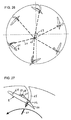
- FIG. 19 , FIG. 19A and FIG. 19B show an embodiment of an aircraft with a system of oppositely rotating cross-flow rotors with a common rotary axis;
- FIG. 20 shows a schematic view of an aircraft in accordance with the invention with an arrangement of a surveillance device which is flexibly linked to the aircraft;
- FIG. 21 shows a further embodiment of the invention in a representation from the front
- FIG. 22 shows the embodiment of FIG. 21 from above
- FIG. 23 shows the embodiment of FIG. 21 in an axonometric view
- FIG. 24 shows a further embodiment of the invention in a side view
- FIG. 25 shows the embodiment of FIG. 24 from the front
- FIG. 26 shows a schematic representation to explain how the rotor blades are triggered
- FIG. 27 shows a detail of FIG. 26 .
- the aircraft according to FIG. 1 to FIG. 6 consists of a fuselage 1 with a longitudinal axis 1 a and of four lifting bodies 2 , 3 , 4 and 5 which are arranged parallel to said longitudinal axis 1 a in a preferred manner above the center-of-gravity position and which are protected by a side protection means 6 against collision with a solid obstruction.
- a horizontal tail unit 11 and a rudder unit 10 there are in the known manner a horizontal tail unit 11 and a rudder unit 10 , and preferably also the drive unit such as one or two gas turbines and the transmission and additional drive units (not shown here in closer detail) which are configured here as by-pass propulsive units which provide the aircraft with a high cruising speed or can support the take-off and landing process in the case of a respective pivoting configuration.
- Skids or similar supports 12 support the aircraft on the ground.
- the rear section of the aircraft is joined with the front section by means of longitudinal struts 13 , 14 , which have a flow-optimized cross-sectional shape or a weight-optimized framework construction.
- a stable construction for a bearing (not shown here) for the lifting bodies 2 , 3 , 4 , 5 in the middle section is provided with the longitudinal struts and the side protection.
- FIG. 2 shows the length ratios, according to which the length of the rotating lifting bodies 2 , 3 , 4 , 5 corresponds to approximately 50%, preferably 30 to 70%, of the total length of the aircraft.
- FIG. 3 shows the lifting bodies 2 , 3 , 4 , 5 with the rotary directions 20 a , 20 b rotating in opposite directions about the rotary axes 7 a , 7 B and the rotor blades 8 required for generating the lifting force.
- Additional drive units (not shown here in closer detail) are provided for a high cruising speed with simultaneous fuel economy.
- these covering skirts can be arranged as compact surfaces 40 a , 40 b (as shown in FIG. 4 for example in the opened state for an optimal effect of the lifting bodies) or as a system of lamellae 40 a ′, 40 b ′, 41 a ′, 41 b ′ which can be set optionally as a closed covering or for an unhindered passage of the air.
- a lifting body 2 , 3 , 4 , 5 substantially consists of a rotary axis 7 , two end disks 2 a - 2 b , 3 a - 3 b , 4 a - 4 b , 5 a - 5 b with the diameter D 23 b and a certain number (preferably 4 to 10) of rotor blades 8 which are arranged movably about a swiveling axis 8 A in the two end disks (e.g. 2 a - 2 b ) and describe a circular path 23 a with the radius R 23 during a full rotation.
- the depth of the rotor blade t 8 e depends on the size of the overall construction and is approximately 30 to 50% of the circular path radius R 23 .
- the length L 8 d of the rotor blade 8 is preferably approximately 25 to 35% of the total length of the aircraft.
- the lifting body rotates at a nominal speed (preferably approximately 750 to 300 1/min) about the rotary axis 7 .
- the rotor blades 8 are set in every momentary position individually with respect to the tangent 23 b of the circular path 23 a with the radius R 23 , so that in the region of the upper and lower extreme position maximum lifting forces can be generated and only flow resistance forces act upon the rotor blade in the two vertical extreme positions.
- the preferred arrangement of the direction of rotation 20 of the lifting bodies in the aircraft is in the opposite direction.
- FIG. 8 shows the flow conditions in closer detail.
- the airfoil theory is relevant as a result of the rotor blade geometry, according to which at a defined relative speed a pressure increase is generated beneath the set rotor blade and a negative pressure above the same.
- the respective force components acting upon the rotor blade are the result of these two pressure components.
- Ambient air is preferably taken in from above 18 A at a respective incidence of the rotor blades relative to tangent 23 b of the circular path 23 a during a fill rotation of the lifting bodies 2 , 3 , 4 , 5 at nominal speed, pressed into the rotating lifting body 18 B, sucked downwardly 19 A and pressed out 19 B.
- An optimal embodiment is shown in FIG. 9 , FIG. 9A and FIG. 9B .
- the rotor blade 8 consists of at least three elements, which are a stable pivoting axis 8 A, a movable rotor blade nose 8 B and a movable rotor blade tip 8 c .
- the rotor blade nose 8 B is swivellable about the angle ⁇ 21 a , preferably by +/ ⁇ 3° to 10° relative to the tangent of the circular path 23 a and the rotor blade tip 8 c is swivellable about the angle ⁇ 21 b , preferably by +/ ⁇ 3° to 10° relative to the tangent of the circular path 23 a .
- the rotor blade tip and rotor blade nose are swivellable by >90°, preferably approximately 105°, for the special case of “autorotation”.
- a vertical force component Fa 22 can be generated in the direction of the rotary axis 7 of the lifting body when at a nominal speed in the up-per extreme position the rotor blade nose 8 B is set at the angle ⁇ 0° and the rotor blade tip with the angle ⁇ >0°, each relating to the tangent direction 23 b of the rotary circular path 23 a , and vice-versa according to FIG.
- FIG. 10 shows in detail the two oppositely driven lifting bodies with the incidences of the rotor blades in different positions, which incidences are optimal for generating a maximum lifting force at nominal speed.
- FIG. 10A (a detail W of FIG. 10 ) shows the angular conditions of the rotor blade nose and the rotor blade tip upon entering the upper circular path after leaving the neutral vertical position.
- FIG. 10B shows the angular conditions of the rotor blade nose and rotor blade tip in the upper extreme position of the circular path.
- FIG. 10C shows the angular conditions of the rotor blade nose and rotor blade tip in the upper circular path prior to the entrance in the neutral vertical position.
- FIG. 10D shows the angular conditions of the rotor blade nose and rotor blade tip in the lower extreme position of the circular path.
- a stable equilibrium position in FIG. 11 , FIG. 12A and FIG. 12B in the air is pro-vided in such a way that every single lifting body 2 , 3 , 4 , 5 can generate individual lifting forces A 1 through A 4 35 a , 35 b , 35 c and 35 d and thus an equilibrium state relative to the overall center of mass S 32 of the overall mass m 33 and to the bulk centers of mass 32 a of the partial mass of cockpit m 1 33 a , with the partial center-of-gravity distance s 1 34 a , and 32 b of the partial mass of the rear region of the aircraft m 2 33 b , with the partial center-of-gravity distance s 2 34 b , and the lateral center-of-gravity distance s 3 34 c of the overall center of mass S 32 of the overall mass m 33 can be produced in each situation. This allows responding at all times to any changing equilibrium position.
- a transition from a hovering state to a slow forward movement or rearward movement is thus enabled in such a way that the aircraft assumes an inclined position ( FIG. 13 ) and a force component 35 a ′, 35 b ′ can be derived from the resulting lifting force 35 a , 35 b of the lifting bodies, which force component allows a forward or rearward acceleration, whereas the vertical force component 35 a ′′, 35 b ′′ continues to keep the aircraft vertically in the equilibrium.
- FIG. 14 shows a transversal movement with the speed v x 36 which is achieved in such a way that according to FIG. 14A the rotor blades in the position of vertical extreme position are brought to a respective inclined position 21 , so that air is sucked in from one direction 18 A and is pressed out 19 B virtually transversally through the aircraft.
- the airfoil theory is applicable in this case too.
- FIG. 14B shows the rotor blade position in a neutral position, whereas according to the rotor blade incidence according to FIG.
- a force component Fq 22 would act upon the aircraft away from the rotary axis and would have a movement with the speed v x 36 from the right to the left.
- a force component Fq 22 would act upon the aircraft in the opposite direction, in the direction of the rotary axis, and would lead to a movement with the speed v x 36 from the left to the right.
- a rotary movement 36 a in the hovering state about the vertical axis 1 b of the aircraft clockwise or counter-clockwise can be achieved by paired opposite generation of the force component Fq 22 in the forward and rearward region of the lifting body according to FIG. 15 .
- FIG. 16A shows a neutral position of the rotor blade (sectional view II-II of FIG. 16 ), as is obtained in the case of a displacement in opposite direction of the two ends of the rotor blade according to FIG. 16B (sectional view I-I of FIG. 16 ) and FIG.
- FIG. 16C sectional view III-III of FIG. 16 .
- this allows correcting different center-of-gravity positions during the flight, performing forward and rearward movements with low flight speed and rotary movements about the vertical axis.
- FIG. 17 shows the respective angles of incidence ⁇ 21 of the rotor blades and the relative air flow 41 and the direction of rotation 20 of the lifting bodies when the aircraft drops with the speed of descent 40 in free fall in the vertical direction.
- FIG. 18 A further embodiment of an aircraft with two lifting bodies 2 , 3 rotating in opposite directions is shown in FIG. 18 .
- FIG. 18A shows a side view and FIG. 18B shows a front view.
- the two lifting bodies rotating in the opposite direction are arranged behind one another along the central axis of the aircraft along a common rotary axis.
- FIG. 18C shows a sectional view I-I of FIG. 18A , which show the bearing of the rotary axis of the lifting bodies 2 , 3 and the lateral protective covering.
- FIG. 18D shows the sectional view II-II of FIG. 18A
- FIG. 18E shows the sectional view III-III of FIG.
- FIG. 18A which show the arrangement and direction of rotation of the lifting bodies arranged behind one another, in the representation for a conventional hovering state or ascending flight.
- FIG. 18F shows the sectional view II-II of FIG. 18A
- FIG. 18G shows the sectional view III-III of FIG. 18A in the position of the rotor blades for achieving autorotation in free descent after failure of one drive unit for example.
- FIG. 19 shows a further embodiment of an aircraft which is suitable for vertical take-off and landing, provided with lifting bodies 36 , 37 , 38 , 39 however which are arranged as cross-flow rotors.
- FIG. 19A shows the top view of such an aircraft and
- FIG. 19B shows a representation according to sectional view I-I of FIG. 19 .
- so-called cross-flow rotors are in use which are provided with external flow guide devices 6 which are arranged in a respectively adjustable way and thus allow achieving a virtually unlimited maneuverability (forward movement, backward movement, transversal movement, rotary movement about the vertical axis).
- lifting bodies 36 , 37 , 38 , 39 which are configured as cross-flow rotors, each consist of two round end disks which carry a plurality of rotor wings 36 a , 37 a and rotate about a rotary axis.
- an inner cross-flow rotor 37 with opposite direction of rotation is inserted in an external cross-flow rotor 36 each for increasing the flow efficiency.
- a unit designated as a surveillance device 43 radar, optical sensor
- a surveillance device 43 can be provided in accordance with FIG. 20 above the aircraft, which surveillance device, when the aircraft is in the hovering state, can be brought vertically upwardly by means of a flexible connection 44 and can thereafter be retracted again.
- the aircraft of FIG. 21 consists of a fuselage 1 with a longitudinal axis 1 a and two cross-flow rotors 2 and 3 which are arranged above said longitudinal axis 1 a .
- a horizontal tail unit 11 In the rear section of the fuselage there are in the known manner a horizontal tail unit 11 and a rudder unit 10 .
- Skids 46 support the aircraft on the ground.
- Two by-pass propulsive units 47 are provided behind the cross-flow rotors 2 , 3 in the region of the tailplane 4 , 5 in order to produce the respective thrust.
- FIG. 22 shows that the length L 1 of the cross-flow rotors 2 , 3 corresponds to approximately 50% of the length L of the entire aircraft.
- FIG. 25 shows the structure of the aircraft on an enlarged scale in a sectional view.
- the rotors 2 , 3 comprise a plurality of blades 8 which are arranged along the circumference.
- the rotors 2 , 3 are each covered on the circumference by a first guide surface 49 and a second guide surface 50 .
- the first guide surface 49 is configured as a part of the outside surface of the fuselage 1
- the second guide surface 50 is configured as a flow guide plate.
- the upper open region of the rotors 2 , 3 is thus used as an air intake opening 54
- the lower open region is used as an air outlet opening 55 .
- the impulse of the downwardly ejected air quantities leads in total to a lifting force for the aircraft, which is represented by arrow 56 and which is sufficient, in the case of a respective configuration, to lift the aircraft from the ground.
- Adjustable guide blades 17 are provided below the rotors 2 , 3 , which in the embodiments of FIG. 24 consist of several segments 17 a , 17 B, 17 c which can be pivoted independent from each other about an axis parallel to the longitudinal axis of the aircraft. As a result, a rotation of the aircraft about a vertical axis 1 b can be effected by the guide blades 17 . It can be seen that the guide blades 17 which are arranged below the air outlet openings are able to change the direction of the air jets along the arrows 53 . In the position as shown in FIG. 6 , a force component to backboard is generated by pivoting the movable guide blades 17 , which is indicated by the arrow 56 . Guide blades 58 can be used within the cross-flow rotors for improved guidance of the air flow. The guide blades 58 can be provided with a movable configuration, which improves the maneuverability at high efficiency.
- the drive of the cross-flow rotors 2 , 3 can occur in principle by piston engines, but is preferably carried out by gas turbines, which is not shown in the drawings.
- FIG. 26 shows that the individual rotor blades 8 are arranged in a pivoting way about a pivot 61 via a tow-bar.
- the tow-bars 60 are held in a common star point 62 which can be displaced relative to the axis 63 at will. An overall flow in any direction can thus be set.
- the rotor blades 8 are guided in pins 64 in connecting links 65 in order to guarantee respective stability.
- FIG. 27 shows that an end region 66 of the rotor blade 8 is separately adjustable.
- a lever 67 connected with the end region 66 comprises a pin 68 which is guided in a second connecting link 69 , so that the rotor blade 8 assumes an asymmetric airfoil profile, which increases the conveying output and the efficiency.
- the stronger the incidence of the rotor blade 8 the stronger the additional incidence of the end region 66 and thus the overall profiling of the rotor blade 8 .
- the present invention describes an aircraft which offers the possibility of vertical take-off and vertical landing, allows a virtually unlimited maneuverability in the hovering state, offers a high cruising speed with simultaneous fuel economy, al-lows the pilot a secure exit from the aircraft if required, and houses a flexibly arranged surveillance device above the aircraft.
Landscapes
- Engineering & Computer Science (AREA)
- Aviation & Aerospace Engineering (AREA)
- Toys (AREA)
- Radio Relay Systems (AREA)
- Details Of Aerials (AREA)
- Fluid-Pressure Circuits (AREA)
- Transmission Devices (AREA)
- Application Of Or Painting With Fluid Materials (AREA)
- Other Liquid Machine Or Engine Such As Wave Power Use (AREA)
- Percussion Or Vibration Massage (AREA)
- Containers And Packaging Bodies Having A Special Means To Remove Contents (AREA)
- Refuse Collection And Transfer (AREA)
Applications Claiming Priority (5)
| Application Number | Priority Date | Filing Date | Title |
|---|---|---|---|
| AT0189502A AT411988B (de) | 2002-12-18 | 2002-12-18 | Fluggerät |
| ATA1895/2002 | 2002-12-18 | ||
| ATA673/2003 | 2003-05-05 | ||
| AT6732003A AT501864B1 (de) | 2003-05-05 | 2003-05-05 | Fluggerät |
| PCT/AT2003/000371 WO2004054875A1 (de) | 2002-12-18 | 2003-12-18 | Fluggerät |
Related Parent Applications (1)
| Application Number | Title | Priority Date | Filing Date |
|---|---|---|---|
| PCT/AT2003/000371 Continuation-In-Part WO2004054875A1 (de) | 2002-12-18 | 2003-12-18 | Fluggerät |
Publications (2)
| Publication Number | Publication Date |
|---|---|
| US20050274843A1 US20050274843A1 (en) | 2005-12-15 |
| US7735773B2 true US7735773B2 (en) | 2010-06-15 |
Family
ID=32597784
Family Applications (1)
| Application Number | Title | Priority Date | Filing Date |
|---|---|---|---|
| US11/157,031 Expired - Fee Related US7735773B2 (en) | 2002-12-18 | 2005-06-20 | Aircraft |
Country Status (13)
| Country | Link |
|---|---|
| US (1) | US7735773B2 (de) |
| EP (1) | EP1575828B1 (de) |
| KR (1) | KR101152703B1 (de) |
| CN (1) | CN1738743B (de) |
| AT (1) | ATE402071T1 (de) |
| AU (1) | AU2003287751A1 (de) |
| CA (1) | CA2510225C (de) |
| DE (1) | DE50310211D1 (de) |
| DK (1) | DK1575828T3 (de) |
| ES (1) | ES2311115T3 (de) |
| PT (1) | PT1575828E (de) |
| SI (1) | SI1575828T1 (de) |
| WO (1) | WO2004054875A1 (de) |
Cited By (7)
| Publication number | Priority date | Publication date | Assignee | Title |
|---|---|---|---|---|
| US20130119186A1 (en) * | 2010-07-26 | 2013-05-16 | Siemens Aktiengesellschaft | Torque compensation for a helicopter |
| US9061762B2 (en) | 2012-06-11 | 2015-06-23 | James W Vetter | Multi-orientation, advanced vertical agility, variable-environment vehicle |
| US9102397B2 (en) | 2011-12-20 | 2015-08-11 | General Electric Company | Airfoils including tip profile for noise reduction and method for fabricating same |
| US20190061925A1 (en) * | 2017-08-28 | 2019-02-28 | Bell Helicopter Textron Inc. | Cargo Transportation System having Perimeter Propulsion |
| RU2720699C1 (ru) * | 2019-04-09 | 2020-05-12 | Виктор Петрович Мельников | Способ работы крыльчатого движителя и устройство для его осуществления |
| US11325697B1 (en) * | 2016-07-18 | 2022-05-10 | Franklin Y. K. Chen | VTOL flying wing and flying wing aircraft |
| US11511855B2 (en) * | 2020-04-22 | 2022-11-29 | Dongxiu LU | Ornithopter aircraft |
Families Citing this family (12)
| Publication number | Priority date | Publication date | Assignee | Title |
|---|---|---|---|---|
| US8398015B2 (en) | 2004-07-06 | 2013-03-19 | Sean O'Connor | Aircraft that can fly horizontally and vertically |
| US7370828B2 (en) * | 2005-05-04 | 2008-05-13 | X Blade Systems Lp | Rotary wing aircraft |
| US8382434B2 (en) * | 2006-09-11 | 2013-02-26 | Phillip Createman | Fluid-propelling device having collapsible counter-rotating impellers |
| CN103587702A (zh) * | 2012-08-14 | 2014-02-19 | 林彦良 | 横流扇飞行装置 |
| CN104276284B (zh) * | 2014-10-08 | 2016-04-20 | 中国航空工业集团公司西安飞机设计研究所 | 一种串列式扇翼飞行器布局 |
| US10421541B2 (en) * | 2016-08-10 | 2019-09-24 | Bell Helicopter Textron Inc. | Aircraft with tilting cross-flow fan wings |
| US10377480B2 (en) * | 2016-08-10 | 2019-08-13 | Bell Helicopter Textron Inc. | Apparatus and method for directing thrust from tilting cross-flow fan wings on an aircraft |
| US10479495B2 (en) * | 2016-08-10 | 2019-11-19 | Bell Helicopter Textron Inc. | Aircraft tail with cross-flow fan systems |
| CN109515704B (zh) * | 2018-12-18 | 2024-04-16 | 南京航空航天大学 | 基于摆线桨技术的涵道卷流旋翼飞行器 |
| DE102021004136B4 (de) | 2021-08-09 | 2023-03-09 | Friedrich B. Grimm | Vorrichtung für ein Drehflügelfahrzeug oder für eine Drehflügelturbine |
| CN114313259B (zh) * | 2021-12-30 | 2024-09-06 | 中国人民解放军总参谋部第六十研究所 | 一种纵向滚翼单元及基于该纵向滚翼单元的纵向滚翼飞行器 |
| CN114435591B (zh) * | 2022-02-23 | 2023-05-16 | 陈华 | 一种滚翼飞行器 |
Citations (16)
| Publication number | Priority date | Publication date | Assignee | Title |
|---|---|---|---|---|
| US1304187A (en) * | 1919-05-20 | Aeroplane | ||
| US1532902A (en) * | 1924-12-27 | 1925-04-07 | Immers Jean Baptiste | Aeroplane |
| US1567531A (en) * | 1923-03-24 | 1925-12-29 | Magni Piero | Variable fluido-dynamic wings such as for aeroplanes |
| US1631861A (en) * | 1926-06-25 | 1927-06-07 | Hanschke Adelheid | Flying machine |
| US2034761A (en) * | 1933-06-26 | 1936-03-24 | Archibald M King | Lifting device for aircraft |
| US2037377A (en) * | 1929-01-14 | 1936-04-14 | Albert B Gardner | Construction for aircraft |
| US3361386A (en) | 1965-08-09 | 1968-01-02 | Gene W. Smith | Vertical or short take-off and landing aircraft |
| US4519562A (en) | 1981-07-27 | 1985-05-28 | Willis William M | Aircraft |
| US5100080A (en) * | 1989-04-17 | 1992-03-31 | Pierre Servanty | Rotor for developing sustaining and propelling forces in a fluid, steering process, and aircraft equipped with such rotor |
| US5320310A (en) * | 1993-02-24 | 1994-06-14 | The Windward Projects | Articulated wing mechanism |
| WO1998007622A1 (en) | 1996-08-20 | 1998-02-26 | Patrick Peebles | Improvements in or relating to fluid dynamic lift generation |
| DE19634522A1 (de) | 1996-08-27 | 1998-03-05 | Richard Jelke | Querstromventilator mit beweglichen Profilschaufeln, die sich durch den Luftstrom einstellen, für den Antrieb für Flugzeuge |
| US6007021A (en) * | 1997-11-18 | 1999-12-28 | Tsepenyuk; Mikhail | Flying apparatus for a vertical take off and landing |
| US6016992A (en) | 1997-04-18 | 2000-01-25 | Kolacny; Gordon | STOL aircraft |
| US6261051B1 (en) | 1998-09-02 | 2001-07-17 | Gordon A. Kolacny | Fan duct combination unit |
| US6845940B2 (en) * | 2000-09-28 | 2005-01-25 | Kikushiro Hashimoto | Lift generator by continuously rotating impeller |
Family Cites Families (4)
| Publication number | Priority date | Publication date | Assignee | Title |
|---|---|---|---|---|
| US1761053A (en) * | 1928-06-11 | 1930-06-03 | Ingemar K Rystedt | Airplane |
| GB885663A (en) * | 1956-12-07 | 1961-12-28 | Laing Nikolaus | Improvement relating to aircraft |
| US3801047A (en) * | 1972-02-04 | 1974-04-02 | Wendros Co | Omnidirectional aircraft |
| JPH06502364A (ja) * | 1990-07-25 | 1994-03-17 | サドレアー・ヴィートール・エアクラフト・カンパニー・プロプライエタリー・リミテッド | Vtol航空機のための推進ユニット |
-
2003
- 2003-12-18 AT AT03779547T patent/ATE402071T1/de active
- 2003-12-18 DE DE50310211T patent/DE50310211D1/de not_active Expired - Lifetime
- 2003-12-18 SI SI200331405T patent/SI1575828T1/sl unknown
- 2003-12-18 ES ES03779547T patent/ES2311115T3/es not_active Expired - Lifetime
- 2003-12-18 PT PT03779547T patent/PT1575828E/pt unknown
- 2003-12-18 AU AU2003287751A patent/AU2003287751A1/en not_active Abandoned
- 2003-12-18 EP EP03779547A patent/EP1575828B1/de not_active Expired - Lifetime
- 2003-12-18 CN CN2003801055548A patent/CN1738743B/zh not_active Expired - Fee Related
- 2003-12-18 DK DK03779547T patent/DK1575828T3/da active
- 2003-12-18 WO PCT/AT2003/000371 patent/WO2004054875A1/de not_active Ceased
- 2003-12-18 CA CA2510225A patent/CA2510225C/en not_active Expired - Fee Related
- 2003-12-18 KR KR1020057011436A patent/KR101152703B1/ko not_active Expired - Fee Related
-
2005
- 2005-06-20 US US11/157,031 patent/US7735773B2/en not_active Expired - Fee Related
Patent Citations (17)
| Publication number | Priority date | Publication date | Assignee | Title |
|---|---|---|---|---|
| US1304187A (en) * | 1919-05-20 | Aeroplane | ||
| US1567531A (en) * | 1923-03-24 | 1925-12-29 | Magni Piero | Variable fluido-dynamic wings such as for aeroplanes |
| US1532902A (en) * | 1924-12-27 | 1925-04-07 | Immers Jean Baptiste | Aeroplane |
| US1631861A (en) * | 1926-06-25 | 1927-06-07 | Hanschke Adelheid | Flying machine |
| US2037377A (en) * | 1929-01-14 | 1936-04-14 | Albert B Gardner | Construction for aircraft |
| US2034761A (en) * | 1933-06-26 | 1936-03-24 | Archibald M King | Lifting device for aircraft |
| US3361386A (en) | 1965-08-09 | 1968-01-02 | Gene W. Smith | Vertical or short take-off and landing aircraft |
| US4519562A (en) | 1981-07-27 | 1985-05-28 | Willis William M | Aircraft |
| US5100080A (en) * | 1989-04-17 | 1992-03-31 | Pierre Servanty | Rotor for developing sustaining and propelling forces in a fluid, steering process, and aircraft equipped with such rotor |
| US5320310A (en) * | 1993-02-24 | 1994-06-14 | The Windward Projects | Articulated wing mechanism |
| WO1998007622A1 (en) | 1996-08-20 | 1998-02-26 | Patrick Peebles | Improvements in or relating to fluid dynamic lift generation |
| US6231004B1 (en) | 1996-08-20 | 2001-05-15 | Patrick Peebles | Fluid dynamic lift generation |
| DE19634522A1 (de) | 1996-08-27 | 1998-03-05 | Richard Jelke | Querstromventilator mit beweglichen Profilschaufeln, die sich durch den Luftstrom einstellen, für den Antrieb für Flugzeuge |
| US6016992A (en) | 1997-04-18 | 2000-01-25 | Kolacny; Gordon | STOL aircraft |
| US6007021A (en) * | 1997-11-18 | 1999-12-28 | Tsepenyuk; Mikhail | Flying apparatus for a vertical take off and landing |
| US6261051B1 (en) | 1998-09-02 | 2001-07-17 | Gordon A. Kolacny | Fan duct combination unit |
| US6845940B2 (en) * | 2000-09-28 | 2005-01-25 | Kikushiro Hashimoto | Lift generator by continuously rotating impeller |
Cited By (11)
| Publication number | Priority date | Publication date | Assignee | Title |
|---|---|---|---|---|
| US20130119186A1 (en) * | 2010-07-26 | 2013-05-16 | Siemens Aktiengesellschaft | Torque compensation for a helicopter |
| US9452832B2 (en) * | 2010-07-26 | 2016-09-27 | Siemens Aktiengesellschaft | Torque compensation for a helicopter |
| US9102397B2 (en) | 2011-12-20 | 2015-08-11 | General Electric Company | Airfoils including tip profile for noise reduction and method for fabricating same |
| US9061762B2 (en) | 2012-06-11 | 2015-06-23 | James W Vetter | Multi-orientation, advanced vertical agility, variable-environment vehicle |
| US9315266B2 (en) | 2012-06-11 | 2016-04-19 | James W Vetter | Multi-orientation, advanced vertical agility, variable-environment vehicle |
| US9580171B2 (en) | 2012-06-11 | 2017-02-28 | James W Vetter | Multi-orientation, advanced vertical agility, variable-environment vehicle |
| US11325697B1 (en) * | 2016-07-18 | 2022-05-10 | Franklin Y. K. Chen | VTOL flying wing and flying wing aircraft |
| US20190061925A1 (en) * | 2017-08-28 | 2019-02-28 | Bell Helicopter Textron Inc. | Cargo Transportation System having Perimeter Propulsion |
| US10814967B2 (en) * | 2017-08-28 | 2020-10-27 | Textron Innovations Inc. | Cargo transportation system having perimeter propulsion |
| RU2720699C1 (ru) * | 2019-04-09 | 2020-05-12 | Виктор Петрович Мельников | Способ работы крыльчатого движителя и устройство для его осуществления |
| US11511855B2 (en) * | 2020-04-22 | 2022-11-29 | Dongxiu LU | Ornithopter aircraft |
Also Published As
| Publication number | Publication date |
|---|---|
| DE50310211D1 (de) | 2008-09-04 |
| KR101152703B1 (ko) | 2012-06-15 |
| SI1575828T1 (sl) | 2009-02-28 |
| AU2003287751A1 (en) | 2004-07-09 |
| CN1738743A (zh) | 2006-02-22 |
| CA2510225C (en) | 2011-04-12 |
| WO2004054875A1 (de) | 2004-07-01 |
| US20050274843A1 (en) | 2005-12-15 |
| CA2510225A1 (en) | 2004-07-01 |
| KR20050098232A (ko) | 2005-10-11 |
| PT1575828E (pt) | 2008-12-09 |
| EP1575828B1 (de) | 2008-07-23 |
| ES2311115T3 (es) | 2009-02-01 |
| CN1738743B (zh) | 2010-10-27 |
| ATE402071T1 (de) | 2008-08-15 |
| DK1575828T3 (da) | 2008-12-01 |
| EP1575828A1 (de) | 2005-09-21 |
Similar Documents
| Publication | Publication Date | Title |
|---|---|---|
| US7735773B2 (en) | Aircraft | |
| EP1704089B1 (de) | Kipprotorflugzeug | |
| US5064143A (en) | Aircraft, having a pair of counter rotating rotors | |
| US6655631B2 (en) | Personal hoverplane with four tiltmotors | |
| US7410122B2 (en) | VTOL UAV with lift fans in joined wings | |
| CN111498109B (zh) | 垂直起降的飞行器 | |
| US20190291860A1 (en) | Vertical take-off and landing aircraft and control method | |
| US4071207A (en) | Vertical take-off aircraft | |
| US20170174342A1 (en) | Vertical Takeoff Aircraft and Method | |
| US8857755B2 (en) | Vertical/short take-off and landing passenger aircraft | |
| US20110001020A1 (en) | Quad tilt rotor aerial vehicle with stoppable rotors | |
| US3142455A (en) | Rotary vertical take-off and landing aircraft | |
| CN112238939B (zh) | 新构型倾转旋翼飞行器及其飞行控制方法 | |
| US20160236775A1 (en) | Vertical takeoff and landing aircraft | |
| EP0882647B1 (de) | Extrem kurze Start- und Landestrecke eines Flugzeugs durch Verwendung einer mehrachsigen Schubvektorsteuerung | |
| CN101027214A (zh) | 旋翼飞行器 | |
| EP0250555A1 (de) | Zusatzdrehmomentausgleichsantriebssystem für hubschrauber | |
| EP4279390B1 (de) | Rumpf für ein senkrechtstarter und landeflugzeug | |
| CN105905294A (zh) | 垂直起降固定翼无人机 | |
| CN108263594A (zh) | 一种无叶风扇动力垂直起降无人机 | |
| WO2004031876A1 (en) | Flight control system for vtol aircraft | |
| WO2022271401A2 (en) | Methods of vertical take-off/landing and horizontal straight flight of aircraft and aircraft for implementation | |
| US20220380035A1 (en) | Methods of vertical take-off/landing and horizontal straight flight of aircraft and aircraft for implementation | |
| RU213749U1 (ru) | Летающая платформа-квадрокоптер | |
| KR20240124062A (ko) | 가변익 드론 |
Legal Events
| Date | Code | Title | Description |
|---|---|---|---|
| AS | Assignment |
Owner name: IAT 21 INNOVATIVE AERONAUTICS TECHNOLOGIES GMBH,AU Free format text: ASSIGNMENT OF ASSIGNORS INTEREST;ASSIGNOR:SCHWAIGER, MEINHARD;REEL/FRAME:024254/0379 Effective date: 20050615 |
|
| STCF | Information on status: patent grant |
Free format text: PATENTED CASE |
|
| FPAY | Fee payment |
Year of fee payment: 4 |
|
| MAFP | Maintenance fee payment |
Free format text: PAYMENT OF MAINTENANCE FEE, 8TH YR, SMALL ENTITY (ORIGINAL EVENT CODE: M2552) Year of fee payment: 8 |
|
| FEPP | Fee payment procedure |
Free format text: MAINTENANCE FEE REMINDER MAILED (ORIGINAL EVENT CODE: REM.); ENTITY STATUS OF PATENT OWNER: SMALL ENTITY |
|
| LAPS | Lapse for failure to pay maintenance fees |
Free format text: PATENT EXPIRED FOR FAILURE TO PAY MAINTENANCE FEES (ORIGINAL EVENT CODE: EXP.); ENTITY STATUS OF PATENT OWNER: SMALL ENTITY |
|
| STCH | Information on status: patent discontinuation |
Free format text: PATENT EXPIRED DUE TO NONPAYMENT OF MAINTENANCE FEES UNDER 37 CFR 1.362 |
|
| FP | Lapsed due to failure to pay maintenance fee |
Effective date: 20220615 |