US7744348B2 - Method of producing a hot gas component of a turbomachine including an embedded channel - Google Patents
Method of producing a hot gas component of a turbomachine including an embedded channel Download PDFInfo
- Publication number
- US7744348B2 US7744348B2 US11/763,610 US76361007A US7744348B2 US 7744348 B2 US7744348 B2 US 7744348B2 US 76361007 A US76361007 A US 76361007A US 7744348 B2 US7744348 B2 US 7744348B2
- Authority
- US
- United States
- Prior art keywords
- coating
- basic body
- cooling
- component
- passage
- Prior art date
- Legal status (The legal status is an assumption and is not a legal conclusion. Google has not performed a legal analysis and makes no representation as to the accuracy of the status listed.)
- Expired - Lifetime, expires
Links
Images


Classifications
-
- C—CHEMISTRY; METALLURGY
- C30—CRYSTAL GROWTH
- C30B—SINGLE-CRYSTAL GROWTH; UNIDIRECTIONAL SOLIDIFICATION OF EUTECTIC MATERIAL OR UNIDIRECTIONAL DEMIXING OF EUTECTOID MATERIAL; REFINING BY ZONE-MELTING OF MATERIAL; PRODUCTION OF A HOMOGENEOUS POLYCRYSTALLINE MATERIAL WITH DEFINED STRUCTURE; SINGLE CRYSTALS OR HOMOGENEOUS POLYCRYSTALLINE MATERIAL WITH DEFINED STRUCTURE; AFTER-TREATMENT OF SINGLE CRYSTALS OR A HOMOGENEOUS POLYCRYSTALLINE MATERIAL WITH DEFINED STRUCTURE; APPARATUS THEREFOR
- C30B29/00—Single crystals or homogeneous polycrystalline material with defined structure characterised by the material or by their shape
- C30B29/10—Inorganic compounds or compositions
- C30B29/52—Alloys
-
- B—PERFORMING OPERATIONS; TRANSPORTING
- B23—MACHINE TOOLS; METAL-WORKING NOT OTHERWISE PROVIDED FOR
- B23P—METAL-WORKING NOT OTHERWISE PROVIDED FOR; COMBINED OPERATIONS; UNIVERSAL MACHINE TOOLS
- B23P15/00—Making specific metal objects by operations not covered by a single other subclass or a group in this subclass
- B23P15/02—Making specific metal objects by operations not covered by a single other subclass or a group in this subclass turbine or like blades from one piece
-
- B—PERFORMING OPERATIONS; TRANSPORTING
- B23—MACHINE TOOLS; METAL-WORKING NOT OTHERWISE PROVIDED FOR
- B23P—METAL-WORKING NOT OTHERWISE PROVIDED FOR; COMBINED OPERATIONS; UNIVERSAL MACHINE TOOLS
- B23P15/00—Making specific metal objects by operations not covered by a single other subclass or a group in this subclass
- B23P15/04—Making specific metal objects by operations not covered by a single other subclass or a group in this subclass turbine or like blades from several pieces
-
- C—CHEMISTRY; METALLURGY
- C30—CRYSTAL GROWTH
- C30B—SINGLE-CRYSTAL GROWTH; UNIDIRECTIONAL SOLIDIFICATION OF EUTECTIC MATERIAL OR UNIDIRECTIONAL DEMIXING OF EUTECTOID MATERIAL; REFINING BY ZONE-MELTING OF MATERIAL; PRODUCTION OF A HOMOGENEOUS POLYCRYSTALLINE MATERIAL WITH DEFINED STRUCTURE; SINGLE CRYSTALS OR HOMOGENEOUS POLYCRYSTALLINE MATERIAL WITH DEFINED STRUCTURE; AFTER-TREATMENT OF SINGLE CRYSTALS OR A HOMOGENEOUS POLYCRYSTALLINE MATERIAL WITH DEFINED STRUCTURE; APPARATUS THEREFOR
- C30B13/00—Single-crystal growth by zone-melting; Refining by zone-melting
- C30B13/16—Heating of the molten zone
- C30B13/22—Heating of the molten zone by irradiation or electric discharge
- C30B13/24—Heating of the molten zone by irradiation or electric discharge using electromagnetic waves
-
- F—MECHANICAL ENGINEERING; LIGHTING; HEATING; WEAPONS; BLASTING
- F01—MACHINES OR ENGINES IN GENERAL; ENGINE PLANTS IN GENERAL; STEAM ENGINES
- F01D—NON-POSITIVE DISPLACEMENT MACHINES OR ENGINES, e.g. STEAM TURBINES
- F01D5/00—Blades; Blade-carrying members; Heating, heat-insulating, cooling or antivibration means on the blades or the members
- F01D5/12—Blades
- F01D5/14—Form or construction
- F01D5/18—Hollow blades, i.e. blades with cooling or heating channels or cavities; Heating, heat-insulating or cooling means on blades
- F01D5/187—Convection cooling
Definitions
- the present invention relates to a component, especially a hot gas component of a turbomachine, with at least one passage which is embedded in an outer wall of the component and basically extends parallel to and close to the surface of the component, which passage is especially to serve for intake of a cooling medium.
- the invention relates to a method for producing at least one such passage in a component.
- Modern turbomachines like, for example, gas turbines, are exposed to high loads during operation. They are often operated with hot gases at more than 800° C., and at the same time are subjected to high mechanical loads.
- the increase of turbine output capacity during the last decades is fundamentally based on two improvements.
- continuously new efficient materials were developed, like, for example, monocrystal alloys, as a result of which the load capacity of the components which lie in the flow cross section of the hot gases could be increased, and on the other hand, cooling systems and temperature protective coatings, which were improved time and again, were developed, which resulted in an increase of the turbine inlet temperatures, and, as a result, an increase of the turbine output.
- Monocrystal alloys like, for example, CMSX2, CMSX4, or MK4, have especially led to an appreciable reduction of the temperature sensitivity, and, as a result, to appreciably improved mechanical properties at high temperatures.
- the output capacity of gas turbines is directly coupled with the inlet temperature of the hot gases, for years a continuous increase of the hot gas temperature has been noted, so that especially in the first turbine stages gas temperatures are already achieved which exceed the melting temperatures of the alloys which are used there.
- complex internal cooling systems were developed, which cool the components which lie in the flow cross section in such a way that these lie below a critical temperature limit at which the components would be damaged. In this case, it is common to all cooling systems that a compromise has to be made between the desired cooling effect, the amount of cooling air which is available, and the costs.
- the cooling air which is required for cooling is generally delivered from a compressor and, by means of an internal cooling system, is distributed to the components which are to be cooled.
- the components have internal cooling passages, for example, which extend in serpentine-like fashion and which interact in a communicating manner with a multiplicity of discharge openings on a surface of the component, as a result of which a film cooling or transpiration cooling is created.
- An especially effective cooling is achieved in this case, if the wall which is to be cooled has a wall thickness which is as small as possible (EP 0 964 981).
- Another efficient, convective cooling system is effected by means of coolable wall structures, as it is proposed, for example, in EP 1 462 611, EP 1 462 612, and EP 1 462 613.
- the walls of the hot gas components are equipped with a network of cooling passages.
- such internal cooling passages are exceptionally complicated to produce in the manufacturing process and, therefore, are disproportionately expensive.
- a method for producing or repairing cooling passages, which are close to the surface, in a hot gas component of the gas turbine has become known, which is basically based on a profile being applied to a basic body of this component, which profile corresponds to the later structure of the cooling passages.
- This can be carried out either in the way by a thermally stable filling material in a corresponding structure being applied to the surface of the basic body, or by this structure first being mechanically machined from out of the surface of the basic body and the cavities which result from it then being filled with the thermally stable filling material.
- a coating material is applied by means of a coating method, at least in the region of the cooling structure.
- the cooling passages are opened by means of subsequent removal of the filling material.
- cooling passage network in a component of a turbomachine, which on one hand brings about an efficient cooling of the component on account of its position which is arranged just beneath the surface of the outer wall, and which on the other hand can dispense with costly casting molds and results in lower scrap rates.
- the cooling passages, which are embedded in the outer wall of the component can generally also be combined with other cooling strategies, like, for example, the transpiration cooling which is described above, as a result of which a high flexibility and a broadened application spectrum can be achieved.
- One of numerous aspect of the present invention is based on making available a component of a turbomachine of the aforementioned type, which especially has an enhanced cooling system with greatly reduced manufacturing cost. Furthermore, another aspect of the present invention is based on making available a method for producing at least one passage which is embedded in an outer wall of such a component.
- Another aspect of the present invention is based first producing in a first step the structure of the cooling medium passages on the surface of the basic body in a component of a turbomachine of the aforementioned type, and, in a further step, applying a coating material while directly bridging the cooling medium passages which are produced, without these being masked with a filling material.
- the cooling passages which are embedded in the outer wall of the component, can generally also be combined with other cooling strategies, like, for example, transpiration cooling which is described above, as result of which an especially high flexibility and a broadened application spectrum can be achieved.
- the basic body expediently has an equidirectional grain structure and/or monocrystal structure.
- Monocrystal structures are spoken of when the building blocks of the crystal, consequently the ions, atoms, or molecules, form a unitary, homogenous crystal lattice.
- a slipping of the grains along the grain boundaries for example as a result of the centrifugal forces which prevail in the turbine, is avoided, since in monocrystals there is only just one single grain which at the same time is the crystal.
- At least one passage communicates with at least one discharge opening which leads to the surface of the component.
- the especially effective cooling system which extends closely beneath the surface is combined with a known film cooling, which by permanent discharge of cooling air through the discharge openings creates a cooling medium film which is distributed over the surface of the component.
- a so-called open cooling system in which permanent cooling medium, as a rule air, from a cooling medium source of relatively high pressure, for example which is branched from the compressor of a gas turbine plant, is directed into the component which is to be cooled through its internal cooling passages up to the discharge openings in the outer wall.
- a passage longitudinal axis is at a distance of less than 3 mm from the surface of the component.
- a width of the cavity, at least in the region of a surface, is expediently less than 1 mm.
- the width is preferably even only 0.2 mm, as a result of which bridging of the cavity width by the applied coating is simplified.
- too great a penetration of the applied coating into the cavity is also avoided, since the two edges or the two cavity walls, as the case may be, have a large surface in comparison to the amount of coating which has penetrated, and, as a result, bring about a quick hardening of the coating.
- the small width of the cavity furthermore, has the advantage that in comparison to cavities with larger width, a close-meshed network of cooling passages can be extended on the surface of the component or of a turbine blade respectively, and, as a result, a more uniform cooling performance or individually better adaptable cooling performance, as the case may be, can be achieved.
- FIG. 1 shows a component of a turbomachine according to the invention, with passages which are made partially visible and embedded in the outer wall of the component,
- FIG. 2 shows a cross section through the component along a cutting plane II-II
- FIG. 3 shows a detailed view of cooling passages which are embedded in the outer wall of the component
- FIG. 4 shows a much enlarged detail of a cross section in the region of the coating which closes off the passage
- FIG. 5 shows a view as in FIG. 4 , however with a previously heated basic body
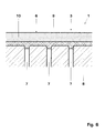
- FIG. 6 shows a view as in FIG. 3 , of another embodiment.
- a component 1 of a turbomachine which apart from that is not shown, has a region 2 which during operation of the turbomachine is flow-washed by hot gases.
- the component 1 can be a blade 3 , stator blade or rotor blade of a gas turbine.
- the blade 3 leads into a blade root 4 , by which the blade is fastened, for example, to a stator or a rotor.
- turbine inlet temperatures which are as high as possible are desired. High turbine inlet temperatures, however, disadvantageously affect the service life of the components 1 which are exposed to hot gas as long as these are not adequately protected.
- monocrystal alloys like, for example, CMSX2, CMSX4, or MK4, which are frequently used in modern machine construction. Crystals, the building blocks of which form a unitary, homogenous crystal lattice, are referred to as monocrystals.
- the blade 3 In addition to the material selection which was mentioned, the blade 3 , furthermore, can be protected against damage by the hot gases by cooling.
- the blade 3 has passages 7 , 7 ′, especially cooling passages, which are embedded at least in one region of an outer wall 5 and which basically extend parallel to the surface 6 of the component 1 or the blade 3 , as the case may be.
- the component 1 has a basic body 8 , which, for example, has a equidirectional graining and at least one coating 9 , for example a connecting layer, which is applied to the basic body 8 on the outer side.
- the passage 7 , 7 ′ in this case is formed on one hand by a cavity which is introduced in the basic body 8 , and on the other hand is closed off towards the surface 6 of the component 1 by the coating 9 .
- the coating 9 on the outside supports a thermal protection layer 10 .
- the coating 9 in this case can be a metal coating which protects the basic body 8 against hot temperature oxidation and temperature corrosion.
- the coating 9 can include the same material as the basic body 8 and/or, for example, can be a MCRALY alloy, wherein M stands for nickel, cobalt, iron, or a combination of these elements.
- the preferably metal coating 9 in this case can have a layer thickness of 100 ⁇ m to 600 ⁇ m.
- the coating 9 fulfills a further function, specifically the provision of an adhesion layer for the temperature/thermal protection layer 10 which is arranged on the coating 9 on the outside.
- the thermal protection layer 10 in this case can be formed from a ceramic material, like, for example, ZrO 2 , and on account of its insulating action reduces the thermal stress for the components which lie beneath it.
- the thermal protection layer 10 can be applied, for example, by a plasma spray process or an electron beam evaporation process.
- FIG. 3 shows a detailed cross section in the region of the surface 6 of the component 1 or surface of the blade 3 , as the case may be, wherein two passages 7 and 7 ′ are exemplarily shown, which differ in their cross section.
- the cooling passages 7 , 7 ′ in this case are embedded in the basic body 8 and have an opening towards the initially uncoated surface of the basic body 8 .
- the openings of the passages 7 and 7 ′ are bridged and closed off by the coating 9 which is arranged in the opening region in each case.
- the coating 9 as shown in FIG.
- passages 7 , 7 ′ can only be arranged in the region of the openings of the passages 7 , 7 ′, or they can cover the basic body 8 along its entire surface, as shown in FIG. 6 . It is also conceivable that at least one passage 7 , 7 ′ communicates with at least one discharge opening, which is not shown, which leads to the surface of the component 1 and as a result creates a film cooling along the surface 6 .
- passages 7 , 7 ′ In order to fully develop the cooling action of the passages 7 , 7 ′, these have to be integrated into a cooling circuit of the turbomachine, so that a through-flow of cooling medium through the passages 7 , 7 ′ can be achieved. It is also conceivable that a plurality of passages 7 , 7 ′ form a communicating passage network, which is shown according to FIG. 3 by a connecting passage 11 which is shown by discontinuous lines. Furthermore, it is necessary for an effective cooling of the blade 3 or the component 1 , as the case may be, that the passages 7 , 7 ′ lie as close as possible to the surface 6 of the component 1 . Therefore, a passage longitudinal axis 12 , which according to FIG. 3 basically extends orthogonally to the illustration plane, is preferably at a distance of less than 3 mm from the surface 6 of the component 1 or the blade 3 , as the case may be.
- a length/diameter ratio of at least one passage 7 , 7 ′ is greater than five. Furthermore, in order to ensure a reliable closing off of the passage 7 , 7 ′ towards the surface 6 of the component 1 , a width of the cavity or the passage 7 , 7 ′, as the case may be, is less than 1 mm, preferably in the region of about 0.2 mm. In this case, different cross sectional shapes of the passages 7 and 7 ′ are shown according to FIG. 3 , wherein the passage 7 tapers in its width towards the surface 6 of the component, while the passage 7 ′ has a constant width.
- FIG. 4 A directly bridged passage 7 is shown in FIG. 4 , wherein the coating 9 in the region of the passage 7 has a pillar-like construction of fine dendrites.
- the orientation of the dendrites in this case is parallel to the orientation of the substrate of the basic body 8 and at the same time epitaxially hardens with the substrate. This is especially advantageous when the component 1 or the blade 3 , as the case may be, is subjected to a cyclic thermal and mechanical stress, as this is the case, for example, in gas turbines.
- FIG. 4 A directly bridged passage 7 is shown in FIG. 4 , wherein the coating 9 in the region of the passage 7 has a pillar-like construction of fine dendrites.
- the orientation of the dendrites in this case is parallel to the orientation of the substrate of the basic body 8 and at the same time epitaxially hardens with the substrate.
- the side edges of the passage 7 which are oriented towards the coating 9 can melt off or melt down, as the case may be, when applying the coating 9 and can then deviate considerably from the original shape, which is shown by a discontinuously drawn line.
- a passage 7 which is produced according to the same method is shown, wherein in this case the structure was modified in an advantageous way, for example by laser melting, after applying the coating 9 .
- the basic body 8 is able to have been preheated, especially by a laser, before the metal forming.
- a preheating temperature for example 1100° C. comes into consideration, as a result of which high temperature gradients inside the interaction zone, and therefore inside a connecting zone between coating 9 and basic body 8 , can be reduced.
- the higher ductility of the base material, as result of heating it, and also the lower temperature gradients contribute to a reduction of a risk of cracks during hardening of the coating 9 .
- a method for producing at least one passage 7 which is embedded in an outer wall 5 of a component 1 of a turbomachine by coating the outer surface 6 , is to be briefly described in the following.
- a passage-like cavity called a passage 7 , 7 ′, is first introduced in the basic body 8 of the component 1 .
- This can be carried out, for example, mechanically and/or electrochemically and/or photochemically and/or by a laser, especially by a short pulse laser.
- a local surface melting of the basic body 8 is carried out, wherein again a laser is also used in this case for melting the basic body 8 .
- the application and melting of a coating 9 is carried out in one working cycle with the melting of the basic body 8 , wherein the coating 9 , the process temperature, and the width of the passage 7 , 7 ′ are matched to each other so that the molten coating material, owing to its surface tension, does not penetrate into the passage 7 , 7 ′. Therefore, no filling material is required for closing off the passage 7 , 7 ′, as this is the case in the production processes according to the prior art.
- a metal powder is used, which in the molten state forms a bridge across the passage 7 , 7 ′ on account of its surface tension and, as a result, closes this off towards the surface 6 of the component 1 .
- the application of the coating 9 to the basic body 8 can be carried out, for example, by plasma spraying and/or by an electron beam evaporation process and/or by a laser.
- a LMF method laser metal forming
- E-LMF method epipitaxial LMF
- a controlled cooling and hardening of the molten coating material can be carried out in such a way that a metallurgical connection to the basic body 8 on the two sides of the passage 7 , 7 ′ is achieved, and the passage 7 , 7 ′ is bridged towards the surface 6 by the hardening coating material.
- the surface 6 can subsequently be processed and/or smoothed by a laser, as a result of which a modified surface 6 can be achieved.
- This “modification” is preferably the creation of a monocrystalline structure inside the coating 9 .
- the cross sectional shape and the dimensioning of the passage 7 , 7 ′ in this case can be accurately controlled, as a result of which the desired cross sectional shape of the passages 7 , 7 ′ can be relatively accurately formed and the course of the passage 7 , 7 ′ can also be largely accurately defined.
- the melting of the basic body 8 and the application and also the melting of the coating material can be carried out simultaneously, which simplifies the application of the coating 9 .
- the use of an E-LMF method by suitable selection of the method parameters, creates the possibility of allowing the coating 9 to harden in a monocrystalline manner, wherein at the same time the possibility is presented to basically produce the same crystallographic orientation for the coating 9 and for the basic body 8 .
- the thermophysical properties of the coating material can be the same as those of the basic body 8 , on account of the propagating dendrite arms and the pillar-like growth, as a result of which the service life can be increased.
- the application of the coating 9 and the surface modification can be designed as a two-step process, in which, in a first step, the coating 9 can be applied to the basic body 8 by a suitable method (see above), and in which, in a second step, the monocrystalline structure can be realized inside the coating 9 by a suitable remelting method, for example by a suitable laser.
- cooling passages 7 , 7 ′ By the arrangement or production of the cooling passages 7 , 7 ′ according to principles of the present invention, as the case may be, an effective cooling of the component 1 can be achieved, and, therefore, the tolerable turbine inlet temperature can be increased by 50K to 125K.
- the passages 7 , 7 ′ which are produced according to the invention can also be combined with other cooling methods, like, for example, a transpiration cooling method.
- the coating 9 in another embodiment can also be applied to the basic body 8 so that it extends across a plurality of passages 7 or covers a section of the basic body 8 which includes a plurality of passages 7 , as the case may be. It is especially possible to provide the entire surface 6 of the respective component 1 , which is exposed to thermal stress, first with the coating 9 and then with the thermal protection layer 10 .
- the coating 9 when applying the coating 9 , attention can be paid to a first phase of hardening of the coating material being of the ⁇ type.
- attention can be additionally or alternatively paid to a so-called CET (columnar-to-equiaxed-transition), therefore a transition from a directed to a globulitic crystal structure, being avoided.
- CET column-to-equiaxed-transition
- the monocrystal structure which is preferred for the basic body 8 is altered as a result of applying the coating 9 .
- an additional melting process a reconstruction of the monocrystal structure of the basic body 8 can be expediently achieved.
- This additional melting process can be carried out, for example, at the same time with the melting of the coating 9 , in order to transform in this a polycrystalline structure into a monocrystal structure.
Landscapes
- Engineering & Computer Science (AREA)
- Chemical & Material Sciences (AREA)
- Mechanical Engineering (AREA)
- Crystallography & Structural Chemistry (AREA)
- Materials Engineering (AREA)
- Metallurgy (AREA)
- Organic Chemistry (AREA)
- General Engineering & Computer Science (AREA)
- Inorganic Chemistry (AREA)
- Physics & Mathematics (AREA)
- Electromagnetism (AREA)
- Turbine Rotor Nozzle Sealing (AREA)
Priority Applications (1)
| Application Number | Priority Date | Filing Date | Title |
|---|---|---|---|
| US12/629,245 US8210815B2 (en) | 2004-12-24 | 2009-12-02 | Hot gas component of a turbomachine including an embedded channel |
Applications Claiming Priority (3)
| Application Number | Priority Date | Filing Date | Title |
|---|---|---|---|
| CH21472004 | 2004-12-24 | ||
| CH02147/04 | 2004-12-24 | ||
| PCT/EP2005/056979 WO2006069941A1 (de) | 2004-12-24 | 2005-12-20 | Bauteil mit eingebettetem kanal, insbesondere heissgaskomponente einer strömungsmaschine |
Related Parent Applications (1)
| Application Number | Title | Priority Date | Filing Date |
|---|---|---|---|
| PCT/EP2005/056979 Continuation WO2006069941A1 (de) | 2004-12-24 | 2005-12-20 | Bauteil mit eingebettetem kanal, insbesondere heissgaskomponente einer strömungsmaschine |
Related Child Applications (1)
| Application Number | Title | Priority Date | Filing Date |
|---|---|---|---|
| US12/629,245 Division US8210815B2 (en) | 2004-12-24 | 2009-12-02 | Hot gas component of a turbomachine including an embedded channel |
Publications (2)
| Publication Number | Publication Date |
|---|---|
| US20070253817A1 US20070253817A1 (en) | 2007-11-01 |
| US7744348B2 true US7744348B2 (en) | 2010-06-29 |
Family
ID=34974357
Family Applications (2)
| Application Number | Title | Priority Date | Filing Date |
|---|---|---|---|
| US11/763,610 Expired - Lifetime US7744348B2 (en) | 2004-12-24 | 2007-06-15 | Method of producing a hot gas component of a turbomachine including an embedded channel |
| US12/629,245 Expired - Fee Related US8210815B2 (en) | 2004-12-24 | 2009-12-02 | Hot gas component of a turbomachine including an embedded channel |
Family Applications After (1)
| Application Number | Title | Priority Date | Filing Date |
|---|---|---|---|
| US12/629,245 Expired - Fee Related US8210815B2 (en) | 2004-12-24 | 2009-12-02 | Hot gas component of a turbomachine including an embedded channel |
Country Status (6)
| Country | Link |
|---|---|
| US (2) | US7744348B2 (de) |
| EP (1) | EP1828544B1 (de) |
| JP (1) | JP4773457B2 (de) |
| CN (1) | CN101128649B (de) |
| AT (1) | ATE513980T1 (de) |
| WO (1) | WO2006069941A1 (de) |
Cited By (33)
| Publication number | Priority date | Publication date | Assignee | Title |
|---|---|---|---|---|
| US20110150666A1 (en) * | 2009-12-18 | 2011-06-23 | Brian Thomas Hazel | Turbine blade |
| US20120111545A1 (en) * | 2010-11-10 | 2012-05-10 | General Electric Company | Components with re-entrant shaped cooling channels and methods of manufacture |
| US20130048243A1 (en) * | 2011-08-26 | 2013-02-28 | Hs Marston Aerospace Ltd. | Heat exhanger apparatus |
| US8528208B2 (en) | 2011-04-11 | 2013-09-10 | General Electric Company | Methods of fabricating a coated component using multiple types of fillers |
| US8533949B2 (en) | 2011-02-14 | 2013-09-17 | General Electric Company | Methods of manufacture for components with cooling channels |
| US8601691B2 (en) | 2011-04-27 | 2013-12-10 | General Electric Company | Component and methods of fabricating a coated component using multiple types of fillers |
| US8673397B2 (en) | 2010-11-10 | 2014-03-18 | General Electric Company | Methods of fabricating and coating a component |
| US20140126995A1 (en) * | 2012-11-06 | 2014-05-08 | General Electric Company | Microchannel cooled turbine component and method of forming a microchannel cooled turbine component |
| US8727727B2 (en) | 2010-12-10 | 2014-05-20 | General Electric Company | Components with cooling channels and methods of manufacture |
| US8753071B2 (en) | 2010-12-22 | 2014-06-17 | General Electric Company | Cooling channel systems for high-temperature components covered by coatings, and related processes |
| US20140331641A1 (en) * | 2012-02-17 | 2014-11-13 | Alstom Technology Ltd | Method for producing a near-surface cooling passage in a thermally highly stressed component, and component having such a passage |
| US8974859B2 (en) | 2012-09-26 | 2015-03-10 | General Electric Company | Micro-channel coating deposition system and method for using the same |
| US20150096306A1 (en) * | 2013-10-08 | 2015-04-09 | General Electric Company | Gas turbine airfoil with cooling enhancement |
| US9003657B2 (en) | 2012-12-18 | 2015-04-14 | General Electric Company | Components with porous metal cooling and methods of manufacture |
| US9200521B2 (en) | 2012-10-30 | 2015-12-01 | General Electric Company | Components with micro cooled coating layer and methods of manufacture |
| US9206696B2 (en) | 2011-08-16 | 2015-12-08 | General Electric Company | Components with cooling channels and methods of manufacture |
| US9216491B2 (en) | 2011-06-24 | 2015-12-22 | General Electric Company | Components with cooling channels and methods of manufacture |
| US9238265B2 (en) | 2012-09-27 | 2016-01-19 | General Electric Company | Backstrike protection during machining of cooling features |
| US9243503B2 (en) | 2012-05-23 | 2016-01-26 | General Electric Company | Components with microchannel cooled platforms and fillets and methods of manufacture |
| US9242294B2 (en) | 2012-09-27 | 2016-01-26 | General Electric Company | Methods of forming cooling channels using backstrike protection |
| US9249670B2 (en) | 2011-12-15 | 2016-02-02 | General Electric Company | Components with microchannel cooling |
| US9249491B2 (en) | 2010-11-10 | 2016-02-02 | General Electric Company | Components with re-entrant shaped cooling channels and methods of manufacture |
| US9249672B2 (en) | 2011-09-23 | 2016-02-02 | General Electric Company | Components with cooling channels and methods of manufacture |
| US9278462B2 (en) | 2013-11-20 | 2016-03-08 | General Electric Company | Backstrike protection during machining of cooling features |
| US9327384B2 (en) | 2011-06-24 | 2016-05-03 | General Electric Company | Components with cooling channels and methods of manufacture |
| US9476306B2 (en) | 2013-11-26 | 2016-10-25 | General Electric Company | Components with multi-layered cooling features and methods of manufacture |
| US9562436B2 (en) | 2012-10-30 | 2017-02-07 | General Electric Company | Components with micro cooled patterned coating layer and methods of manufacture |
| US9598963B2 (en) | 2012-04-17 | 2017-03-21 | General Electric Company | Components with microchannel cooling |
| US9696036B2 (en) | 2013-07-24 | 2017-07-04 | Rolls-Royce Deutschland Ltd & Co Kg | Gas turbine combustion chamber tile having effusion cooling holes including straight and offset sections |
| US10005160B2 (en) | 2011-10-06 | 2018-06-26 | General Electric Company | Repair methods for cooled components |
| US10053987B2 (en) | 2012-08-27 | 2018-08-21 | General Electric Company | Components with cooling channels and methods of manufacture |
| US10060264B2 (en) | 2010-12-30 | 2018-08-28 | Rolls-Royce North American Technologies Inc. | Gas turbine engine and cooled flowpath component therefor |
| US11047240B2 (en) | 2017-05-11 | 2021-06-29 | General Electric Company | CMC components having microchannels and methods for forming microchannels in CMC components |
Families Citing this family (24)
| Publication number | Priority date | Publication date | Assignee | Title |
|---|---|---|---|---|
| EP1828544B1 (de) | 2004-12-24 | 2011-06-22 | Alstom Technology Ltd | Verfahren zur herstellung eines bauteils mit eingebettetem kanal sowie bauteil |
| US8852720B2 (en) * | 2009-07-17 | 2014-10-07 | Rolls-Royce Corporation | Substrate features for mitigating stress |
| DE102010049399A1 (de) * | 2009-11-02 | 2011-05-26 | Alstom Technology Ltd. | Abrasive einkristalline Turbinenschaufel |
| EP2524069B1 (de) | 2010-01-11 | 2018-03-07 | Rolls-Royce Corporation | Merkmale zur milderung thermischer oder mechanischer spannungen einer umgebungsschutzschicht |
| CN102146810A (zh) * | 2010-02-10 | 2011-08-10 | 中国科学院工程热物理研究所 | 利用工质的超临界特性对高温涡轮叶片进行冷却的方法 |
| WO2011122342A1 (ja) * | 2010-03-29 | 2011-10-06 | 株式会社日立製作所 | Ni基合金、並びにそれを用いたガスタービン動翼及び静翼 |
| JP2011212730A (ja) * | 2010-04-01 | 2011-10-27 | Hitachi Ltd | 肉盛溶接方法およびレーザ肉盛溶接装置 |
| EP2418357A1 (de) | 2010-08-05 | 2012-02-15 | Siemens Aktiengesellschaft | Turbinenschaufel und Verfahren für Wärmedämmungsbeschichtung |
| US20120114868A1 (en) * | 2010-11-10 | 2012-05-10 | General Electric Company | Method of fabricating a component using a fugitive coating |
| US8739404B2 (en) * | 2010-11-23 | 2014-06-03 | General Electric Company | Turbine components with cooling features and methods of manufacturing the same |
| US20120148769A1 (en) * | 2010-12-13 | 2012-06-14 | General Electric Company | Method of fabricating a component using a two-layer structural coating |
| US20120243995A1 (en) * | 2011-03-21 | 2012-09-27 | General Electric Company | Components with cooling channels formed in coating and methods of manufacture |
| US20130101761A1 (en) * | 2011-10-21 | 2013-04-25 | General Electric Company | Components with laser cladding and methods of manufacture |
| US9303517B2 (en) * | 2012-06-15 | 2016-04-05 | General Electric Company | Channel marker and related methods |
| US20140116660A1 (en) * | 2012-10-31 | 2014-05-01 | General Electric Company | Components with asymmetric cooling channels and methods of manufacture |
| WO2014144152A1 (en) | 2013-03-15 | 2014-09-18 | Rolls-Royce Corporation | Improved coating interface |
| US9416662B2 (en) | 2013-09-03 | 2016-08-16 | General Electric Company | Method and system for providing cooling for turbine components |
| US9458725B2 (en) | 2013-10-04 | 2016-10-04 | General Electric Company | Method and system for providing cooling for turbine components |
| EP2884048A1 (de) * | 2013-12-13 | 2015-06-17 | Siemens Aktiengesellschaft | Wärmedämmbeschichtung einer Turbinenschaufel |
| US9897318B2 (en) | 2014-10-29 | 2018-02-20 | General Electric Company | Method for diverting flow around an obstruction in an internal cooling circuit |
| DE102014222266A1 (de) * | 2014-10-31 | 2016-05-04 | Siemens Aktiengesellschaft | Umschmelzen und anschließendes Auftragsschweißen und Bauteil |
| US20160237826A1 (en) * | 2015-02-17 | 2016-08-18 | United Technologies Corporation | Method of processing unfinished surfaces |
| CN106513996B (zh) | 2016-12-30 | 2019-02-15 | 中国科学院宁波材料技术与工程研究所 | 全激光复合增材制造方法和装置 |
| US10641174B2 (en) | 2017-01-18 | 2020-05-05 | General Electric Company | Rotor shaft cooling |
Citations (17)
| Publication number | Priority date | Publication date | Assignee | Title |
|---|---|---|---|---|
| US2641439A (en) * | 1947-10-01 | 1953-06-09 | Chrysler Corp | Cooled turbine or compressor blade |
| DE931017C (de) | 1942-08-14 | 1955-07-28 | Heinrich Dr-Ing Vorkauf | Verfahren zur Herstellung gekuehlter Hohlschaufeln fuer Gasturbinen |
| GB791751A (en) | 1954-01-06 | 1958-03-12 | Bristol Aero Engines Ltd | Improvements in or relating to blades for axial flow gas turbine engines, and to methods of making such blades |
| US4023249A (en) | 1975-09-25 | 1977-05-17 | General Electric Company | Method of manufacture of cooled turbine or compressor buckets |
| EP0113883A2 (de) | 1982-12-22 | 1984-07-25 | General Electric Company | Produkt mit Durchströmungsöffnung und Verfahren zu dessen Herstellung |
| DE3706260A1 (de) | 1987-02-26 | 1988-09-08 | Siemens Ag | Turbomaschinenschaufel mit oberflaechennahen kuehlkanaelen und verfahren zu ihrer herstellung |
| US5640767A (en) | 1995-01-03 | 1997-06-24 | Gen Electric | Method for making a double-wall airfoil |
| WO1997035678A2 (en) | 1996-03-12 | 1997-10-02 | United Technologies Corporation | Channel fabrication in metal objects |
| EP1001055A1 (de) | 1998-11-10 | 2000-05-17 | Abb Research Ltd. | Gasturbineteil |
| US6214248B1 (en) | 1998-11-12 | 2001-04-10 | General Electric Company | Method of forming hollow channels within a component |
| US6405435B1 (en) * | 1999-06-03 | 2002-06-18 | Alstom (Switzerland) Ltd. | Process for producing or repairing cooling channels in monocrystalline components of gas turbines |
| EP1295970A1 (de) | 2001-09-22 | 2003-03-26 | ALSTOM (Switzerland) Ltd | Beschichtung aus der Legierung MCrAlY-Typ |
| US6617003B1 (en) * | 2000-11-06 | 2003-09-09 | General Electric Company | Directly cooled thermal barrier coating system |
| EP1462611A1 (de) | 2003-03-26 | 2004-09-29 | Siemens Aktiengesellschaft | Kühlbares Schichtsystem und Verfahren zur Herstellung eines kühlbaren Schichtsystems |
| EP1462613A1 (de) | 2003-03-26 | 2004-09-29 | Siemens Aktiengesellschaft | Kühlbares Schichtsystem |
| WO2006069941A1 (de) | 2004-12-24 | 2006-07-06 | Alstom Technology Ltd | Bauteil mit eingebettetem kanal, insbesondere heissgaskomponente einer strömungsmaschine |
| US7186091B2 (en) * | 2004-11-09 | 2007-03-06 | General Electric Company | Methods and apparatus for cooling gas turbine engine components |
Family Cites Families (8)
| Publication number | Priority date | Publication date | Assignee | Title |
|---|---|---|---|---|
| JPS59231103A (ja) * | 1983-06-14 | 1984-12-25 | Toshiba Corp | ガスタ−ビン冷却翼 |
| EP0612613B1 (de) | 1993-01-25 | 1999-10-20 | Hoechst Trespaphan GmbH | Biaxial orientierte Polypropylen-Mehrschichtfolie, Verfahren zu ihrer Herstellung und ihre Verwendung |
| JPH06226631A (ja) * | 1993-02-09 | 1994-08-16 | Ishikawajima Harima Heavy Ind Co Ltd | 耐熱セラミック層の孔開け加工法 |
| US5626462A (en) * | 1995-01-03 | 1997-05-06 | General Electric Company | Double-wall airfoil |
| JP2001511864A (ja) | 1997-02-20 | 2001-08-14 | シーメンス アクチエンゲゼルシヤフト | タービン翼およびそのガスタービン設備への利用 |
| CN1280648A (zh) * | 1997-10-27 | 2001-01-17 | 西门子西屋动力公司 | 包括接合到超级合金基底上的薄蒙皮的涡轮机部件 |
| US6247896B1 (en) * | 1999-06-23 | 2001-06-19 | United Technologies Corporation | Method and apparatus for cooling an airfoil |
| US6742991B2 (en) * | 2002-07-11 | 2004-06-01 | Mitsubishi Heavy Industries, Ltd. | Turbine blade and gas turbine |
-
2005
- 2005-12-20 EP EP05821611A patent/EP1828544B1/de not_active Expired - Lifetime
- 2005-12-20 AT AT05821611T patent/ATE513980T1/de active
- 2005-12-20 WO PCT/EP2005/056979 patent/WO2006069941A1/de not_active Ceased
- 2005-12-20 JP JP2007547494A patent/JP4773457B2/ja not_active Expired - Fee Related
- 2005-12-20 CN CN2005800486610A patent/CN101128649B/zh not_active Expired - Fee Related
-
2007
- 2007-06-15 US US11/763,610 patent/US7744348B2/en not_active Expired - Lifetime
-
2009
- 2009-12-02 US US12/629,245 patent/US8210815B2/en not_active Expired - Fee Related
Patent Citations (18)
| Publication number | Priority date | Publication date | Assignee | Title |
|---|---|---|---|---|
| DE931017C (de) | 1942-08-14 | 1955-07-28 | Heinrich Dr-Ing Vorkauf | Verfahren zur Herstellung gekuehlter Hohlschaufeln fuer Gasturbinen |
| US2641439A (en) * | 1947-10-01 | 1953-06-09 | Chrysler Corp | Cooled turbine or compressor blade |
| GB791751A (en) | 1954-01-06 | 1958-03-12 | Bristol Aero Engines Ltd | Improvements in or relating to blades for axial flow gas turbine engines, and to methods of making such blades |
| US4023249A (en) | 1975-09-25 | 1977-05-17 | General Electric Company | Method of manufacture of cooled turbine or compressor buckets |
| EP0113883A2 (de) | 1982-12-22 | 1984-07-25 | General Electric Company | Produkt mit Durchströmungsöffnung und Verfahren zu dessen Herstellung |
| DE3706260A1 (de) | 1987-02-26 | 1988-09-08 | Siemens Ag | Turbomaschinenschaufel mit oberflaechennahen kuehlkanaelen und verfahren zu ihrer herstellung |
| US5640767A (en) | 1995-01-03 | 1997-06-24 | Gen Electric | Method for making a double-wall airfoil |
| WO1997035678A2 (en) | 1996-03-12 | 1997-10-02 | United Technologies Corporation | Channel fabrication in metal objects |
| EP1001055A1 (de) | 1998-11-10 | 2000-05-17 | Abb Research Ltd. | Gasturbineteil |
| US6214248B1 (en) | 1998-11-12 | 2001-04-10 | General Electric Company | Method of forming hollow channels within a component |
| US6405435B1 (en) * | 1999-06-03 | 2002-06-18 | Alstom (Switzerland) Ltd. | Process for producing or repairing cooling channels in monocrystalline components of gas turbines |
| US6617003B1 (en) * | 2000-11-06 | 2003-09-09 | General Electric Company | Directly cooled thermal barrier coating system |
| EP1295970A1 (de) | 2001-09-22 | 2003-03-26 | ALSTOM (Switzerland) Ltd | Beschichtung aus der Legierung MCrAlY-Typ |
| EP1462611A1 (de) | 2003-03-26 | 2004-09-29 | Siemens Aktiengesellschaft | Kühlbares Schichtsystem und Verfahren zur Herstellung eines kühlbaren Schichtsystems |
| EP1462613A1 (de) | 2003-03-26 | 2004-09-29 | Siemens Aktiengesellschaft | Kühlbares Schichtsystem |
| US20060222492A1 (en) * | 2003-03-26 | 2006-10-05 | Heinz-Jurgen Gross | Coolable layer system |
| US7186091B2 (en) * | 2004-11-09 | 2007-03-06 | General Electric Company | Methods and apparatus for cooling gas turbine engine components |
| WO2006069941A1 (de) | 2004-12-24 | 2006-07-06 | Alstom Technology Ltd | Bauteil mit eingebettetem kanal, insbesondere heissgaskomponente einer strömungsmaschine |
Non-Patent Citations (2)
| Title |
|---|
| International Search Report for PCT Patent App. No. PCT/EP2005/056979 (Mar. 9, 2006). |
| Search Report for Swiss Patent App. No. 2147/04 (Apr. 19, 2005). |
Cited By (42)
| Publication number | Priority date | Publication date | Assignee | Title |
|---|---|---|---|---|
| US20110150666A1 (en) * | 2009-12-18 | 2011-06-23 | Brian Thomas Hazel | Turbine blade |
| US8673397B2 (en) | 2010-11-10 | 2014-03-18 | General Electric Company | Methods of fabricating and coating a component |
| US20120111545A1 (en) * | 2010-11-10 | 2012-05-10 | General Electric Company | Components with re-entrant shaped cooling channels and methods of manufacture |
| US9249491B2 (en) | 2010-11-10 | 2016-02-02 | General Electric Company | Components with re-entrant shaped cooling channels and methods of manufacture |
| US8387245B2 (en) * | 2010-11-10 | 2013-03-05 | General Electric Company | Components with re-entrant shaped cooling channels and methods of manufacture |
| US8741420B2 (en) | 2010-11-10 | 2014-06-03 | General Electric Company | Component and methods of fabricating and coating a component |
| US8727727B2 (en) | 2010-12-10 | 2014-05-20 | General Electric Company | Components with cooling channels and methods of manufacture |
| US8753071B2 (en) | 2010-12-22 | 2014-06-17 | General Electric Company | Cooling channel systems for high-temperature components covered by coatings, and related processes |
| US10060264B2 (en) | 2010-12-30 | 2018-08-28 | Rolls-Royce North American Technologies Inc. | Gas turbine engine and cooled flowpath component therefor |
| US8533949B2 (en) | 2011-02-14 | 2013-09-17 | General Electric Company | Methods of manufacture for components with cooling channels |
| US8938879B2 (en) | 2011-02-14 | 2015-01-27 | General Electric Company | Components with cooling channels and methods of manufacture |
| US8528208B2 (en) | 2011-04-11 | 2013-09-10 | General Electric Company | Methods of fabricating a coated component using multiple types of fillers |
| US20140004310A1 (en) * | 2011-04-27 | 2014-01-02 | General Electric Company | Wireless component and methods of fabricating a coated component using multiple types of fillers |
| US8601691B2 (en) | 2011-04-27 | 2013-12-10 | General Electric Company | Component and methods of fabricating a coated component using multiple types of fillers |
| US8910379B2 (en) * | 2011-04-27 | 2014-12-16 | General Electric Company | Wireless component and methods of fabricating a coated component using multiple types of fillers |
| US9327384B2 (en) | 2011-06-24 | 2016-05-03 | General Electric Company | Components with cooling channels and methods of manufacture |
| US9216491B2 (en) | 2011-06-24 | 2015-12-22 | General Electric Company | Components with cooling channels and methods of manufacture |
| US9206696B2 (en) | 2011-08-16 | 2015-12-08 | General Electric Company | Components with cooling channels and methods of manufacture |
| US10822956B2 (en) | 2011-08-16 | 2020-11-03 | General Electric Company | Components with cooling channels and methods of manufacture |
| US20130048243A1 (en) * | 2011-08-26 | 2013-02-28 | Hs Marston Aerospace Ltd. | Heat exhanger apparatus |
| US9260191B2 (en) * | 2011-08-26 | 2016-02-16 | Hs Marston Aerospace Ltd. | Heat exhanger apparatus including heat transfer surfaces |
| US9249672B2 (en) | 2011-09-23 | 2016-02-02 | General Electric Company | Components with cooling channels and methods of manufacture |
| US10005160B2 (en) | 2011-10-06 | 2018-06-26 | General Electric Company | Repair methods for cooled components |
| US9249670B2 (en) | 2011-12-15 | 2016-02-02 | General Electric Company | Components with microchannel cooling |
| US9869479B2 (en) * | 2012-02-17 | 2018-01-16 | Ansaldo Energia Ip Uk Limited | Method for producing a near-surface cooling passage in a thermally highly stressed component, and component having such a passage |
| US20140331641A1 (en) * | 2012-02-17 | 2014-11-13 | Alstom Technology Ltd | Method for producing a near-surface cooling passage in a thermally highly stressed component, and component having such a passage |
| US9598963B2 (en) | 2012-04-17 | 2017-03-21 | General Electric Company | Components with microchannel cooling |
| US9243503B2 (en) | 2012-05-23 | 2016-01-26 | General Electric Company | Components with microchannel cooled platforms and fillets and methods of manufacture |
| US10053987B2 (en) | 2012-08-27 | 2018-08-21 | General Electric Company | Components with cooling channels and methods of manufacture |
| US8974859B2 (en) | 2012-09-26 | 2015-03-10 | General Electric Company | Micro-channel coating deposition system and method for using the same |
| US9242294B2 (en) | 2012-09-27 | 2016-01-26 | General Electric Company | Methods of forming cooling channels using backstrike protection |
| US9248530B1 (en) | 2012-09-27 | 2016-02-02 | General Electric Company | Backstrike protection during machining of cooling features |
| US9238265B2 (en) | 2012-09-27 | 2016-01-19 | General Electric Company | Backstrike protection during machining of cooling features |
| US9562436B2 (en) | 2012-10-30 | 2017-02-07 | General Electric Company | Components with micro cooled patterned coating layer and methods of manufacture |
| US9200521B2 (en) | 2012-10-30 | 2015-12-01 | General Electric Company | Components with micro cooled coating layer and methods of manufacture |
| US20140126995A1 (en) * | 2012-11-06 | 2014-05-08 | General Electric Company | Microchannel cooled turbine component and method of forming a microchannel cooled turbine component |
| US9003657B2 (en) | 2012-12-18 | 2015-04-14 | General Electric Company | Components with porous metal cooling and methods of manufacture |
| US9696036B2 (en) | 2013-07-24 | 2017-07-04 | Rolls-Royce Deutschland Ltd & Co Kg | Gas turbine combustion chamber tile having effusion cooling holes including straight and offset sections |
| US20150096306A1 (en) * | 2013-10-08 | 2015-04-09 | General Electric Company | Gas turbine airfoil with cooling enhancement |
| US9278462B2 (en) | 2013-11-20 | 2016-03-08 | General Electric Company | Backstrike protection during machining of cooling features |
| US9476306B2 (en) | 2013-11-26 | 2016-10-25 | General Electric Company | Components with multi-layered cooling features and methods of manufacture |
| US11047240B2 (en) | 2017-05-11 | 2021-06-29 | General Electric Company | CMC components having microchannels and methods for forming microchannels in CMC components |
Also Published As
| Publication number | Publication date |
|---|---|
| WO2006069941A1 (de) | 2006-07-06 |
| US20070253817A1 (en) | 2007-11-01 |
| CN101128649A (zh) | 2008-02-20 |
| EP1828544A1 (de) | 2007-09-05 |
| US20100080688A1 (en) | 2010-04-01 |
| EP1828544B1 (de) | 2011-06-22 |
| ATE513980T1 (de) | 2011-07-15 |
| JP2008525698A (ja) | 2008-07-17 |
| US8210815B2 (en) | 2012-07-03 |
| CN101128649B (zh) | 2010-11-03 |
| JP4773457B2 (ja) | 2011-09-14 |
Similar Documents
| Publication | Publication Date | Title |
|---|---|---|
| US8210815B2 (en) | Hot gas component of a turbomachine including an embedded channel | |
| US6405435B1 (en) | Process for producing or repairing cooling channels in monocrystalline components of gas turbines | |
| US9393620B2 (en) | Uber-cooled turbine section component made by additive manufacturing | |
| US11268387B2 (en) | Splayed tip features for gas turbine engine airfoil | |
| US7131817B2 (en) | Method and apparatus for cooling gas turbine engine rotor blades | |
| US6412541B2 (en) | Process for producing a thermally loaded casting | |
| EP1621727B1 (de) | Turbinenlaufschaufel und Rotor eines Gasturbinentriebwerks mit solchen Schaufeln | |
| US7182581B2 (en) | Layer system | |
| JP5795710B2 (ja) | タービンブレードの製造方法 | |
| US7909581B2 (en) | Layer system, use and process for producing a layer system | |
| JP5795711B2 (ja) | タービンブレード | |
| US10226812B2 (en) | Additively manufactured core for use in casting an internal cooling circuit of a gas turbine engine component | |
| JPH1085922A (ja) | セラミック鋳型内で合金プリフォームを溶融して製品延長部分を形成する方法 | |
| US20140003937A1 (en) | Component and a method of cooling a component | |
| US20170167008A1 (en) | Solution heat treatment method for manufacturing metallic components of a turbo machine | |
| EP3581293A1 (de) | Verfahren zum giessen von kühllöchern für einen internen kühlkreislauf einer gasturbinentriebwerkskomponente | |
| RU2243851C1 (ru) | Лопатка авиационных компрессоров и турбин | |
| US20070295471A1 (en) | Casting Process and Cast Component |
Legal Events
| Date | Code | Title | Description |
|---|---|---|---|
| AS | Assignment |
Owner name: ALSTOM TECHNOLOGY LTD, SWITZERLAND Free format text: ASSIGNMENT OF ASSIGNORS INTEREST;ASSIGNORS:BEZENCON, CYRILLE;FEHRMANN, BERND;HOEBEL, MATTHIAS;AND OTHERS;REEL/FRAME:019569/0590;SIGNING DATES FROM 20070627 TO 20070704 Owner name: ALSTOM TECHNOLOGY LTD,SWITZERLAND Free format text: ASSIGNMENT OF ASSIGNORS INTEREST;ASSIGNORS:BEZENCON, CYRILLE;FEHRMANN, BERND;HOEBEL, MATTHIAS;AND OTHERS;SIGNING DATES FROM 20070627 TO 20070704;REEL/FRAME:019569/0590 |
|
| STCF | Information on status: patent grant |
Free format text: PATENTED CASE |
|
| FPAY | Fee payment |
Year of fee payment: 4 |
|
| AS | Assignment |
Owner name: GENERAL ELECTRIC TECHNOLOGY GMBH, SWITZERLAND Free format text: CHANGE OF NAME;ASSIGNOR:ALSTOM TECHNOLOGY LTD;REEL/FRAME:038216/0193 Effective date: 20151102 |
|
| AS | Assignment |
Owner name: ANSALDO ENERGIA SWITZERLAND AG, SWITZERLAND Free format text: ASSIGNMENT OF ASSIGNORS INTEREST;ASSIGNOR:GENERAL ELECTRIC TECHNOLOGY GMBH;REEL/FRAME:041686/0884 Effective date: 20170109 |
|
| MAFP | Maintenance fee payment |
Free format text: PAYMENT OF MAINTENANCE FEE, 8TH YEAR, LARGE ENTITY (ORIGINAL EVENT CODE: M1552) Year of fee payment: 8 |
|
| MAFP | Maintenance fee payment |
Free format text: PAYMENT OF MAINTENANCE FEE, 12TH YEAR, LARGE ENTITY (ORIGINAL EVENT CODE: M1553); ENTITY STATUS OF PATENT OWNER: LARGE ENTITY Year of fee payment: 12 |