US7748562B2 - Container device for an environmental humidity absorber with an anti-spill system - Google Patents
Container device for an environmental humidity absorber with an anti-spill system Download PDFInfo
- Publication number
- US7748562B2 US7748562B2 US12/106,271 US10627108A US7748562B2 US 7748562 B2 US7748562 B2 US 7748562B2 US 10627108 A US10627108 A US 10627108A US 7748562 B2 US7748562 B2 US 7748562B2
- Authority
- US
- United States
- Prior art keywords
- tray
- wall
- receptacle
- recessed
- lid
- Prior art date
- Legal status (The legal status is an assumption and is not a legal conclusion. Google has not performed a legal analysis and makes no representation as to the accuracy of the status listed.)
- Active, expires
Links
Images


Classifications
-
- B—PERFORMING OPERATIONS; TRANSPORTING
- B01—PHYSICAL OR CHEMICAL PROCESSES OR APPARATUS IN GENERAL
- B01D—SEPARATION
- B01D53/00—Separation of gases or vapours; Recovering vapours of volatile solvents from gases; Chemical or biological purification of waste gases, e.g. engine exhaust gases, smoke, fumes, flue gases, aerosols
- B01D53/26—Drying gases or vapours
- B01D53/261—Drying gases or vapours by adsorption
-
- F—MECHANICAL ENGINEERING; LIGHTING; HEATING; WEAPONS; BLASTING
- F24—HEATING; RANGES; VENTILATING
- F24F—AIR-CONDITIONING; AIR-HUMIDIFICATION; VENTILATION; USE OF AIR CURRENTS FOR SCREENING
- F24F13/00—Details common to, or for air-conditioning, air-humidification, ventilation or use of air currents for screening
- F24F13/20—Casings or covers
-
- F—MECHANICAL ENGINEERING; LIGHTING; HEATING; WEAPONS; BLASTING
- F24—HEATING; RANGES; VENTILATING
- F24F—AIR-CONDITIONING; AIR-HUMIDIFICATION; VENTILATION; USE OF AIR CURRENTS FOR SCREENING
- F24F3/00—Air-conditioning systems in which conditioned primary air is supplied from one or more central stations to distributing units in the rooms or spaces where it may receive secondary treatment; Apparatus specially designed for such systems
- F24F3/12—Air-conditioning systems in which conditioned primary air is supplied from one or more central stations to distributing units in the rooms or spaces where it may receive secondary treatment; Apparatus specially designed for such systems characterised by the treatment of the air otherwise than by heating and cooling
- F24F3/14—Air-conditioning systems in which conditioned primary air is supplied from one or more central stations to distributing units in the rooms or spaces where it may receive secondary treatment; Apparatus specially designed for such systems characterised by the treatment of the air otherwise than by heating and cooling by humidification; by dehumidification
- F24F3/1411—Air-conditioning systems in which conditioned primary air is supplied from one or more central stations to distributing units in the rooms or spaces where it may receive secondary treatment; Apparatus specially designed for such systems characterised by the treatment of the air otherwise than by heating and cooling by humidification; by dehumidification by absorbing or adsorbing water, e.g. using an hygroscopic desiccant
Definitions
- the present invention relates to the technical field of containers for environmental humidity absorbing materials, and specifically in the field of containers for environmental humidity absorbers with an anti-spill system to prevent liquid from spilling if the device tips over.
- humidity absorbers are increasingly being used to dehumidify closed spaces such as bedrooms, closets, warehouses, offices, etc. as they reduce excessive environmental humidity levels that can be harmful to the objects located in said spaces and even unhealthy for people who remain in such closed spaces for long periods of time.
- the absorbing material which has been used for many years now, and more frequently for this type of dehumidification, is based on calcium chloride crystals which, due to their strong hygroscopic nature, are highly efficient.
- Containers for these types of hygroscopic materials are usually comprised of a receptacle, a tray containing the hygroscopic material and with drainage holes which allow the liquid produced when the hygroscopic material is saturated with environmental humidity to drip into the receptacle, and a lid with ventilation holes which allow the absorbent material to be in contact with the environmental air that must be dehumidified.
- Said containers are disclosed, for example, in French patent applications FR-A-2578444 and FR-A-2658736, in German patent DE-533061-C and in Spanish industrial model numbers ES-U-237599, ES-U-280232, ES-U-281827, ES-1003028, ES-1012272-U, ES-1038304-U and ES-1038452-U.
- Plastic containers are marketed by various companies such as, for example, SODEPAC, in France, under the brand name HUMIDIVORE, RUBSON, in France, and by HUMEX, S.A., in Spain, under the brand name HUMYDRY.
- container devices of the previously described type have the drawback, when they accidentally tip over, of spilling the saline liquid collected in the receptacle through the holes of the tray and onto the surface area surrounding the fallen device. Due to the relatively abrasive nature of the liquid, such spills stain the surrounding area and consequently leave said liquid within reach of children or pets, which can suffer burns or even, in case of ingestion, poisoning.
- container devices for environmental humidity absorbers have been designed in which the support tray does not have drainage holes but rather anti-spill systems which, while allowing the liquid produced by the hygroscopic material to drip into the receptacle, in case of tipping over, prevent the liquid from spilling out of the receptacle. Said devices with anti-spill systems are disclosed, for example, in the Addition Certificate application for French patent FR-A-2627400, in French patent application FR-2578444 and in European Patent EP-A-1619450.
- the device disclosed in the Addition Certificate application for French patent FR-A-2627400 is comprised of a lower saline liquid-collection receptacle, a support tray for the hygroscopic material sealed to the upper edge of the receptacle, and a lid with ventilation holes.
- the support tray does not have a plurality of drainage holes but rather a drainage tube that emerges centrally from underneath the tray and extends vertically towards the bottom of the receptacle to act as an overflow tank in the event the device tips over.
- the liquid resulting from the saturation of the environmental humidity-absorbing hygroscopic material drips onto the tray and then drains through the drainage tube into the receptacle.
- said lid When the device tips over 180°, in such a way that it rests on the lid, said lid retains the liquid inside the receptacle, provided that the volume of liquid is not so high that the level reached inside the fallen receptacle exceeds the space between the bottom of the receptacle and the free end of the drainage tube.
- the liquid is retained by the lid, provided that the volume is not so high that the level reached inside the fallen receptacle exceeds the distance from one of the side walls to the drainage tube.
- European Patent application EP-A-1619450 describes a device comprised of a lower saline liquid-collection receptacle, a support tray for hygroscopic material sealed to the edge of the receptacle, and a lid with ventilation holes, in which said support tray does not have a plurality of drainage holes but rather an anti-spill barrier formed by a drainage channel that extends between a first hole that drains into the upper side of the tray and a second channel hole that drains into the lower side of the tray, extending with a slight downward tilt from the first hole towards the second hole.
- This device has, on one hand, the drawback of requiring a very complex support tray structure and, on the other, the inconvenience of the channel's slight downward tilt, which makes it susceptible to obstruction by foreign objects such as detached or re-crystallized hygroscopic particles.
- the present invention refers to a container device for an environmental humidity absorber with an anti-spill system, comprised of a lower receptacle to collect saline liquid, with a bottom, wall and upper edge that defines an upper inlet, a support tray for hygroscopic material contained in a permeable receptacle sealed to the upper edge of the receptacle, the base of which has an upper surface tilted towards and around a central drainage hole, with a wall that peripherally defines the upper edge of the tray, a lower surface and a drainage tube that extends vertically from the drainage hole towards the bottom of the receptacle and which comprises an upper inlet, a downward part and a lower outlet separated from the bottom of the receptacle.
- the device of the present invention also has an upper lid with ventilation holes, disposed over the tray and with less height than the inner height of the receptacle, in which:
- the container device of the invention has a substantially square or circular cross-section, a single pair of recessed projections on the tray and one pair of complementary recessed tongues are initially sufficient.
- the device has a cross-section with elongated or ovally elongated sides, it could be convenient to provide at least another pair of recessed projections and tongues which in this case would be located on both lateral segments of the tray and lid, respectively.
- the support tray also comprises an outer flap that extends vertically downwards, and a horizontal support segment that extends towards the exterior of the tray and joins the outer flap to the tray wall, in such a way that a gap into which the upper part of the receptacle wall fits is defined between the outer flap, the support segment and the tray wall.
- the aforementioned outer tray flap can also comprise an upper vertical extension that surrounds at least one lower section of the lid.
- the upper vertical extension of the outer tray flap comprises an opening for the recessed projection that forms an access to the horizontal recessed tongue of the lid.
- recessed tube its inlet is surrounded by a ring widening that fits into the complementary ring slot surrounding the drainage hole. At least one recessed swivel that is embedded into a recessed orifice in the base of the tray emerges from the bottom of said widening.
- the support tray also comprises an orifice through which the liquid collected in the receptacle is evacuated, said orifice being sealable by means of a removable plug such as, for example, a plug inserted under pressure or screwed.
- the evacuation orifice is located close to at least one tray wall segment and as far as possible from the drainage hole, in order to prevent liquid from spilling through the drainage hole when the user turns over the device so that the saline liquid can drain out of the receptacle through the evacuation orifice.
- the evacuation orifice is located close to the two adjacent parts of the support tray wall.
- the upper surface of the support tray base has a plurality of vertical support projections on which the permeable receptacle with the hygroscopic material rests.
- this plurality of support projections comprise central support projections disposed radially around the drainage hole, and lateral support projections disposed between the drainage hole and tray wall.
- the radial support projections can be higher than the lateral support projections in order to prevent the hygroscopic material from blocking the drainage hole.
- the upper surface of the tray can have centering projections to maintain the receptacle that contains the hygroscopic material in a stable, centered position.
- the shape and arrangement of the aforementioned elements allows the receptacle, tray, drainage hole, upper lid and tube to be disposed in a transport or storage position that occupies less space than its assembled position.
- the lid is turned 180° and is disposed inside the receptacle in such a way that the peripheral flap rests on the upper edge of the receptacle and the recessed tongue is inserted into the upper edge of the receptacle.
- the tray is also turned 180° and is disposed in such a way that its inner wall is in contact with the outer part of the peripheral lower vertical flange of the lid, while its support segment rests on the peripheral flap and the recessed tongue of the lid.
- the recessed projection of the tray is embedded into the opening of the recessed tongue.
- the inner flap of the tray is turned upwards so as to provide a support means to pile another device.
- the receptacle may additionally comprise a support flap that extends vertically downwards from its bottom. Said support flap of the piled device receptacle surrounds or is inserted into the inner flap of the device tray on which it is piled. In this way, the bottom ( 1 b ′) of the piled device receptacle rests on the free edge of the support flap of the device on which it is piled or, in another embodiment, on the inner surface turned upwards, of the tray of the device on which it is piled.
- the tube has been disassembled and is inserted into the lid.
- the device of the present invention offers substantial functional and structural improvements with respect to the dehumidifying devices of the previously described state of the art.
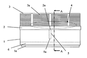
- FIG. 1 shows a schematic elevational side view of a first embodiment of the device of the present invention
- FIG. 2 shows a schematic elevational front view of the device represented in FIG. 1 ;
- FIG. 3 shows a schematic elevational side view of the lid of the device represented in FIG. 1 ;
- FIG. 4 shows a schematic elevational side view of the support tray of the device represented in FIG. 1 ;
- FIG. 5 shows a schematic elevational side view of the receptacle of the device represented in FIG. 1 ;
- FIG. 6 shows a schematic elevational front view of the lid of the device represented in FIG. 1 ;
- FIG. 7 shows a schematic elevational front view of the support tray of the device represented in FIG. 1 ;
- FIG. 8 shows a schematic elevational front view of the receptacle of the device represented in FIG. 1 ;
- FIG. 9 shows a schematic upper plan view of an embodiment of the receptacle of the device represented in FIG. 1 ;
- FIG. 10 shows a schematic lower plan view of an embodiment of the receptacle of the device represented in FIG. 1 ;
- FIG. 11 shows a schematic upper plan view of an embodiment of the support tray of the device represented in FIG. 1 ;
- FIG. 12 shows a schematic lower plan view of an embodiment of the support tray of the device represented in FIG. 1 ;
- FIG. 13 shows a schematic upper plan view of an embodiment of the lid of the device represented in FIG. 1 ;
- FIG. 14 shows a schematic sectional side view along plane A-A of the device shown in FIG. 1 ;
- FIG. 15 corresponds to schematic sectional side views along planes C-C, C′-C′ of the receptacle shown in FIG. 9 , G-G, G′-G′ of the support tray shown in FIG. 12 , and I-I, I′-I′ of the lid shown in FIG. 13 ;
- FIG. 16 shows a schematic sectional side view along plane B-B of the device shown in FIG. 2 ;
- FIG. 17 corresponds to schematic sectional side views along planes D-D, D′-D′ of the receptacle shown in FIG. 10 , F-F, F′-F′ of the support tray shown in FIG. 12 , and H-H, H′-H′ of the lid shown in FIG. 15 ;
- FIG. 18 shows a schematic sectional side view of an embodiment of the drainage tube of the device represented in FIG. 1 ;
- FIG. 19 shows a schematic lower plan view of the drainage tube shown in FIG. 18 ;
- FIG. 20 shows a schematic sectional side view of the support tray and drainage tube, along plane E-E, shown in FIG. 12 ;
- FIG. 21 shows a schematic sectional elevational side view of an embodiment of a sealing plug for the support tray evacuation orifice
- FIG. 22 shows a schematic upper plan view of the sealing plug shown in FIG. 21 ;
- FIG. 23 shows a schematic lower plan view of the sealing plug shown in FIG. 21 ;
- FIG. 24 shows a schematic sectional view along plane J-J of the sealing plug shown in FIG. 22 ;
- FIG. 25 shows a schematic sectional view along plane K-K of the sealing plug shown in FIG. 22 ;
- FIG. 26 shows an elevational side view of the device shown in the figure but with its elements disposed in storage position
- FIG. 27 shows a cross-sectional view along a side of the device represented in FIG. 26 ;
- FIG. 28 shows a cross-sectional view along a wall of the device represented in FIG. 26 ;
- FIG. 29 shows a schematic elevational side view of the second embodiment of the device of the present invention.
- FIG. 30 shows a schematic elevational side view of the lid of the device represented in FIG. 29 ;
- FIG. 31 shows a schematic elevational side view of the support tray of the device represented in FIG. 29 ;
- FIG. 32 shows a schematic upper plan view of an embodiment of the support tray of the device represented in FIG. 29 ;
- FIG. 33 shows a schematic lower plan view of an embodiment of the support tray of the device represented in FIG. 29 ;
- FIG. 34 corresponds to schematic sectional views respectively along planes D-D, D′-D′ of the receptacle shown in FIG. 10 , M-M, M′-M′ of the support tray shown in FIG. 32 , and N-N, N′-N′ of the lid shown in FIG. 33 ;
- FIG. 35 shows a schematic sectional side view along plane L-L of the device represented in FIG. 29 .
- FIGS. 1 to 28 In a first embodiment of the container device for en environmental humidity absorber with an anti-spill system of the present invention, represented in FIGS. 1 to 28 , we can observe that it comprises a lower receptacle ( 1 ) to collect saline liquid ( 6 ), a support tray ( 2 ) for hygroscopic material ( 4 ) contained in a permeable receptacle, and an upper lid ( 3 ) with ventilation holes ( 3 a ), disposed over the tray ( 2 ).
- a drainage tube ( 5 ) that extends vertically towards the bottom ( 1 b ) of the receptacle ( 1 ) emerges from the drainage hole ( 2 a ).
- the receptacle ( 1 ) has a bottom ( 1 b ), a wall ( 1 c ) and an upper edge ( 1 a ) that defines an upper opening. Similarly, it comprises a recessed rib ( 1 d ) that emerges peripherally from an inner upper side of its wall ( 1 c ) and fits into a peripheral inlet ( 2 p ) in an outer part of the wall ( 2 l ) of the tray ( 2 ).
- the receptacle ( 1 ) is also comprised of a support flap ( 1 e ) that extends vertically downwards from its bottom ( 1 b ).
- the lid ( 3 ) comprises a closed upper base ( 3 f ), a peripheral flap ( 3 d ) that projects laterally from the lid ( 3 ) and rests on the wall ( 2 l ) of the tray, and a lower peripheral flange ( 3 e ) in contact with a lower part of the wall ( 2 l ) of the tray ( 2 ).
- the tray ( 2 ) is sealed to the upper edge ( 1 a ) of the receptacle ( 1 ), and has a base ( 2 r ), an upper surface ( 2 d ) tilted towards and around a central drainage hole ( 2 a ), and a wall ( 2 l ) that peripherally defines the upper surface ( 2 d ) of the tray ( 2 ), and an upper surface ( 2 k ).
- Two vertical recessed projections ( 2 b ) which are embedded into the complementary openings ( 3 c ) of respective horizontal recessed tongues ( 3 b ) that emerge from either side of the lid ( 3 ), emerge from two opposed segments of the wall ( 2 l ) corresponding to the walls of the tray ( 2 ).
- the tray ( 2 ) also comprises an outer flap ( 2 j ) that extends vertically downwards, and a horizontal support segment ( 2 q ) that extends towards the exterior of the tray ( 2 ) and joins the outer flap ( 2 j ) to the wall ( 2 l ) of the tray ( 2 ), in such a way that a gap ( 2 o ) in which the upper part of the wall ( 1 c ) of the receptacle ( 1 ) is embedded, is defined between the outer flap ( 2 j ), the support segment ( 2 q ) and the wall ( 2 l ) of the tray ( 2 ).
- the outer flap ( 2 j ) of the tray ( 2 ) has an upper vertical extension that surrounds at least one lower side of the lid ( 3 ). From each of the wall ( 2 l ) segments from which the recessed projections ( 2 b ) emerge, the upper vertical extension of the outer flap ( 2 l ) of the tray comprises an opening ( 2 g ) for the recessed projection ( 2 b ) that forms an access to the horizontal recessed tongue ( 3 b ) of the lid ( 3 ).
- the upper surface ( 2 d ) of the tray ( 2 ) has centering projections ( 2 h ) to maintain the receptacle that contains the hygroscopic material ( 4 ) in a stable, centered position.
- a lower flap also emerges vertically from the lower surface ( 2 k ) of the tray ( 2 ).
- the support tray ( 2 ) also comprises an evacuation orifice ( 2 c ) for the liquid ( 6 ), which can sealed with a removable plug ( 7 ) disposed close to the two adjacent parts of the wall ( 2 l ) of the support tray ( 2 ).
- Said plug ( 7 ) is comprised of an upper part ( 7 a ) resembling a flat vertical grip flap and a lower part ( 7 b ) that fits into the evacuation orifice ( 2 c ) that crosses the base ( 2 r ) of the support tray.
- a ring flange ( 7 e ) that extends further than the evacuation orifice ( 2 c ) emerges between the upper part ( 7 a ) and lower part ( 7 b ) of the plug ( 7 ).
- Vertical insertion ribs ( 7 d ) are disposed along the radial surface of the lower part ( 7 b ), while the lower extreme part ( 7 e ) has an inverse truncated-cone section that facilitates insertion of the plug ( 7 ) in the evacuation orifice.
- the drainage tube ( 5 ) is comprised of an upper inlet ( 5 b ), a downward part ( 5 c ) inside of which an inner channel ( 5 ) with a slightly inverted truncated cone-shaped longitudinal section extends, and a lower outlet ( 5 a ) with a free edge substantially parallel and separated from the bottom of the receptacle ( 1 b ) and is removably embedded in the base ( 2 r ) of the tray ( 2 ).
- the drainage tube ( 5 ) inlet ( 5 b ) is surrounded by a ring widening ( 5 d ) that fits into a complementary ring slot ( 2 n ) that surrounds the drainage hole ( 2 a ).
- FIGS. 26 to 28 represent the device of the present invention in a storage position in which it should, logically, occupy the least possible space.
- the lid ( 3 ) is turned 180° and disposed over the interior of the receptacle ( 1 ), in such a way that the peripheral flap ( 3 d ) and the recessed tongue ( 3 b ) rest on the upper edge ( 1 a ) of the receptacle ( 1 ).
- the tray ( 2 ) is also turned 180° and disposed in such a way that its inner wall ( 2 l ) is in contact with the outer part of the peripheral vertical inner flange ( 3 e ), while its support segment ( 2 q ) rests on the peripheral flap ( 3 d ) and the recessed tongue ( 3 b ) of the lid ( 3 ).
- the recessed projection ( 2 b ) of the tray ( 2 ) is embedded into the opening ( 3 c ) of the recessed tongue ( 3 b ).
- the inner flap ( 2 i ) of the tray ( 2 ) is turned upwards in such a way that it provides a support means to pile another device with identical characteristics to those previously described, the support flap ( 1 e ′) of which surrounds the inner flap ( 2 i ) of the tray and the bottom ( 1 b ′) of which rests on the free edge of said support flap ( 1 e ) or, in another embodiment, on the lower upward-turned edge ( 2 k ) of the tray ( 2 ).
- the tube ( 5 ) has been disassembled and is inserted into the lid ( 3 ).
- the second embodiment of the device of the present invention represented in FIGS. 29 to 35 is differentiated from the first embodiment fundamentally in that two lateral vertical recessed projections ( 2 b ) emerge from two lateral segments opposite the wall ( 2 l ) of the tray ( 2 ), which are embedded into the complementary openings ( 3 c ) of respective lateral horizontal recessed tongues ( 3 b ′) that emerge from either side of the lid ( 3 ).
- the upper vertical extension of the outer flap ( 2 l ) of the tray comprise an opening ( 2 g ′) for the lateral recessed projection ( 2 b ′) that forms an access to the lateral horizontal recessed tongue ( 3 b ′) of the lid ( 3 ).
- the ultimate purpose of the two additional lateral recessed units formed by the lateral recessed projections ( 2 b ′) and the lateral recessed tongues ( 3 b ′) with their respective openings ( 3 c ′), respectively, is to reinforce the join between the lid ( 3 ) and the tray ( 2 ), which is particularly useful when the container device has extending sides.
Landscapes
- Engineering & Computer Science (AREA)
- Chemical & Material Sciences (AREA)
- Combustion & Propulsion (AREA)
- Mechanical Engineering (AREA)
- General Engineering & Computer Science (AREA)
- Analytical Chemistry (AREA)
- General Chemical & Material Sciences (AREA)
- Oil, Petroleum & Natural Gas (AREA)
- Chemical Kinetics & Catalysis (AREA)
- Closures For Containers (AREA)
- Packages (AREA)
Applications Claiming Priority (3)
| Application Number | Priority Date | Filing Date | Title |
|---|---|---|---|
| EP07381064.0 | 2007-09-18 | ||
| EP07381064 | 2007-09-18 | ||
| EP07381064A EP2039416B1 (de) | 2007-09-18 | 2007-09-18 | Behälter für ein Feuchtigkeitsabsorptionsmaterial mit Auslaufschutzvorrichtung |
Related Parent Applications (1)
| Application Number | Title | Priority Date | Filing Date |
|---|---|---|---|
| US12/106,217 Continuation US7893763B2 (en) | 2007-04-18 | 2008-04-18 | Apparatus and method for power added efficiency optimization of high amplification applications |
Related Child Applications (1)
| Application Number | Title | Priority Date | Filing Date |
|---|---|---|---|
| US13/020,983 Continuation US20110121894A1 (en) | 2007-04-18 | 2011-02-04 | Apparatus and method for power added efficiency optimization of high amplification applications |
Publications (2)
| Publication Number | Publication Date |
|---|---|
| US20090071027A1 US20090071027A1 (en) | 2009-03-19 |
| US7748562B2 true US7748562B2 (en) | 2010-07-06 |
Family
ID=39145040
Family Applications (1)
| Application Number | Title | Priority Date | Filing Date |
|---|---|---|---|
| US12/106,271 Active 2029-01-23 US7748562B2 (en) | 2007-09-18 | 2008-04-19 | Container device for an environmental humidity absorber with an anti-spill system |
Country Status (5)
| Country | Link |
|---|---|
| US (1) | US7748562B2 (de) |
| EP (1) | EP2039416B1 (de) |
| AT (1) | ATE535299T1 (de) |
| ES (1) | ES2378483T3 (de) |
| PT (1) | PT2039416E (de) |
Families Citing this family (5)
| Publication number | Priority date | Publication date | Assignee | Title |
|---|---|---|---|---|
| TR200904692A2 (tr) * | 2009-06-16 | 2010-08-23 | Di̇nç Şaban | Yere sabitlenebilen nem yok edici muhafazası. |
| ES2345178B1 (es) * | 2010-04-23 | 2011-05-31 | Stimulo Design, S.L | Dispositivo deshumidificador portatil, y carga de producto higroscopocio para dicho dispositivo. |
| DE102015110678B4 (de) | 2015-07-02 | 2017-12-28 | ThoMar OHG | Faltbare Abtropfvorrichtung zum Aufnehmen und Halten eines Absorptionselementes sowie Luftentfeuchtungseinrichtung mit einem solchen Absorptionselement |
| US20190366265A1 (en) * | 2018-06-01 | 2019-12-05 | W.M. Barr & Company, Inc. | Spill resistant and moisture absorbing device |
| WO2022154215A1 (ko) * | 2021-01-14 | 2022-07-21 | 주식회사 엘지생활건강 | 제습제 용기 |
Citations (12)
| Publication number | Priority date | Publication date | Assignee | Title |
|---|---|---|---|---|
| FR2414948A1 (fr) | 1978-01-20 | 1979-08-17 | Darley Maurice | Appareil pour la dessication de l'air |
| FR2627401A1 (fr) | 1988-02-19 | 1989-08-25 | Velfor Plast | Absorbeur d'humidite perfectionne |
| FR2627400A2 (fr) | 1985-03-11 | 1989-08-25 | Vasseur Jean | Dispositif permettant d'absorber l'humidite a l'interieur d'un contenant en mouvement en evitant projection ou renversement du liquide obtenu |
| US5215561A (en) | 1992-02-25 | 1993-06-01 | Jerry Cameron | Moisture collection apparatus |
| WO1999010082A1 (de) | 1997-08-27 | 1999-03-04 | Henkel Kgaa | Absorptionseinrichtung und entsprechendes aufnahmeteil |
| US5931082A (en) * | 1969-04-09 | 1999-08-03 | Daewoong Electric Industrial Co., Ltd. | Double boiler for domestic use |
| EP1190760A2 (de) | 2000-09-13 | 2002-03-27 | Pocket srl | Feuchtigkeitabsorber mit Vorrichtung zur Verhinderung des Ausgiessens von kondensierter Flüssigkeit |
| US6463844B1 (en) * | 2000-08-04 | 2002-10-15 | Testrite Baparoma International, Llc | Baking pan |
| US6840396B2 (en) * | 2002-07-23 | 2005-01-11 | Penny M. Wuestman | Container assembly for maintaining container contents in a desired ambient temperature |
| FR2857275A1 (fr) | 2003-07-07 | 2005-01-14 | Henkel France | Dispositif d'absorption d'humidite |
| US6931755B1 (en) | 2004-10-04 | 2005-08-23 | Tsang-Hung Hsu | Dehumidifier as effected by moisture exchange |
| EP1619450A1 (de) | 2004-07-24 | 2006-01-25 | Henkel Kommanditgesellschaft auf Aktien | Luftentfeuchter |
Family Cites Families (10)
| Publication number | Priority date | Publication date | Assignee | Title |
|---|---|---|---|---|
| DE533061C (de) | 1925-08-11 | 1931-09-12 | Ernst Haas Dr | Verfahren und Vorrichtung zum Trocknen und/oder Desinfizieren geschlossener Raeume |
| ES237599Y (es) | 1978-08-01 | 1979-02-16 | Dispositivo deshumectador perfeccionado. | |
| ES281827Y (es) | 1983-03-31 | 1986-07-16 | Peiro Herrera Montserra | Deshumificador de gases perfeccionado. |
| ES280232Y (es) | 1984-06-27 | 1985-07-16 | Sistemas De Seguridad Catalanes, S.A. | Envolvente desmontable para substancias higroscopicas |
| FR2578444B1 (fr) | 1985-03-11 | 1989-11-17 | Vasseur Jean | Dispositif permettant d'absorber l'humidite a l'interieur d'un contenant en mouvement en evitant projection ou renversement du liquide obtenu |
| ES1003028Y (es) | 1987-07-30 | 1989-02-01 | Bolaseca, S.A. | Envolvente desmontable para sustancias higroscopicas |
| ES1012272Y (es) | 1989-12-01 | 1991-01-16 | Bolaseca, S.A. | Aparato para la eliminacion de la humedad del aire. |
| FR2658736B1 (fr) | 1990-02-28 | 1992-12-04 | Vasseur Jean | Dispositif permettant d'absorber la totalite de la solution obtenue par un absorbeur d'humidite. |
| ES1038304Y (es) | 1997-09-25 | 1999-05-01 | Serna Santos Manuel | Recipiente contenedor para sales antihumedad. |
| ES1038452Y (es) | 1997-10-16 | 1999-01-01 | Bolaseca Sa | Secador a base de substancias higroscopicas. |
-
2007
- 2007-09-18 AT AT07381064T patent/ATE535299T1/de active
- 2007-09-18 ES ES07381064T patent/ES2378483T3/es active Active
- 2007-09-18 EP EP07381064A patent/EP2039416B1/de active Active
- 2007-09-18 PT PT07381064T patent/PT2039416E/pt unknown
-
2008
- 2008-04-19 US US12/106,271 patent/US7748562B2/en active Active
Patent Citations (12)
| Publication number | Priority date | Publication date | Assignee | Title |
|---|---|---|---|---|
| US5931082A (en) * | 1969-04-09 | 1999-08-03 | Daewoong Electric Industrial Co., Ltd. | Double boiler for domestic use |
| FR2414948A1 (fr) | 1978-01-20 | 1979-08-17 | Darley Maurice | Appareil pour la dessication de l'air |
| FR2627400A2 (fr) | 1985-03-11 | 1989-08-25 | Vasseur Jean | Dispositif permettant d'absorber l'humidite a l'interieur d'un contenant en mouvement en evitant projection ou renversement du liquide obtenu |
| FR2627401A1 (fr) | 1988-02-19 | 1989-08-25 | Velfor Plast | Absorbeur d'humidite perfectionne |
| US5215561A (en) | 1992-02-25 | 1993-06-01 | Jerry Cameron | Moisture collection apparatus |
| WO1999010082A1 (de) | 1997-08-27 | 1999-03-04 | Henkel Kgaa | Absorptionseinrichtung und entsprechendes aufnahmeteil |
| US6463844B1 (en) * | 2000-08-04 | 2002-10-15 | Testrite Baparoma International, Llc | Baking pan |
| EP1190760A2 (de) | 2000-09-13 | 2002-03-27 | Pocket srl | Feuchtigkeitabsorber mit Vorrichtung zur Verhinderung des Ausgiessens von kondensierter Flüssigkeit |
| US6840396B2 (en) * | 2002-07-23 | 2005-01-11 | Penny M. Wuestman | Container assembly for maintaining container contents in a desired ambient temperature |
| FR2857275A1 (fr) | 2003-07-07 | 2005-01-14 | Henkel France | Dispositif d'absorption d'humidite |
| EP1619450A1 (de) | 2004-07-24 | 2006-01-25 | Henkel Kommanditgesellschaft auf Aktien | Luftentfeuchter |
| US6931755B1 (en) | 2004-10-04 | 2005-08-23 | Tsang-Hung Hsu | Dehumidifier as effected by moisture exchange |
Non-Patent Citations (1)
| Title |
|---|
| Mar. 12, 2008, EP Search Report EP 07381064. |
Also Published As
| Publication number | Publication date |
|---|---|
| US20090071027A1 (en) | 2009-03-19 |
| EP2039416A1 (de) | 2009-03-25 |
| EP2039416B1 (de) | 2011-11-30 |
| ES2378483T3 (es) | 2012-04-13 |
| ATE535299T1 (de) | 2011-12-15 |
| PT2039416E (pt) | 2012-03-16 |
Similar Documents
| Publication | Publication Date | Title |
|---|---|---|
| US7748562B2 (en) | Container device for an environmental humidity absorber with an anti-spill system | |
| US7032831B2 (en) | Container for a device for dispensing a volatile liquid | |
| US6134833A (en) | Self-watering plant container | |
| ES2463475T3 (es) | Recipiente resistente a los derrames | |
| US20090302128A1 (en) | Adjustable volatile substance diffuser device with a container with a membrane | |
| DK2594857T3 (en) | Luftentfeuchter | |
| KR200438782Y1 (ko) | 용기캡의 제습구조 | |
| KR101777235B1 (ko) | 누수 방지 가습장치 | |
| KR20160003171U (ko) | 배수가 용이한 화분 받침대 | |
| US8157106B2 (en) | Garbage container with protected drain | |
| ES2345178B1 (es) | Dispositivo deshumidificador portatil, y carga de producto higroscopocio para dicho dispositivo. | |
| KR200490711Y1 (ko) | 제습제 보관 용기 | |
| EP1779043B1 (de) | Luftentfeuchter | |
| US20190366265A1 (en) | Spill resistant and moisture absorbing device | |
| JP5431854B2 (ja) | 除湿器用受け皿 | |
| CN208193043U (zh) | 便携式洗浴用品收纳装置 | |
| KR101877555B1 (ko) | 쏟아짐 방지 배출장치 | |
| JPH10225242A (ja) | 植木鉢 | |
| JPS582417Y2 (ja) | 除湿容器 | |
| JPS6240668Y2 (de) | ||
| JP3889170B2 (ja) | 化粧料容器 | |
| JP6700879B2 (ja) | 脱臭具 | |
| KR20230062028A (ko) | 다회용 습기제거제 | |
| JPH10180029A (ja) | 除湿器用容器 | |
| KR20170002651U (ko) | 제습제 케이스 |
Legal Events
| Date | Code | Title | Description |
|---|---|---|---|
| AS | Assignment |
Owner name: TOP GRADE, S.L., SPAIN Free format text: ASSIGNMENT OF ASSIGNORS INTEREST;ASSIGNOR:SCHMIDT DIOS, EVA;REEL/FRAME:020901/0098 Effective date: 20080417 |
|
| STCF | Information on status: patent grant |
Free format text: PATENTED CASE |
|
| FPAY | Fee payment |
Year of fee payment: 4 |
|
| MAFP | Maintenance fee payment |
Free format text: PAYMENT OF MAINTENANCE FEE, 8TH YR, SMALL ENTITY (ORIGINAL EVENT CODE: M2552) Year of fee payment: 8 |
|
| MAFP | Maintenance fee payment |
Free format text: PAYMENT OF MAINTENANCE FEE, 12TH YR, SMALL ENTITY (ORIGINAL EVENT CODE: M2553); ENTITY STATUS OF PATENT OWNER: SMALL ENTITY Year of fee payment: 12 |