US7768709B2 - Long time aperture optical tapped delay line - Google Patents
Long time aperture optical tapped delay line Download PDFInfo
- Publication number
- US7768709B2 US7768709B2 US11/346,566 US34656606A US7768709B2 US 7768709 B2 US7768709 B2 US 7768709B2 US 34656606 A US34656606 A US 34656606A US 7768709 B2 US7768709 B2 US 7768709B2
- Authority
- US
- United States
- Prior art keywords
- beam divergence
- input
- optical
- diameter
- output
- Prior art date
- Legal status (The legal status is an assumption and is not a legal conclusion. Google has not performed a legal analysis and makes no representation as to the accuracy of the status listed.)
- Expired - Fee Related, expires
Links
- 230000003287 optical effect Effects 0.000 title claims abstract description 176
- 230000003595 spectral effect Effects 0.000 claims abstract description 56
- 238000000034 method Methods 0.000 claims abstract description 34
- 238000003384 imaging method Methods 0.000 claims description 30
- 210000001624 hip Anatomy 0.000 claims description 14
- 230000011514 reflex Effects 0.000 claims 1
- 238000001228 spectrum Methods 0.000 abstract description 38
- 238000012545 processing Methods 0.000 abstract description 27
- 239000000835 fiber Substances 0.000 description 27
- 238000010183 spectrum analysis Methods 0.000 description 27
- 239000011248 coating agent Substances 0.000 description 16
- 238000000576 coating method Methods 0.000 description 16
- 238000013461 design Methods 0.000 description 15
- 239000013307 optical fiber Substances 0.000 description 13
- 238000000926 separation method Methods 0.000 description 12
- 238000004891 communication Methods 0.000 description 11
- 230000004044 response Effects 0.000 description 11
- 230000008859 change Effects 0.000 description 10
- 238000002310 reflectometry Methods 0.000 description 10
- 239000006185 dispersion Substances 0.000 description 8
- 238000001914 filtration Methods 0.000 description 8
- 230000010363 phase shift Effects 0.000 description 8
- 230000008901 benefit Effects 0.000 description 7
- 230000008569 process Effects 0.000 description 7
- 241001270131 Agaricus moelleri Species 0.000 description 5
- 238000004458 analytical method Methods 0.000 description 5
- 230000000694 effects Effects 0.000 description 5
- 230000002441 reversible effect Effects 0.000 description 5
- 230000003111 delayed effect Effects 0.000 description 4
- 230000009467 reduction Effects 0.000 description 4
- 238000005070 sampling Methods 0.000 description 4
- 230000008878 coupling Effects 0.000 description 3
- 238000010168 coupling process Methods 0.000 description 3
- 238000005859 coupling reaction Methods 0.000 description 3
- 230000001419 dependent effect Effects 0.000 description 3
- 238000010586 diagram Methods 0.000 description 3
- 238000009826 distribution Methods 0.000 description 3
- 230000010076 replication Effects 0.000 description 3
- 230000007480 spreading Effects 0.000 description 3
- 238000003892 spreading Methods 0.000 description 3
- 239000000758 substrate Substances 0.000 description 3
- 239000010409 thin film Substances 0.000 description 3
- 230000005540 biological transmission Effects 0.000 description 2
- 239000000969 carrier Substances 0.000 description 2
- 239000012141 concentrate Substances 0.000 description 2
- 239000000470 constituent Substances 0.000 description 2
- 230000003247 decreasing effect Effects 0.000 description 2
- 238000001514 detection method Methods 0.000 description 2
- 238000004519 manufacturing process Methods 0.000 description 2
- 239000000463 material Substances 0.000 description 2
- 238000012634 optical imaging Methods 0.000 description 2
- 230000001902 propagating effect Effects 0.000 description 2
- 230000006798 recombination Effects 0.000 description 2
- 238000005215 recombination Methods 0.000 description 2
- 230000002829 reductive effect Effects 0.000 description 2
- 230000002123 temporal effect Effects 0.000 description 2
- 239000000853 adhesive Substances 0.000 description 1
- 230000001070 adhesive effect Effects 0.000 description 1
- 230000003466 anti-cipated effect Effects 0.000 description 1
- 238000013459 approach Methods 0.000 description 1
- 238000003491 array Methods 0.000 description 1
- 230000015572 biosynthetic process Effects 0.000 description 1
- 230000015556 catabolic process Effects 0.000 description 1
- 239000002131 composite material Substances 0.000 description 1
- 238000006731 degradation reaction Methods 0.000 description 1
- 230000001934 delay Effects 0.000 description 1
- 238000005516 engineering process Methods 0.000 description 1
- 238000002474 experimental method Methods 0.000 description 1
- 238000009501 film coating Methods 0.000 description 1
- 229920005560 fluorosilicone rubber Polymers 0.000 description 1
- 230000036039 immunity Effects 0.000 description 1
- 238000002372 labelling Methods 0.000 description 1
- 230000000670 limiting effect Effects 0.000 description 1
- 239000004973 liquid crystal related substance Substances 0.000 description 1
- 230000007246 mechanism Effects 0.000 description 1
- 239000004065 semiconductor Substances 0.000 description 1
- 230000003068 static effect Effects 0.000 description 1
- 238000003860 storage Methods 0.000 description 1
- 238000003786 synthesis reaction Methods 0.000 description 1
- 230000002194 synthesizing effect Effects 0.000 description 1
- 238000012360 testing method Methods 0.000 description 1
Images




Classifications
-
- G—PHYSICS
- G01—MEASURING; TESTING
- G01J—MEASUREMENT OF INTENSITY, VELOCITY, SPECTRAL CONTENT, POLARISATION, PHASE OR PULSE CHARACTERISTICS OF INFRARED, VISIBLE OR ULTRAVIOLET LIGHT; COLORIMETRY; RADIATION PYROMETRY
- G01J3/00—Spectrometry; Spectrophotometry; Monochromators; Measuring colours
- G01J3/12—Generating the spectrum; Monochromators
- G01J3/26—Generating the spectrum; Monochromators using multiple reflection, e.g. Fabry-Perot interferometer, variable interference filters
-
- G—PHYSICS
- G01—MEASURING; TESTING
- G01J—MEASUREMENT OF INTENSITY, VELOCITY, SPECTRAL CONTENT, POLARISATION, PHASE OR PULSE CHARACTERISTICS OF INFRARED, VISIBLE OR ULTRAVIOLET LIGHT; COLORIMETRY; RADIATION PYROMETRY
- G01J3/00—Spectrometry; Spectrophotometry; Monochromators; Measuring colours
- G01J3/02—Details
-
- G—PHYSICS
- G01—MEASURING; TESTING
- G01J—MEASUREMENT OF INTENSITY, VELOCITY, SPECTRAL CONTENT, POLARISATION, PHASE OR PULSE CHARACTERISTICS OF INFRARED, VISIBLE OR ULTRAVIOLET LIGHT; COLORIMETRY; RADIATION PYROMETRY
- G01J3/00—Spectrometry; Spectrophotometry; Monochromators; Measuring colours
- G01J3/02—Details
- G01J3/0205—Optical elements not provided otherwise, e.g. optical manifolds, diffusers, windows
-
- G—PHYSICS
- G01—MEASURING; TESTING
- G01J—MEASUREMENT OF INTENSITY, VELOCITY, SPECTRAL CONTENT, POLARISATION, PHASE OR PULSE CHARACTERISTICS OF INFRARED, VISIBLE OR ULTRAVIOLET LIGHT; COLORIMETRY; RADIATION PYROMETRY
- G01J3/00—Spectrometry; Spectrophotometry; Monochromators; Measuring colours
- G01J3/02—Details
- G01J3/0205—Optical elements not provided otherwise, e.g. optical manifolds, diffusers, windows
- G01J3/0208—Optical elements not provided otherwise, e.g. optical manifolds, diffusers, windows using focussing or collimating elements, e.g. lenses or mirrors; performing aberration correction
-
- G—PHYSICS
- G01—MEASURING; TESTING
- G01J—MEASUREMENT OF INTENSITY, VELOCITY, SPECTRAL CONTENT, POLARISATION, PHASE OR PULSE CHARACTERISTICS OF INFRARED, VISIBLE OR ULTRAVIOLET LIGHT; COLORIMETRY; RADIATION PYROMETRY
- G01J3/00—Spectrometry; Spectrophotometry; Monochromators; Measuring colours
- G01J3/02—Details
- G01J3/0205—Optical elements not provided otherwise, e.g. optical manifolds, diffusers, windows
- G01J3/0218—Optical elements not provided otherwise, e.g. optical manifolds, diffusers, windows using optical fibers
-
- G—PHYSICS
- G02—OPTICS
- G02B—OPTICAL ELEMENTS, SYSTEMS OR APPARATUS
- G02B27/00—Optical systems or apparatus not provided for by any of the groups G02B1/00 - G02B26/00, G02B30/00
- G02B27/10—Beam splitting or combining systems
- G02B27/106—Beam splitting or combining systems for splitting or combining a plurality of identical beams or images, e.g. image replication
-
- G—PHYSICS
- G02—OPTICS
- G02B—OPTICAL ELEMENTS, SYSTEMS OR APPARATUS
- G02B27/00—Optical systems or apparatus not provided for by any of the groups G02B1/00 - G02B26/00, G02B30/00
- G02B27/10—Beam splitting or combining systems
- G02B27/1066—Beam splitting or combining systems for enhancing image performance, like resolution, pixel numbers, dual magnifications or dynamic range, by tiling, slicing or overlapping fields of view
-
- G—PHYSICS
- G02—OPTICS
- G02B—OPTICAL ELEMENTS, SYSTEMS OR APPARATUS
- G02B27/00—Optical systems or apparatus not provided for by any of the groups G02B1/00 - G02B26/00, G02B30/00
- G02B27/10—Beam splitting or combining systems
- G02B27/12—Beam splitting or combining systems operating by refraction only
- G02B27/123—The splitting element being a lens or a system of lenses, including arrays and surfaces with refractive power
-
- G—PHYSICS
- G02—OPTICS
- G02B—OPTICAL ELEMENTS, SYSTEMS OR APPARATUS
- G02B27/00—Optical systems or apparatus not provided for by any of the groups G02B1/00 - G02B26/00, G02B30/00
- G02B27/10—Beam splitting or combining systems
- G02B27/14—Beam splitting or combining systems operating by reflection only
- G02B27/143—Beam splitting or combining systems operating by reflection only using macroscopically faceted or segmented reflective surfaces
-
- G—PHYSICS
- G02—OPTICS
- G02B—OPTICAL ELEMENTS, SYSTEMS OR APPARATUS
- G02B27/00—Optical systems or apparatus not provided for by any of the groups G02B1/00 - G02B26/00, G02B30/00
- G02B27/10—Beam splitting or combining systems
- G02B27/14—Beam splitting or combining systems operating by reflection only
- G02B27/144—Beam splitting or combining systems operating by reflection only using partially transparent surfaces without spectral selectivity
-
- G—PHYSICS
- G02—OPTICS
- G02B—OPTICAL ELEMENTS, SYSTEMS OR APPARATUS
- G02B6/00—Light guides; Structural details of arrangements comprising light guides and other optical elements, e.g. couplings
- G02B6/24—Coupling light guides
- G02B6/26—Optical coupling means
- G02B6/28—Optical coupling means having data bus means, i.e. plural waveguides interconnected and providing an inherently bidirectional system by mixing and splitting signals
- G02B6/293—Optical coupling means having data bus means, i.e. plural waveguides interconnected and providing an inherently bidirectional system by mixing and splitting signals with wavelength selective means
- G02B6/29346—Optical coupling means having data bus means, i.e. plural waveguides interconnected and providing an inherently bidirectional system by mixing and splitting signals with wavelength selective means operating by wave or beam interference
- G02B6/29358—Multiple beam interferometer external to a light guide, e.g. Fabry-Pérot, etalon, VIPA plate, OTDL plate, continuous interferometer, parallel plate resonator
-
- G—PHYSICS
- G02—OPTICS
- G02B—OPTICAL ELEMENTS, SYSTEMS OR APPARATUS
- G02B6/00—Light guides; Structural details of arrangements comprising light guides and other optical elements, e.g. couplings
- G02B6/24—Coupling light guides
- G02B6/26—Optical coupling means
- G02B6/28—Optical coupling means having data bus means, i.e. plural waveguides interconnected and providing an inherently bidirectional system by mixing and splitting signals
- G02B6/293—Optical coupling means having data bus means, i.e. plural waveguides interconnected and providing an inherently bidirectional system by mixing and splitting signals with wavelength selective means
- G02B6/29379—Optical coupling means having data bus means, i.e. plural waveguides interconnected and providing an inherently bidirectional system by mixing and splitting signals with wavelength selective means characterised by the function or use of the complete device
- G02B6/2938—Optical coupling means having data bus means, i.e. plural waveguides interconnected and providing an inherently bidirectional system by mixing and splitting signals with wavelength selective means characterised by the function or use of the complete device for multiplexing or demultiplexing, i.e. combining or separating wavelengths, e.g. 1xN, NxM
Definitions
- the present invention relates to optical signal processing. More specifically, the present invention relates to a method and apparatus for enabling high-resolution optical spectrum analysis or channelization, and for enabling related signal processing operations.
- optical communications and sensing has both fueled and benefited from new and better devices for placing signals on and detecting them from light (or optical carriers).
- the improved optical system performance along with inherent advantages of optical signals (e.g., size, low loss, bandwidth, immunity to electrical interference, etc.), has led to a natural progression in need for and advantage of processing optical signals.
- the types of signals to be processed can be digital or analog; may include various types of information such as audio, video, image, data, radar, and other signals; and may exist at various data rates, bandwidths, protocols, or optical modulation types.
- signal processing includes but is not limited to conventional filtering, multiplexing, coding, routing, analyzing, correlating, and synthesizing signals. With the gaining prevalence of signals in the optical form, new methods, techniques, and devices are needed to make these signal processing functions, which typically utilize electrical or other techniques, readily available for processing optical signals.
- Fabry-Perot interferometers have highest throughput when the input beam is well collimated and only a single (or narrow band of) wavelength is being selected or separated.
- the fall-off (or “skirts”) of the optical fringes formed by the Fabry-Perot interferometer is relatively large, which limits the crosstalk and channel separation of the device.
- FIG. 15 shows an example of a prior art planar waveguide integrated optical multiplexer and demultiplexer device, as disclosed by Bhagavatula in U.S. Pat. No. 6,111,674.
- a multiple-wavelength input signal is demultiplexed or channelized using a Fabry-Perot thin film stack consisting of alternating partially reflective and transmissive layers.
- the angularly dispersed wavelengths emerge from the “optical path length difference generator” and are individually coupled to a fan-shaped output array of waveguides by means of a focusing lens.
- This device could be fabricated as either a planar or a hybrid integrated optical (IO) structure.
- the optical bandwidth of the signal should be less than half the free spectral range; thus, the bandwidth of the optical signal should be less than about 10 GHz.
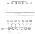
- the spectral resolution provided by the array equals the free spectral range divided by the number of taps or output fiber lines 76 into which the optical signal is efficiently coupled. Since the diffractive array 76 produces eight time-delayed outputs, the spectral resolution obtained is about 2.5 GHz. This resolution is much less than the resolution obtained by preferred embodiments of the present invention. Additionally, fabrication and stability of this device may be difficult as environmentally-independent, very precise fiber lengths are needed for proper operation.
- FIG. 9 illustrates an example of a schematic block diagram of the functional operation of a prior art device in a single-input arrangement.
- FIG. 12 illustrates an example of a design for a very large time-bandwidth product two-dimensional (2-D) folded spectrum analyzer.
- FIG. 13 illustrates a second example of a design for a large time-bandwidth product two-dimensional (2-D) folded spectrum analyzer or channelizer.
- the subassembly labeled “Narrowband Froehlich Cell” represents the OTDL in accordance with the present invention.
- FIGS. 12 and 13 illustrate examples of a general purpose 2-D arrangement that could be used for various applications, including but not limited to spectrum analysis, channelization, and dispersion compensation in a fiber-optic telecommunications system.
- FIG. 15 illustrates an example of a prior art planar waveguide integrated optical multiplexer and demultiplexer device.
- FIG. 22 illustrates an example of the present invention as a multiple input spectrum analyzer.
- a detector array or a fiber array may be placed at the focal plane.
- Three views of the same arrangement are shown for clarity: a) a 3-D view, b) top view, and c) side view.
- FIG. 5 illustrates an example of a preferred embodiment of an OTDL device in accordance with the present invention.
- the FIG. illustrates an optical cell or cavity ( 500 ) formed by a dihedral mirror pair at one end ( 503 A and 503 B), a lens ( 505 ), an output coupler mirror at the opposing end ( 511 ), and an input coupler element ( 513 ), which in this case is a prism.
- the distance from the vertex of the dihedral mirror pair to the lens is nominally equal to the lens focal length f ( 504 ), and the distance from the lens to the output coupler mirror also is nominally equal to f ( 507 )
- the total cell length L ( 506 ) is thus nominally equal to 2f.
- FIG. 8 illustrates an example of an alternate possible path for the chief ray of the light beam through the OTDL cell.
- the input beam ( 803 ) is inclined in the opposite sense to the x-axis as compared to FIG. 6 , which has the advantage of enabling the beamlet spacing ⁇ to be minimized.
- the change in inclination of the input beam causes a corresponding change in the inclination of the beams leaving and returning to the output coupler mirror.
- Beams leaving the output coupler mirror now are refracted by the lens toward the focal point F 1 ( 801 ) and are incident first on the upper dihedral mirror ( 503 A). After reflection from the lower dihedral mirror ( 503 B) the beams appear to be emanating from focal point F 2 .
- the second consequence is that as the output beamlets enlarge, the variation of the reflectivity of the cavity output surface across a single beamlet can no longer be ignored.
- the third consequence is that as the beamlets enlarge, they begin to overlap and the reflectivity at any given point on the cavity output surface acts on two or more beamlets and so power weighting control of the beamlets is no longer independent. That is, if the beam expands to the point where the output beamlets are overlapping or largely overlapping, then the weighting of individual beamlets can no longer be precisely controlled with the gradient reflectivity coating because each beamlet is covering (or sampling) its own reflectivity at its beam center and that of its neighbors.
- the present invention provides a way to overcome or obviate this beam expansion problem in applications in which one is attempting to achieve high spectral resolution and a long total path length is required through the device.
- the optimal application space is for FSRs of approximately 100 Gigahertz on the high frequency side (limited by large angles of the input beam to prevent beam overlap), and around 10 Gigahertz on the lower frequency side (limited by beam expansion degradations). It may become difficult to fabricate a known hyperfine device with an FSR much lower than about 10 Gigahertz.
- the planar reflective surfaces become large and may be difficult to fabricate with the required surface flatness.
- the upper limit on FSR for an OTDL device in accordance with the present invention is on the order of 5 to 10 Gigahertz (as limited by the thickness of the Imaging lens or spherical mirror curvature, as presented in FIG.
- the known hyperfine device and the OTDL device in accordance with the present invention span a wide range of application bandwidths. Both device types typically have roughly the same number of taps N, that is, the same number of resolution elements or resolution spots. Therefore, the known hyperfine device addresses applications requiring wider bandwidths and moderate spectral resolution, whereas the OTDL device in accordance with the present invention addresses applications requiring narrower bandwidths and very high spectral resolution.
- the dotted lines from the Fourier transform lens to the focal plane show roughly how the output Gaussian beamlets from the OTDL are focused to a spot at the focal plane.
- Light of wavelength ⁇ l creates wavefronts 1905 and is brought to a focus by the Fourier lens at one spot ( 1901 ), and light of wavelength ⁇ 2 creates wavefront 1906 and is brought to focus at a spatially separated spot ( 1902 ).
- the OTDL together with the Fourier transform optics spatially disperse the spectrum of the input light and each frequency component is distributed along the frequency axis marked “v.”
- the effect of imparting a phase shift to each sub-band is to introduce distortion. If the amount of distortion is sufficient, the information content becomes undecipherable and security is enhanced.
- the control computer 2606 instructs the modulator array how to modify the phase of the sub-bands in a manner that is unpredictable to anyone not having knowledge of the computer input.
- the rate at which the phase shifts are changed depends upon the level of security required.
- a fixed phase shift pattern will sufficiently distort the signal to make it incomprehensible; however, determined interceptors can analyze the signal and eventually determine, and reverse the effects of, the phase shift pattern.
- the fixed phase shift pattern can be changed occasionally, requiring the potential interceptor to start the analysis over again. For the highest security, this change must be made often enough to guarantee that even with the highest performance computational systems anticipated, the phase shifts do not remain static long enough for any known analysis to succeed before the pattern changes.
- the imaging camera assembly typically includes imaging optics to image the beamlets spots from the output coupler mirror to the camera sensor array.
- FIG. 17 b illustrates an image of the output beamlets from the output coupler mirror and is experimentally equivalent to viewing the output Gaussian beamlets ( 701 ) in FIG. 7 . It is important to note the substantially equal size of all the beamlets.
- a Fourier transform lens system maps the output beamlets of the output coupler mirror to a frequency plane.
- a line camera is placed at the focal plane to record the optical intensity along the frequency axis.
- this aperture that can be made relatively small in the present invention as compared to the known hyperfine device, for the same specifications.
- the reduction in aperture that one can achieve with the present invention versus a known hyperfine device is on the order of 10 ⁇ to 100 ⁇ .
- a key feature of the present invention is this reduction in aperture required at the output coupler mirror.
- the resulting router provides fixed channel routing (i.e., simple de-multiplexing) if the mirror segments are immovable.
- the router may be dynamically programmed to send channels to selected outputs.
- the input light is traced through system 1200 as follows.
- the input beam is introduced via an optical fiber 1207 .
- Imaging optics 1206 images the input free-space light beam 1205 through the input coupler prism to a 100 micron spot at the gradient reflectivity side (cavity side) of the output coupler mirror 1204 .
- the OTDL cavity as described with respect to FIGS. 5 through 8 , produces a plurality of M output beamlets from output coupler mirror 1204 , which are directed toward imaging optics 1208 .
- the plurality of M beamlets from 1201 is imaged as M input beams onto the input of the known hyperfine device 1209 .
- the known hyperfine device For each input beam, the known hyperfine device produces N beamlets for a total of M ⁇ N beamlets, which are directed toward Fourier transform optics (possibly anamorphic) 1210 .
- the set of M ⁇ N beamlets can be viewed as a plurality of quasi-continuous wavefronts (each with associated propagation directions), where there is one wavefront for each wavelength within the main input beam 1205 .
- the Fourier transform optics then transforms the wavefronts (with specific propagation directions) to spots on the focal plane 1213 .
- the spots on the focal plane have specific positions related to the associated wavefront directions and, therefore, to wavelength.
- input coupler could not include a prism at all.
- An example of an approach without using a prism would be an optical fiber with an attached or separate means of focusing the light positioned to the right of the output coupling mirror.
- the input beam from the fiber is directed into the cavity via an aperture near the position of aperture 1812 of the first example. The designer must take care to avoid obstructing the beamlet exiting the output coupler mirror with the fiber input assembly.
Landscapes
- Physics & Mathematics (AREA)
- General Physics & Mathematics (AREA)
- Spectroscopy & Molecular Physics (AREA)
- Optics & Photonics (AREA)
- Optical Communication System (AREA)
- Measurement Of The Respiration, Hearing Ability, Form, And Blood Characteristics Of Living Organisms (AREA)
- Light Guides In General And Applications Therefor (AREA)
- Mechanical Light Control Or Optical Switches (AREA)
- Optical Modulation, Optical Deflection, Nonlinear Optics, Optical Demodulation, Optical Logic Elements (AREA)
Priority Applications (1)
| Application Number | Priority Date | Filing Date | Title |
|---|---|---|---|
| US11/346,566 US7768709B2 (en) | 2005-02-03 | 2006-02-03 | Long time aperture optical tapped delay line |
Applications Claiming Priority (2)
| Application Number | Priority Date | Filing Date | Title |
|---|---|---|---|
| US64908705P | 2005-02-03 | 2005-02-03 | |
| US11/346,566 US7768709B2 (en) | 2005-02-03 | 2006-02-03 | Long time aperture optical tapped delay line |
Publications (2)
| Publication Number | Publication Date |
|---|---|
| US20070030567A1 US20070030567A1 (en) | 2007-02-08 |
| US7768709B2 true US7768709B2 (en) | 2010-08-03 |
Family
ID=36777940
Family Applications (1)
| Application Number | Title | Priority Date | Filing Date |
|---|---|---|---|
| US11/346,566 Expired - Fee Related US7768709B2 (en) | 2005-02-03 | 2006-02-03 | Long time aperture optical tapped delay line |
Country Status (5)
| Country | Link |
|---|---|
| US (1) | US7768709B2 (de) |
| EP (1) | EP1846801A4 (de) |
| JP (1) | JP2008530592A (de) |
| CA (1) | CA2596954A1 (de) |
| WO (1) | WO2006084086A2 (de) |
Cited By (3)
| Publication number | Priority date | Publication date | Assignee | Title |
|---|---|---|---|---|
| US20080219668A1 (en) * | 2007-03-08 | 2008-09-11 | Giovanni Barbarossa | Liquid crystal optical device with arrayed waveguide grating |
| US20090033788A1 (en) * | 2007-08-02 | 2009-02-05 | Micron Technology, Inc. | Integrated optical characteristic measurements in a cmos image sensor |
| US20150168554A1 (en) * | 2012-08-09 | 2015-06-18 | Israel Aerospace Industries Ltd. | Friend or foe identification system and method |
Families Citing this family (4)
| Publication number | Priority date | Publication date | Assignee | Title |
|---|---|---|---|---|
| US20110228939A1 (en) * | 2010-03-16 | 2011-09-22 | Telcordia Technologies, Inc. | System and methods for ocdm-based optical encryption using subsets of phase-locked frequency lines |
| FR3076356B1 (fr) * | 2017-12-29 | 2020-01-31 | Cailabs | Cavité monolithique pour la manipulation de la lumière |
| US10795170B2 (en) * | 2018-11-16 | 2020-10-06 | Ii-Vi Delaware Inc. | Multi-channel optical multiplexer or demultiplexer |
| CN110783801B (zh) * | 2019-10-31 | 2021-07-27 | 郑州轻工业学院 | 一种多波长脉冲延时输出的THz波参量源 |
Citations (17)
| Publication number | Priority date | Publication date | Assignee | Title |
|---|---|---|---|---|
| US5339186A (en) * | 1992-11-13 | 1994-08-16 | The University Of Colorado Foundation, Inc. | Optical data packet compressor/decompressor |
| US5852699A (en) | 1996-09-03 | 1998-12-22 | Lissotschenko; Vitaly | Fiber optical light transmission device for transmitting energy |
| US6111674A (en) | 1996-02-23 | 2000-08-29 | Corning Incorporated | Multiple reflection multiplexer and demultiplexer |
| US6266176B1 (en) | 1999-08-26 | 2001-07-24 | The Ohio State University | Device for optical interconnection |
| WO2001093465A1 (en) | 2000-05-31 | 2001-12-06 | Corning Incorporated | Tapped delay line diffractive array for sensing polarization mode dispersion |
| US6388815B1 (en) | 2000-08-24 | 2002-05-14 | The Ohio State University | Device and method for producing optically-controlled incremental time delays |
| US20020105705A1 (en) | 2001-01-22 | 2002-08-08 | Turpin Terry M. | Optical CDMA communications system using OTDC device |
| US20030128917A1 (en) | 2001-07-20 | 2003-07-10 | Turpin Terry M. | Method and apparatus for optical signal processing using an optical tapped delay line |
| US6608721B1 (en) | 2000-06-02 | 2003-08-19 | Essex Corporation | Optical tapped delay line |
| US6674939B1 (en) | 2002-03-26 | 2004-01-06 | The Ohio State University | Using fibers as delay elements in optical true-time delay devices based on the white cell |
| US6724951B1 (en) | 2002-03-26 | 2004-04-20 | The Ohio State University | Using fibers as shifting elements in optical interconnection devices based on the white cell |
| US6760140B1 (en) | 2002-03-01 | 2004-07-06 | The Ohio State University Research Foundation | Binary optical interconnection |
| US6766073B1 (en) | 2002-05-17 | 2004-07-20 | The Ohio State University | Optical circulator with large number of ports and no polarization-based components |
| US20040264695A1 (en) | 2002-11-19 | 2004-12-30 | Essex Corp. | Private and secure optical communication system using an optical tapped delay line |
| US20050114094A1 (en) | 2003-11-21 | 2005-05-26 | Lav Ivanovic | Reflectivity optimization for multilayer stacks |
| US7062174B2 (en) | 2001-01-22 | 2006-06-13 | Essex Corporation | Wavelength division multiplexing add-drop multiplexer using an optical tapped delay line |
| US7099531B2 (en) * | 2002-07-16 | 2006-08-29 | Chromatic Micro Optics, Inc. | Compensating for chromatic dispersion in optical fibers |
Family Cites Families (1)
| Publication number | Priority date | Publication date | Assignee | Title |
|---|---|---|---|---|
| FR2763767B1 (fr) * | 1997-05-26 | 1999-08-13 | France Telecom | Systeme de commutation optique spatiale a deflecteur acousto-optique multicanaux |
-
2006
- 2006-02-03 EP EP06720190A patent/EP1846801A4/de not_active Withdrawn
- 2006-02-03 CA CA002596954A patent/CA2596954A1/en not_active Abandoned
- 2006-02-03 JP JP2007554223A patent/JP2008530592A/ja active Pending
- 2006-02-03 WO PCT/US2006/003760 patent/WO2006084086A2/en not_active Ceased
- 2006-02-03 US US11/346,566 patent/US7768709B2/en not_active Expired - Fee Related
Patent Citations (18)
| Publication number | Priority date | Publication date | Assignee | Title |
|---|---|---|---|---|
| US5339186A (en) * | 1992-11-13 | 1994-08-16 | The University Of Colorado Foundation, Inc. | Optical data packet compressor/decompressor |
| US6111674A (en) | 1996-02-23 | 2000-08-29 | Corning Incorporated | Multiple reflection multiplexer and demultiplexer |
| US5852699A (en) | 1996-09-03 | 1998-12-22 | Lissotschenko; Vitaly | Fiber optical light transmission device for transmitting energy |
| US6266176B1 (en) | 1999-08-26 | 2001-07-24 | The Ohio State University | Device for optical interconnection |
| US6525889B1 (en) | 1999-08-26 | 2003-02-25 | The Ohio State University | Device and method for producing optically-controlled incremental time delays |
| WO2001093465A1 (en) | 2000-05-31 | 2001-12-06 | Corning Incorporated | Tapped delay line diffractive array for sensing polarization mode dispersion |
| US6608721B1 (en) | 2000-06-02 | 2003-08-19 | Essex Corporation | Optical tapped delay line |
| US6388815B1 (en) | 2000-08-24 | 2002-05-14 | The Ohio State University | Device and method for producing optically-controlled incremental time delays |
| US7062174B2 (en) | 2001-01-22 | 2006-06-13 | Essex Corporation | Wavelength division multiplexing add-drop multiplexer using an optical tapped delay line |
| US20020105705A1 (en) | 2001-01-22 | 2002-08-08 | Turpin Terry M. | Optical CDMA communications system using OTDC device |
| US20030128917A1 (en) | 2001-07-20 | 2003-07-10 | Turpin Terry M. | Method and apparatus for optical signal processing using an optical tapped delay line |
| US6760140B1 (en) | 2002-03-01 | 2004-07-06 | The Ohio State University Research Foundation | Binary optical interconnection |
| US6724951B1 (en) | 2002-03-26 | 2004-04-20 | The Ohio State University | Using fibers as shifting elements in optical interconnection devices based on the white cell |
| US6674939B1 (en) | 2002-03-26 | 2004-01-06 | The Ohio State University | Using fibers as delay elements in optical true-time delay devices based on the white cell |
| US6766073B1 (en) | 2002-05-17 | 2004-07-20 | The Ohio State University | Optical circulator with large number of ports and no polarization-based components |
| US7099531B2 (en) * | 2002-07-16 | 2006-08-29 | Chromatic Micro Optics, Inc. | Compensating for chromatic dispersion in optical fibers |
| US20040264695A1 (en) | 2002-11-19 | 2004-12-30 | Essex Corp. | Private and secure optical communication system using an optical tapped delay line |
| US20050114094A1 (en) | 2003-11-21 | 2005-05-26 | Lav Ivanovic | Reflectivity optimization for multilayer stacks |
Non-Patent Citations (3)
| Title |
|---|
| B. L. Anderson et al. (2002). "Optical True Time Delay for Phased-Array Antennas: Demonstration of a Quadratic White Cell," Applied Optics; vol. 41, No. 23, pp. 4912-4921. |
| International Search Report directed to PCT/US06/03760 mailed on Feb. 20, 2007; 1 page. |
| J. White (1942). "Long Optical Paths of Large Aperture," Journal of Optics Society of America, vol. 32, pp. 285-288. |
Cited By (5)
| Publication number | Priority date | Publication date | Assignee | Title |
|---|---|---|---|---|
| US20080219668A1 (en) * | 2007-03-08 | 2008-09-11 | Giovanni Barbarossa | Liquid crystal optical device with arrayed waveguide grating |
| US20090033788A1 (en) * | 2007-08-02 | 2009-02-05 | Micron Technology, Inc. | Integrated optical characteristic measurements in a cmos image sensor |
| US8085391B2 (en) * | 2007-08-02 | 2011-12-27 | Aptina Imaging Corporation | Integrated optical characteristic measurements in a CMOS image sensor |
| US20150168554A1 (en) * | 2012-08-09 | 2015-06-18 | Israel Aerospace Industries Ltd. | Friend or foe identification system and method |
| US9846235B2 (en) * | 2012-08-09 | 2017-12-19 | Israel Aerospace Industries Ltd. | Friend or foe identification system and method |
Also Published As
| Publication number | Publication date |
|---|---|
| EP1846801A2 (de) | 2007-10-24 |
| JP2008530592A (ja) | 2008-08-07 |
| WO2006084086A2 (en) | 2006-08-10 |
| WO2006084086A3 (en) | 2007-05-10 |
| US20070030567A1 (en) | 2007-02-08 |
| CA2596954A1 (en) | 2006-08-10 |
| EP1846801A4 (de) | 2011-01-05 |
Similar Documents
| Publication | Publication Date | Title |
|---|---|---|
| US7509048B2 (en) | Method and apparatus for optical signal processing using an optical tapped delay line | |
| US7058251B2 (en) | Wavelength selective optical switch | |
| US6804429B2 (en) | Reconfigurable wavelength multiplexers and filters employing micromirror array in a gires-tournois interferometer | |
| US8004692B2 (en) | Optical interferometer and method | |
| US9235006B2 (en) | Optical channel monitor | |
| US8564775B2 (en) | Optical multiplexer/demultiplexer | |
| US6608721B1 (en) | Optical tapped delay line | |
| US7054561B2 (en) | Reduction of polarization-dependent loss from grating used in double-pass configuration | |
| CN102346277B (zh) | 具有多个端口的可调滤光器 | |
| US7561274B2 (en) | Optical spectroscopy utilizing planar spectral filters | |
| US20070030567A1 (en) | Long time aperture optical tapped delay line | |
| US20130258470A1 (en) | Reduction of polarization-dependent loss in double-pass grating configurations | |
| CN112526678B (zh) | 一种光谱处理装置以及可重构光分插复用器 | |
| US7286764B1 (en) | Reconfigurable modulator-based optical add-and-drop multiplexer | |
| Riza et al. | Broadband all-digital variable fiber-optic attenuator using digital micromirror device | |
| US6646740B2 (en) | Optical monochromators having time dispersion correction | |
| Wilson et al. | Spectral passband filter with independently variable center wavelength and bandwidth | |
| La Torre et al. | Agile wavefront splitting interferometry and imaging using a digital micromirror device | |
| Lin et al. | Optical networking by DLP-based switched blazed grating | |
| La Torre et al. | Agile wavefront splitting interferometry and imaging using a digital | |
| La Torre et al. | Agile wavefront splitting interferometry and imaging using a | |
| WO2005006044A1 (en) | Optical multiplexer/demultiplexer and channel equaliser |
Legal Events
| Date | Code | Title | Description |
|---|---|---|---|
| AS | Assignment |
Owner name: ESSEX CORPORATION, MARYLAND Free format text: ASSIGNMENT OF ASSIGNORS INTEREST;ASSIGNORS:FROEHLICH, FRED F.;NICHOLS, DAVID. B.;REEL/FRAME:018445/0112 Effective date: 20061019 |
|
| FEPP | Fee payment procedure |
Free format text: PAYOR NUMBER ASSIGNED (ORIGINAL EVENT CODE: ASPN); ENTITY STATUS OF PATENT OWNER: LARGE ENTITY |
|
| AS | Assignment |
Owner name: NORTHROP GRUMMAN SPACE & MISSIONS SYSTEMS CORP., C Free format text: MERGER;ASSIGNOR:ESSEX CORPORATION;REEL/FRAME:025051/0504 Effective date: 20081218 Owner name: NORTHROP GRUMMAN SPACE & MISSIONS SYSTEMS CORP., C Free format text: MERGER;ASSIGNOR:ESSEX CORPORATION;REEL/FRAME:024946/0694 Effective date: 20081218 |
|
| XAS | Not any more in us assignment database |
Free format text: MERGER;ASSIGNOR:ESSEX CORPORATION;REEL/FRAME:024946/0694 |
|
| CC | Certificate of correction | ||
| AS | Assignment |
Owner name: NORTHROP GRUMMAN SYSTEMS CORPORATION, CALIFORNIA Free format text: MERGER;ASSIGNOR:NORTHROP GRUMMAN SPACE & MISSION SYSTEMS CORP.;REEL/FRAME:025137/0960 Effective date: 20091211 |
|
| FPAY | Fee payment |
Year of fee payment: 4 |
|
| FEPP | Fee payment procedure |
Free format text: MAINTENANCE FEE REMINDER MAILED (ORIGINAL EVENT CODE: REM.) |
|
| LAPS | Lapse for failure to pay maintenance fees |
Free format text: PATENT EXPIRED FOR FAILURE TO PAY MAINTENANCE FEES (ORIGINAL EVENT CODE: EXP.); ENTITY STATUS OF PATENT OWNER: LARGE ENTITY |
|
| STCH | Information on status: patent discontinuation |
Free format text: PATENT EXPIRED DUE TO NONPAYMENT OF MAINTENANCE FEES UNDER 37 CFR 1.362 |
|
| FP | Lapsed due to failure to pay maintenance fee |
Effective date: 20180803 |