US7770593B2 - Bleed valve - Google Patents
Bleed valve Download PDFInfo
- Publication number
- US7770593B2 US7770593B2 US10/596,682 US59668204A US7770593B2 US 7770593 B2 US7770593 B2 US 7770593B2 US 59668204 A US59668204 A US 59668204A US 7770593 B2 US7770593 B2 US 7770593B2
- Authority
- US
- United States
- Prior art keywords
- floating body
- valve
- sealing element
- housing
- fluid conduit
- Prior art date
- Legal status (The legal status is an assumption and is not a legal conclusion. Google has not performed a legal analysis and makes no representation as to the accuracy of the status listed.)
- Expired - Fee Related, expires
Links
Images




Classifications
-
- B—PERFORMING OPERATIONS; TRANSPORTING
- B60—VEHICLES IN GENERAL
- B60K—ARRANGEMENT OR MOUNTING OF PROPULSION UNITS OR OF TRANSMISSIONS IN VEHICLES; ARRANGEMENT OR MOUNTING OF PLURAL DIVERSE PRIME-MOVERS IN VEHICLES; AUXILIARY DRIVES FOR VEHICLES; INSTRUMENTATION OR DASHBOARDS FOR VEHICLES; ARRANGEMENTS IN CONNECTION WITH COOLING, AIR INTAKE, GAS EXHAUST OR FUEL SUPPLY OF PROPULSION UNITS IN VEHICLES
- B60K15/00—Arrangement in connection with fuel supply of combustion engines or other fuel consuming energy converters, e.g. fuel cells; Mounting or construction of fuel tanks
- B60K15/03—Fuel tanks
- B60K15/035—Fuel tanks characterised by venting means
-
- Y—GENERAL TAGGING OF NEW TECHNOLOGICAL DEVELOPMENTS; GENERAL TAGGING OF CROSS-SECTIONAL TECHNOLOGIES SPANNING OVER SEVERAL SECTIONS OF THE IPC; TECHNICAL SUBJECTS COVERED BY FORMER USPC CROSS-REFERENCE ART COLLECTIONS [XRACs] AND DIGESTS
- Y10—TECHNICAL SUBJECTS COVERED BY FORMER USPC
- Y10T—TECHNICAL SUBJECTS COVERED BY FORMER US CLASSIFICATION
- Y10T137/00—Fluid handling
- Y10T137/0753—Control by change of position or inertia of system
- Y10T137/0874—Vent opening or closing on tipping container
-
- Y—GENERAL TAGGING OF NEW TECHNOLOGICAL DEVELOPMENTS; GENERAL TAGGING OF CROSS-SECTIONAL TECHNOLOGIES SPANNING OVER SEVERAL SECTIONS OF THE IPC; TECHNICAL SUBJECTS COVERED BY FORMER USPC CROSS-REFERENCE ART COLLECTIONS [XRACs] AND DIGESTS
- Y10—TECHNICAL SUBJECTS COVERED BY FORMER USPC
- Y10T—TECHNICAL SUBJECTS COVERED BY FORMER US CLASSIFICATION
- Y10T137/00—Fluid handling
- Y10T137/2931—Diverse fluid containing pressure systems
- Y10T137/3003—Fluid separating traps or vents
- Y10T137/3084—Discriminating outlet for gas
- Y10T137/309—Fluid sensing valve
- Y10T137/3099—Float responsive
Definitions
- the invention relates to a bleed valve, for example, for use in a fuel tank of a vehicle.
- Bleed valves of this type are normally configured for vertical installation into the wall of the fuel tank of a vehicle and are intended to provide a continuous connection between the inner chamber of the tank above a fuel level and the outside environment, so that in the open position, air is able to escape from the tank during the filling procedure and air can flow into the tank as fuel is consumed, in order to prevent a vacuum from building up.
- the valve should be switched to its closed position.
- a device for automatically switching the valve should be configured in a reliable manner between an open position and a closed position.
- characteristic vehicle movements based on the drive operation of the vehicle are also to be taken into consideration for the operation of the valve.
- a valve of this type is disclosed e.g. in DE 696 01 135.
- a floating body which cooperates with an elongate, strip-like, flexible membrane is disposed inside a cylindrical housing which on the base-side comprises inlet orifices and on the topside comprises an outlet orifice.
- the floating body can move axially inside the housing between an open and a closed position of the valve and is supported on the base-side by a spring. The movement of the floating body inside the housing and thus the switching position of the valve is thus determined quantitatively by the lifting force, which acts upon the floating body and is dependent upon the fuel level, by a mass force and by the force of the spring.
- the outlet orifice which is configured in an elongate or slit-like manner forms with its rim a valve seat for the membrane which is fixed in the closed position of the valve between the valve seat, which extends in an inclined manner with respect to the axis of the housing, and a counter surface (the counter surface is also called a bearing surface as used in U.S. Pat. No. 5,738,132 which is related to and an English version of DE 696 01 135) of the floating body which extends in parallel with the valve seat.
- the membrane is secured merely at one end to the floating body.
- U.S. Pat. No. 6,240,950 discloses a bleed valve for a fuel tank, in which a floating body is disposed in a housing and supports on its topside a cylindrical attachment, from the planar topside of which a guide mandrel protrudes axially parallel with the axis of the housing with a conical transition region positioned therebetween.
- the guide mandrel passes through a central orifice of a sealing element which is supported on a support disc, on which a guide sleeve is integrally formed on the underside and engages around the outer side of the cylindrical attachment.
- annular projection is integrally formed on the inner side and in cooperation with an annular projection integrally formed on the outer side on the upper end of the projection defines the axial displacement capability of the support disc and thus of the sealing element.
- the housing is connected via inlet orifices to the inner chamber of the tank, so that according to the fluid level the floating body which is spring loaded on the underside is caused to float and furthermore until the sealing element lies against a valve seat which extends perpendicular to the longitudinal axis of the housing and issues into an outlet orifice.
- the sealing element and the valve seat normally extend, however, in parallel with each other by reason of the arrangement of the annular projections of the guide sleeve and the attachment which is concentric with respect to the longitudinal axis of the housing and this can render it more difficult for the sealing element to become detached from the valve seat.
- U.S. Pat. No. 4,753,262 discloses a further bleed valve for the fuel tank of a vehicle, in which a floating body which is supported on the base-side by a spring is disposed in such a manner as to be able to move axially in a cylindrical housing which is provided with base-side inlet orifices.
- the housing is provided with a topside outlet orifice, of which the side facing towards the floating body forms a circular ring-shaped valve seat which is operatively connected to the membrane.
- Located on the topside of the floating body is a retaining element which forms a cage for the membrane and which is characterised by fingers which are disposed distributed uniformly in the peripheral direction and whose free ends the membrane is partially overlapped in the radial direction.
- the fingers In the axial direction of the housing the fingers comprise different lengths which are dimensioned with the proviso that in the event of a downwardly directed movement of the floating body which causes the outlet orifice to be revealed, the opening procedure begins at the point on the periphery of the outlet orifice which is allocated to the axially shortest finger so as to establish in turn an opening procedure which starts gradually.
- the valve seat extends similar manner to a counter surface of the floating body perpendicularly with respect to the axis of the housing.
- a bleed valve of the generic type defined in the introduction such that an improved guiding effect is exerted upon the sealing element both during the opening movement and closing movement of the valve, in particular taking into account positional changes of the valve which result from the drive operation.
- this object is achieved by the use of a sealing element disposed on and connected to a support disc which has a facing side forming a counter surface for the sealing element, the support disc being articulated in a cardanic manner on a floating body.
- the support disc will regularly differ in view of its function from the sealing element and consist of a less elastic material, preferably synthetic material, which is relatively harder in comparison with the sealing element.
- the sealing element is subjected to a support effect which stabilises its configuration and accordingly can consist of a relatively softer material which is adapted to fulfil a sealing function.
- An opening procedure according to a non-uniform detachment of the sealing element from the valve seat which commences at a point on the periphery of the valve seat and progresses from this point is advantageous in order to reduce the expenditure of energy during opening and release of the valve and thus to improve its reliability.
- a cardanic articulation of the support disc is provided whilst at the same time taking into account the detachment of the sealing element which commences at a point on the periphery of the valve seat during opening of the valve. Therefore, one of the two pivot axes is characterised by an inclined position with respect to the axis of the housing. The other pivot axis extends perpendicularly with respect to the axis of the housing. In the event of a non-cylindrical housing the same applies in relation to the longitudinal extension thereof.
- the housing and the floating body which is located therein can comprise a structure which is rotationally symmetrical in relation to a central axis, so that the floating body moves between the open and closed position of the valve generally in the direction of the axis of the housing.
- the valve seat extends in a radial manner in relation to the axis of the housing, as well as perpendicularly with respect to the longitudinal extension of the housing.
- the valve seat can be disposed correspondingly in a plane extending perpendicular to the axis of the housing or to the longitudinal extension thereof.
- the support disc is pivotably articulated on the floating body about two mutually perpendicular pivot axes.
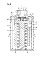
- FIG. 1 shows an exploded view of the essential components of the bleed valve in accordance with the invention
- FIG. 2 shows an axial sectional view of the bleed valve of FIG. 1 in the open position
- FIG. 3 shows an axial sectional view of the bleed valve of FIG. 1 in the closed position
- FIG. 4 shows an axial sectional view of the bleed valve of FIG. 1 at the commencement of a new opening procedure
- FIG. 5 shows a plan view of the floating body in accordance with a viewing direction V-V of FIG. 1 ;
- FIG. 6 shows a sectional view and partial view of the installation state of the bleed valve.
- the bleed valve consists of a cylindrical housing 1 which is closed off on the topside 1 ′′ by means of a preferably detachably inserted cover 2 , and of a generally likewise cylindrical floating body 3 which is disposed in the housing 1 in such a manner as to be able to move in the direction of the longitudinal axis 5 thereof.
- the floating body 3 can be guided in a non-rotatable manner inside the housing 1 in relation to the axis thereof by virtue of means which are known per se and are effective in a positive-locking manner.
- the housing 1 is provided on the topside with two mutually adjacent inlet orifices 4 and an outlet orifice 6 which extends in a coaxial manner with respect to the axis 5 is located in the cover 2 .
- the outlet orifice terminates on the outer side in a connecting piece 7 which is intended for the connection of an output line.
- the floating body 3 is supported in a manner known per se on the underside by way of a spring ( 32 ), on the base 1 ′ of the housing 1 , the mode of operation of the spring will be explained hereinafter.
- the floating body is provided with an annular-cylindrical chamber 8 which is open towards the underside 3 ′ of the floating body and extends substantially coaxially with respect to the axis 5 , wherein the spring is supported on the closed chamber base 9 of the chamber.
- the topside 3 ′′ of the floating body 3 is characterised by a ring-like arrangement of identically configured support fingers 10 which extends substantially coaxially with respect to the longitudinal axis 5 .
- the support fingers are integrally formed with the floating body 3 at uniform peripherally spaced intervals and protrude from the otherwise planar topside, which is radial in relation to the axis 5 , of the floating body.
- the reference numeral 11 designates an approximately conically-shaped guide mandrel which is located in a central position inside the ring-like arrangement and protrudes from the topside 3 ′′ and whose significance will be explained hereinafter.
- the guide mandrel extends a shorter distance axially in the direction towards the topside 1 ′′ than the support fingers 10 (see FIG. 2 ).
- the reference numeral 12 designates a support disc which in the peripheral region forms an annular step which is adjoined by an annular flange 13 .
- the support disc 12 comprises a central circular opening 14 , into which protrudes a cylindrical projection 16 which is formed integrally with a sealing disc 15 and by means of which the sealing disc is releasably connected to support disc 12 .
- the sealing disc 15 overlies the support disc 12 on its side facing away from the floating body 3 , i.e., the support disc has a counter surface 12 ′ for bearing against the sealing disc (see FIG. 2 ).
- the annular step of the support disc 12 encompasses the outer side of the arrangement of support fingers 10 and as a result thereof is subjected to a substantially axially directed guiding movement.
- a guiding or centring effect is also exerted by virtue of the guide mandrel 11 which protrudes into the open end 16 ′′ of the projection 16 facing towards the guide mandrel.
- the projection 16 also forms a continuous connection 16 ′ (a fluid conduit) between its open end 16 ′′ facing towards the guide mandrel 11 and its open end 16 ′′′ facing towards the valve seat 19 .
- the reference numerals 17 , 17 ′ designate two angular retainer elements which are attached in a mutually diametrically opposed manner to the floating body 3 , each having an abutment section 17 ′′ extending over the annular flange 13 , and which are intended to engage the top of the annular flange 13 as seen in FIG.
- the axial lengths of the retainer elements are different in dimension as shown. This means that the potential movements of the support disc 12 with respect to the two retainer elements 17 , 17 ′ accordingly will be different.
- the entire system consisting of a support disc and sealing disc 12 , 15 is subjected to an approximately cardanic suspension or mobility on or with respect to the floating body. Put another way, when the valve is in the fully closed position as shown in FIG.
- the support disc and sealing disc 12 , 15 can pivot about the mandrel 11 generally in any direction relative to the floating body 3 , i.e., pivotally move about two mutually perpendicular pivot axes 30 and 31 as shown in FIG. 5 .
- the pivot axis 30 passes through the retainer elements 17 , 17 ′ as shown.
- the abutment section 17 ′′ of the shorter retainer element 17 engages the support disk 12 before the longer retainer element 17 ′ does, thereby causing the pivot axis 30 to move to and be locked into an inclined pivot axis position 11 ′ relative to the longitudinal axis 5 .
- the other pivot axis 31 which is not affected by the retainer elements 17 , 17 ′ can remain perpendicular to the axis 5 and thus is not inclined.
- a non-inclined pivot axis 30 , 31 would be perpendicular to the longitudinal axis 5
- an inclined pivot axis 30 ( 11 ′) would not be perpendicular to the longitudinal axis 5 .
- this pivot axis causes the support disc and sealing disc 12 , 15 to be in the inclined position having a longitudinal axis 5 ′ relative to the housing longitudinal axis 5 . This allows the left side of the sealing disk 15 to pull away from the valve seat 19 before the right side as shown in FIG. 4 and as further described below.
- the outlet orifice 6 is characterised by a comparatively short tubular element 18 which extends coaxially with respect to the axis 5 and protrudes into the housing 1 and whose free end 19 ′ forms a valve seat 19 for the sealing disc 15 .
- a bleed valve of this type is intended for installation into the topside wall 20 of the fuel tank 21 of a vehicle.
- the fuel tank is filled to a permissible level 22 , so that in the type of installation shown where the housing 1 is located almost completely inside the tank, the inlet orifices 4 communicate merely with the head space 23 above the fluid.
- Other types of assembly of the bleed valve, in which the housing is located substantially outside the tank, are equally possible, wherein the inlet orifices have to be placed in different positions accordingly. However, this will be not be discussed further hereinafter.
- the position of the floating body 3 inside the bleed valve is determined according to the forces which act upon the floating body, namely a resilient force which acts upon its underside 3 ′, a lifting force in dependence upon the fluid level inside the housing 1 and a mass force, wherein the spring in conjunction with the material of the floating body 3 is selected with the proviso that in the open position of the valve as illustrated in FIG. 2 which is normally characterised by the absence of a lifting force, the resilient force is overcome by the mass force of the floating body 3 including the parts which are connected thereto and the floating body 3 sinks to the base 1 ′ of the housing 1 .
- a continuous connection (ventilation flow path) is established between the inlet orifices 4 and the outlet orifice 6 , so that it is possible to ventilate and similarly bleed the tank substantially without any hindrance.
- the sealing disc 15 in this position thus does not have any contact with the valve seat and the support disc 12 lies on the underside on the guide mandrel 11 which at the same time exerts a centring effect upon the sealing disc or the support disc.
- a radial guiding effect is also exerted by the support fingers 10 , the radial outer sides of which are disposed at a small spacing with respect to the radial inner side of the annular step of the support disc 12 .
- FIGS. 3 , 4 of the drawings in which functional elements which correspond to those illustrated in FIGS. 1 , 2 , 5 or 6 are designated with like reference numerals so as to obviate any repetition of the description in this respect.
- the closed state of the bleed valve as illustrated in FIG. 3 is characterised by virtue of the fact that e.g. under the influence of a lifting force which is effective in addition to the resilient force and the mass forces, the floating body 3 has moved inside the housing 1 upwardly in the direction of the cover 2 , so that the sealing disc 15 lies against the valve seat 19 .
- the stabilising effect of the support disc 12 provides a reliable and reproducible sealing effect.
- the projection 16 is urged into sealing abutment against the guide mandrel 11 .
- the retainer elements 17 , 17 ′ do not function when the valve is in this position.
- the closed state of the bleed valve can occur as a result of the tank being overfilled or in the event of an orientation of the position of the axis of the valve which deviates substantially from the vertical orientation and which can be instigated by corresponding vehicle movements, in particular swinging movements, the negotiation of turns with a change in orientation, but also as a result of an accident, e.g. a vehicle overturning.
- the cardanic suspension of the sealing disc 15 serves to provide a uniform sealing effect, to an extent dependent upon the different dimensions of the retainer elements 17 , 17 ′, along the valve seat 19 and the guide mandrel 11 even when the valve is in an inclined position, since any offset of the axes of the floating body 3 and of the housing 1 can be compensated for.
- the state illustrated in FIG. 4 where the valve starts to open anew following on from a closed state is characterised by the fact that the sealing disc 15 becomes gradually detached from the valve seat 19 , wherein the detachment procedure is initiated as a result of the movement of the floating body 3 in the direction towards the base 1 ′ of the housing 1 by virtue of the retainer element 17 which in axial terms is relatively shorter, and correspondingly the valve begins to open at a point on the periphery of the valve seat, so that the sealing disc 15 assumes a temporary inclined position with respect to the axis 5 .
- the expenditure of energy required for the detachment can be kept low in this manner, i.e., it is easier to unseat the sealing disc from the valve seat.
- the detachment procedure also initially causes the projection 16 to lift off from the guide mandrel 11 , with the consequence that starting from the inlet orifices 4 a continuous connection 16 ′ is established via the projection 16 to the outlet orifice, thus further facilitating the detachment procedure.
- a bleed valve of this type in particular its housing, can be disposed in the wall of the fuel tank, in this case it can form a supporting structure on the outer side or can even protrude at least partially into the tank.
- a particular holding device in which the housing is received and which provides a connection to the outlet orifice, wherein this holding device is held on a pump unit or another component or is disposed together with an independent line system on the inner side of the tank.
- a structural element intended for use in a fuel tank is provided with the bleed valve in accordance with the invention and is characterised by a simple structural design and satisfies all operational requirements in a reliable and reproducible manner.
Landscapes
- Engineering & Computer Science (AREA)
- Life Sciences & Earth Sciences (AREA)
- Sustainable Development (AREA)
- Sustainable Energy (AREA)
- Chemical & Material Sciences (AREA)
- Combustion & Propulsion (AREA)
- Transportation (AREA)
- Mechanical Engineering (AREA)
- Cooling, Air Intake And Gas Exhaust, And Fuel Tank Arrangements In Propulsion Units (AREA)
- Self-Closing Valves And Venting Or Aerating Valves (AREA)
- Float Valves (AREA)
Applications Claiming Priority (4)
| Application Number | Priority Date | Filing Date | Title |
|---|---|---|---|
| DE20319920.0 | 2003-12-23 | ||
| DE2003219920 DE20319920U1 (de) | 2003-12-23 | 2003-12-23 | Entlüftungsventil |
| DE20319920U | 2003-12-23 | ||
| PCT/EP2004/011194 WO2005065977A1 (fr) | 2003-12-23 | 2004-10-07 | Soupape de purge |
Publications (2)
| Publication Number | Publication Date |
|---|---|
| US20090107561A1 US20090107561A1 (en) | 2009-04-30 |
| US7770593B2 true US7770593B2 (en) | 2010-08-10 |
Family
ID=34178095
Family Applications (1)
| Application Number | Title | Priority Date | Filing Date |
|---|---|---|---|
| US10/596,682 Expired - Fee Related US7770593B2 (en) | 2003-12-23 | 2004-10-07 | Bleed valve |
Country Status (5)
| Country | Link |
|---|---|
| US (1) | US7770593B2 (fr) |
| EP (1) | EP1697157B9 (fr) |
| DE (2) | DE20319920U1 (fr) |
| ES (1) | ES2291949T3 (fr) |
| WO (1) | WO2005065977A1 (fr) |
Cited By (8)
| Publication number | Priority date | Publication date | Assignee | Title |
|---|---|---|---|---|
| US20090084449A1 (en) * | 2007-10-02 | 2009-04-02 | Piolax Inc. | Float valve device |
| US20150144204A1 (en) * | 2012-12-24 | 2015-05-28 | Eaton Corporation | Valve assembly for a tank of a vehicle |
| US20160201819A1 (en) * | 2013-08-09 | 2016-07-14 | Kautex Textron Gmbh & Co. Kg | Universal shutoff valve |
| US9884550B2 (en) | 2012-07-12 | 2018-02-06 | Eaton Corporation | Flapper valve with guide legs |
| US10245941B2 (en) | 2011-10-26 | 2019-04-02 | Kautex Textron Gmbh & Co. Kg | Vent valve |
| US11001138B2 (en) * | 2016-08-18 | 2021-05-11 | Nifco Korea Inc. | Fill limit vent valve for fuel tank |
| US20230025882A1 (en) * | 2021-07-23 | 2023-01-26 | Toyoda Gosei Co., Ltd. | Fluid limit vent valve with splash prevention |
| US20240159324A1 (en) * | 2021-02-11 | 2024-05-16 | Bemis Manufacturing Company | Rollover vent valve assembly |
Families Citing this family (3)
| Publication number | Priority date | Publication date | Assignee | Title |
|---|---|---|---|---|
| FR2886367B1 (fr) * | 2005-05-24 | 2008-12-26 | Inergy Automotive Systems Res | Clapet pour circuit de mise a l'air d'un reservoir a liquide |
| DE102013201237A1 (de) | 2013-01-25 | 2014-07-31 | Veritas Ag | Entlüftungsventil |
| CN103470832B (zh) * | 2013-09-23 | 2015-10-14 | 孙达立 | 一种溢流切断阀 |
Citations (12)
| Publication number | Priority date | Publication date | Assignee | Title |
|---|---|---|---|---|
| US4753262A (en) | 1987-02-06 | 1988-06-28 | G.T. Products, Inc. | Fuel system vent valve having roll-over closure with improved re-opening action for venting |
| US4982757A (en) | 1988-10-20 | 1991-01-08 | Toyoda Gosei Co., Ltd. | Fuel cutoff valve |
| US5439023A (en) | 1994-04-11 | 1995-08-08 | Kabushiki Kaisha Mikuni | Shut-off valve for liquid fuel |
| US5573030A (en) * | 1993-12-29 | 1996-11-12 | Kyosan Denki Co., Ltd. | Stop valve |
| US5755252A (en) | 1994-08-24 | 1998-05-26 | G.T. Products, Inc. | Control valve with two-stage shutoff and peel away opening action |
| DE69601135T2 (de) | 1995-01-25 | 1999-05-20 | Raviv Precision Injection Molding, Halutza | Überrollentlüftungsventil |
| US5944044A (en) * | 1996-05-10 | 1999-08-31 | Stant Manufacturing Inc. | Tank venting control system |
| US5950655A (en) * | 1997-02-04 | 1999-09-14 | G.T. Products, Inc. | Mechanical seal ORVR system and control valve |
| US5960816A (en) * | 1997-03-26 | 1999-10-05 | G.T. Products, Inc. | Adjustable length vent valve system for fuel tanks |
| US6035884A (en) | 1997-09-16 | 2000-03-14 | Stant Manufacturing Inc. | Liquid fuel baffle for vent apparatus |
| US6240950B1 (en) | 1998-08-27 | 2001-06-05 | Stant Manufacturing Inc. | Vapor control valve with bypass circuit |
| US20030098063A1 (en) * | 2001-11-29 | 2003-05-29 | Eishin Mori | Outflow-limiting device of fuel tank |
-
2003
- 2003-12-23 DE DE2003219920 patent/DE20319920U1/de not_active Expired - Lifetime
-
2004
- 2004-10-07 EP EP04790167A patent/EP1697157B9/fr not_active Expired - Lifetime
- 2004-10-07 US US10/596,682 patent/US7770593B2/en not_active Expired - Fee Related
- 2004-10-07 WO PCT/EP2004/011194 patent/WO2005065977A1/fr not_active Ceased
- 2004-10-07 ES ES04790167T patent/ES2291949T3/es not_active Expired - Lifetime
- 2004-10-07 DE DE200450004683 patent/DE502004004683D1/de not_active Expired - Lifetime
Patent Citations (12)
| Publication number | Priority date | Publication date | Assignee | Title |
|---|---|---|---|---|
| US4753262A (en) | 1987-02-06 | 1988-06-28 | G.T. Products, Inc. | Fuel system vent valve having roll-over closure with improved re-opening action for venting |
| US4982757A (en) | 1988-10-20 | 1991-01-08 | Toyoda Gosei Co., Ltd. | Fuel cutoff valve |
| US5573030A (en) * | 1993-12-29 | 1996-11-12 | Kyosan Denki Co., Ltd. | Stop valve |
| US5439023A (en) | 1994-04-11 | 1995-08-08 | Kabushiki Kaisha Mikuni | Shut-off valve for liquid fuel |
| US5755252A (en) | 1994-08-24 | 1998-05-26 | G.T. Products, Inc. | Control valve with two-stage shutoff and peel away opening action |
| DE69601135T2 (de) | 1995-01-25 | 1999-05-20 | Raviv Precision Injection Molding, Halutza | Überrollentlüftungsventil |
| US5944044A (en) * | 1996-05-10 | 1999-08-31 | Stant Manufacturing Inc. | Tank venting control system |
| US5950655A (en) * | 1997-02-04 | 1999-09-14 | G.T. Products, Inc. | Mechanical seal ORVR system and control valve |
| US5960816A (en) * | 1997-03-26 | 1999-10-05 | G.T. Products, Inc. | Adjustable length vent valve system for fuel tanks |
| US6035884A (en) | 1997-09-16 | 2000-03-14 | Stant Manufacturing Inc. | Liquid fuel baffle for vent apparatus |
| US6240950B1 (en) | 1998-08-27 | 2001-06-05 | Stant Manufacturing Inc. | Vapor control valve with bypass circuit |
| US20030098063A1 (en) * | 2001-11-29 | 2003-05-29 | Eishin Mori | Outflow-limiting device of fuel tank |
Cited By (12)
| Publication number | Priority date | Publication date | Assignee | Title |
|---|---|---|---|---|
| US20090084449A1 (en) * | 2007-10-02 | 2009-04-02 | Piolax Inc. | Float valve device |
| US8844557B2 (en) * | 2007-10-02 | 2014-09-30 | Piolax Inc. | Float valve device |
| US10245941B2 (en) | 2011-10-26 | 2019-04-02 | Kautex Textron Gmbh & Co. Kg | Vent valve |
| US9884550B2 (en) | 2012-07-12 | 2018-02-06 | Eaton Corporation | Flapper valve with guide legs |
| US20150144204A1 (en) * | 2012-12-24 | 2015-05-28 | Eaton Corporation | Valve assembly for a tank of a vehicle |
| US10041450B2 (en) * | 2012-12-24 | 2018-08-07 | Eaton Intelligent Power Limited | Valve assembly for a tank of a vehicle |
| US20160201819A1 (en) * | 2013-08-09 | 2016-07-14 | Kautex Textron Gmbh & Co. Kg | Universal shutoff valve |
| US10753250B2 (en) * | 2013-08-09 | 2020-08-25 | Kautex Textron Gmbh & Co. Kg | Universal shutoff valve |
| US11001138B2 (en) * | 2016-08-18 | 2021-05-11 | Nifco Korea Inc. | Fill limit vent valve for fuel tank |
| US20240159324A1 (en) * | 2021-02-11 | 2024-05-16 | Bemis Manufacturing Company | Rollover vent valve assembly |
| US12297921B2 (en) * | 2021-02-11 | 2025-05-13 | Bemis Manufacturing Company | Rollover vent valve assembly |
| US20230025882A1 (en) * | 2021-07-23 | 2023-01-26 | Toyoda Gosei Co., Ltd. | Fluid limit vent valve with splash prevention |
Also Published As
| Publication number | Publication date |
|---|---|
| EP1697157B1 (fr) | 2007-08-15 |
| WO2005065977A1 (fr) | 2005-07-21 |
| ES2291949T3 (es) | 2008-03-01 |
| US20090107561A1 (en) | 2009-04-30 |
| DE20319920U1 (de) | 2005-02-03 |
| EP1697157B9 (fr) | 2008-01-02 |
| DE502004004683D1 (de) | 2007-09-27 |
| EP1697157A1 (fr) | 2006-09-06 |
Similar Documents
| Publication | Publication Date | Title |
|---|---|---|
| KR100907167B1 (ko) | 증기 벤트 밸브 조립체 및 증기 벤트 제어 방법 | |
| EP1295747B1 (fr) | Vanne de purge actionnée par un flotteur pour vapeur de carburant d'un réservoir | |
| US20090107561A1 (en) | Bleed Valve | |
| US6216730B1 (en) | Filter for diaphragm-type flush valve | |
| JP5232578B2 (ja) | ピボット作動型スリーブバルブ | |
| EP0697994B1 (fr) | Ensemble sonde etanche d'actuateur destine a un poste de distribution d'eau en bouteille | |
| KR101479116B1 (ko) | 플로트 밸브 장치 | |
| CA2214303C (fr) | Garniture de poignee de robinet de c.w. a joint d'etancheite | |
| GB2377742A (en) | Fuel tank vent valve with lubricious sealing surface | |
| MXPA04006174A (es) | Conjunto de valvula de una via para un cuello de llenado y metodo de instalar un cuello de llenado. | |
| US7543597B2 (en) | Vent valve assembly with lever arrangement | |
| JP2009542525A (ja) | 乗物のタンクにディーゼル燃料を注入するための燃料注入口組立体 | |
| US7614417B2 (en) | Air release valve for fuel tank of a motor vehicle | |
| CA2435348A1 (fr) | Dispositif de decompression a joint d'etancheite monobloc | |
| CN109312697B (zh) | 燃料切断阀 | |
| GB2164128A (en) | Air admittance valves | |
| CA2534232A1 (fr) | Couvercle de contenant de distribution | |
| US4460013A (en) | Pressure-vacuum vent | |
| JPS6128929Y2 (fr) | ||
| CN222880339U (zh) | 液体流量控制阀 | |
| JP2007016891A (ja) | エア抜き弁 | |
| KR102591729B1 (ko) | 스템 밀봉 케이싱을 구비한 라이징 스템 볼 밸브 | |
| RU2344955C1 (ru) | Запорное устройство системы водоснабжения | |
| JP3305907B2 (ja) | 液体遮断弁 | |
| WO2009058050A1 (fr) | Dispositif de fermeture d'un système d'alimentation en eau |
Legal Events
| Date | Code | Title | Description |
|---|---|---|---|
| AS | Assignment |
Owner name: PNC BANK NATIONAL ASSOCIATION, PENNSYLVANIA Free format text: SECURITY AGREEMENT;ASSIGNORS:AKRION, INC.;GOLDFINGER TECHNOLOGIES, LLC;REEL/FRAME:017619/0512 Effective date: 20050805 |
|
| XAS | Not any more in us assignment database |
Free format text: SEE RECORDING AT REEL 017619 FRAME 0512. (DOCUMENT RECORDED OVER TO CORRECT THE RECORDATION DATE FROM 05/10/2006 TO 09/30/2005);ASSIGNORS:AKRION, INC;GOLDFINGER TECHNOLOGIES, LLC;REEL/FRAME:017606/0168 |
|
| AS | Assignment |
Owner name: A. KAYSER AUTOMOTIVE SYSTEMS GMBH, GERMANY Free format text: ASSIGNMENT OF ASSIGNORS INTEREST;ASSIGNOR:MOSES, ERHARD;REEL/FRAME:018078/0022 Effective date: 20060728 |
|
| REMI | Maintenance fee reminder mailed | ||
| LAPS | Lapse for failure to pay maintenance fees | ||
| STCH | Information on status: patent discontinuation |
Free format text: PATENT EXPIRED DUE TO NONPAYMENT OF MAINTENANCE FEES UNDER 37 CFR 1.362 |
|
| STCH | Information on status: patent discontinuation |
Free format text: PATENT EXPIRED DUE TO NONPAYMENT OF MAINTENANCE FEES UNDER 37 CFR 1.362 |
|
| FP | Lapsed due to failure to pay maintenance fee |
Effective date: 20140810 |