US7775764B2 - Gas turbine engine rotor ventilation arrangement - Google Patents
Gas turbine engine rotor ventilation arrangement Download PDFInfo
- Publication number
- US7775764B2 US7775764B2 US11/702,589 US70258907A US7775764B2 US 7775764 B2 US7775764 B2 US 7775764B2 US 70258907 A US70258907 A US 70258907A US 7775764 B2 US7775764 B2 US 7775764B2
- Authority
- US
- United States
- Prior art keywords
- rotor
- cooling air
- cavity
- bore
- assembly
- Prior art date
- Legal status (The legal status is an assumption and is not a legal conclusion. Google has not performed a legal analysis and makes no representation as to the accuracy of the status listed.)
- Active, expires
Links
Images




Classifications
-
- F—MECHANICAL ENGINEERING; LIGHTING; HEATING; WEAPONS; BLASTING
- F01—MACHINES OR ENGINES IN GENERAL; ENGINE PLANTS IN GENERAL; STEAM ENGINES
- F01D—NON-POSITIVE DISPLACEMENT MACHINES OR ENGINES, e.g. STEAM TURBINES
- F01D5/00—Blades; Blade-carrying members; Heating, heat-insulating, cooling or antivibration means on the blades or the members
- F01D5/02—Blade-carrying members, e.g. rotors
- F01D5/08—Heating, heat-insulating or cooling means
- F01D5/081—Cooling fluid being directed on the side of the rotor disc or at the roots of the blades
- F01D5/082—Cooling fluid being directed on the side of the rotor disc or at the roots of the blades on the side of the rotor disc
-
- F—MECHANICAL ENGINEERING; LIGHTING; HEATING; WEAPONS; BLASTING
- F01—MACHINES OR ENGINES IN GENERAL; ENGINE PLANTS IN GENERAL; STEAM ENGINES
- F01D—NON-POSITIVE DISPLACEMENT MACHINES OR ENGINES, e.g. STEAM TURBINES
- F01D5/00—Blades; Blade-carrying members; Heating, heat-insulating, cooling or antivibration means on the blades or the members
- F01D5/02—Blade-carrying members, e.g. rotors
- F01D5/08—Heating, heat-insulating or cooling means
- F01D5/085—Heating, heat-insulating or cooling means cooling fluid circulating inside the rotor
-
- F—MECHANICAL ENGINEERING; LIGHTING; HEATING; WEAPONS; BLASTING
- F05—INDEXING SCHEMES RELATING TO ENGINES OR PUMPS IN VARIOUS SUBCLASSES OF CLASSES F01-F04
- F05D—INDEXING SCHEME FOR ASPECTS RELATING TO NON-POSITIVE-DISPLACEMENT MACHINES OR ENGINES, GAS-TURBINES OR JET-PROPULSION PLANTS
- F05D2260/00—Function
- F05D2260/20—Heat transfer, e.g. cooling
-
- F—MECHANICAL ENGINEERING; LIGHTING; HEATING; WEAPONS; BLASTING
- F05—INDEXING SCHEMES RELATING TO ENGINES OR PUMPS IN VARIOUS SUBCLASSES OF CLASSES F01-F04
- F05D—INDEXING SCHEME FOR ASPECTS RELATING TO NON-POSITIVE-DISPLACEMENT MACHINES OR ENGINES, GAS-TURBINES OR JET-PROPULSION PLANTS
- F05D2270/00—Control
- F05D2270/01—Purpose of the control system
- F05D2270/11—Purpose of the control system to prolong engine life
- F05D2270/112—Purpose of the control system to prolong engine life by limiting temperatures
Definitions
- This invention relates to ventilation of rotor assemblies in gas turbine engines, and in particular to cooling flow paths in such rotor assemblies.
- the object of the present invention is to provide an improved cooling arrangement for the cavities between rotors in turbine and compressor assemblies of gas turbine engines.
- a rotor assembly for a gas turbine engine, the rotor assembly comprises at least two rotors defining a cavity therebetween; a first rotor defines a cooling air inlet in its radially inward portion, characterized in that a second rotor defines a cooling air outlet in its radially outward portion, such that the cooling air passes radially outwardly through the cavity.
- the rotor assembly comprises a third rotor stage defining a second cavity with the second stage, the cooling air that passes through the outlet then passes into and radially inwardly through the second cavity to pass through the bore of the third rotor.
- the rotor assembly comprises a fourth rotor defining a third cavity with the third stage, the cooling air that passes through the bore of the third stage then passes into and radially outwardly through the third cavity to pass through a cooling air outlet defined in a radially outward portion of the fourth stage.
- the rotor assembly comprises a fifth rotor defining a fourth cavity with the first rotor, at least one inlet is defined in a shroud of the first or fifth rotors, the cooling enters the fourth cavity via the inlet and passes radially inwardly through the fourth cavity and into the first cavity via the bore of the first rotor.
- the fifth rotor defines a bore and the cooling entering the fourth cavity passes through the bore of the fifth rotor.
- the rotor assembly comprises a sixth rotor defining a fifth cavity with the fifth rotor, at least one outlet is defined in the radially outer part of the sixth rotor, the cooling air entering the fifth cavity passes radially outwardly between the bore of the fifth rotor and the outlet.
- the cooling air passes in a generally rearward direction through the rotor assembly.
- the cooling air passes in a generally forward direction through the rotor assembly.
- the cooling air passing the first, second, third and fourth rotors passes in a rearward direction and the cooling air passing the fifth and sixth rotors passes in a forward direction.
- the cooling air outlet is angled in the axial direction, preferably, the cooling air outlet is angled tangentially also such that the cooling air has a component of velocity in the tangential direction and further in the direction of rotation of the disc.
- cooling air outlet is angled tangentially in the opposite direction of rotation of the disc.
- At least one of the cooling air outlets is angled radially such that the cooling air has a component of velocity in the radial direction being angled radially inwardly or radially outwardly.
- the cooling air inlet is a bore of the first rotor.
- a shaft passes through the bore of at least some of the rotor stages of the rotor assembly.
- a seal is provided between the shaft and any one or more of the group comprising the second, the fourth and the sixth rotors.
- the seal is a labyrinth seal.
- the seal comprises a small clearance between the bore of the rotor and the shaft such that the airflow into the respective cavity preferentially passes through the cooling air outlet.
- the assembly is a compressor assembly.
- the assembly is a turbine assembly.
- a gas turbine engine comprises a rotor assembly as claimed in any one of the preceding paragraphs.
- FIG. 1 is a sectional side view of a gas turbine engine.
- FIG. 2 is a sectional side view of part of a prior art compressor of the engine shown in FIG. 1 .
- FIG. 3 is a sectional side view of part of a second prior art compressor of the engine shown in FIG. 1 .
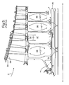
- FIG. 4 is a sectional side view of part of a first embodiment of a ventilation arrangement of the compressor of the engine shown in FIG. 1 in accordance with the present invention.
- FIG. 5 is a sectional side view of part of a second embodiment of a ventilation arrangement of the compressor of the engine shown in FIG. 1 in accordance with the present invention.
- FIG. 6 is a view (arrow C in FIG. 4 ) on a part of a rotor disc of the present invention.
- a gas turbine engine is generally indicated at 10 and comprises, in axial flow (arrow A) series, an air intake 11 , a propulsive fan 12 , an intermediate pressure compressor 13 , a high pressure compressor 14 , combustion equipment 15 , a high pressure turbine 16 , an intermediate pressure turbine 17 , a low pressure turbine 18 and an exhaust nozzle 19 .
- the gas turbine engine 10 works in the conventional manner so that air entering the intake 11 is accelerated by the fan to produce two air flows: a first air flow A into the intermediate pressure compressor 13 and a second air flow B which provides propulsive thrust.
- the intermediate pressure compressor 13 compresses the airflow A directed into it before delivering that air to the high pressure compressor 14 where further compression takes place.
- the compressed air exhausted from the high-pressure compressor 14 is directed into the combustion equipment 15 where it is mixed with fuel and the mixture combusted.
- the resultant hot combustion products then expand through, and thereby drive, the high, intermediate and low-pressure turbines 16 , 17 and 18 before being exhausted through the nozzle 19 to provide additional propulsive thrust.
- the high, intermediate and low-pressure turbines 16 , 17 and 18 respectively drive the high and intermediate pressure compressors 14 and 13 and the fan 12 by suitable interconnecting shafts.
- FIGS. 2-5 show the intermediate compressor 13 in more detail; the compressor 13 comprises a series of rotating discs or rotors 31 , 32 , 33 , 34 , 35 in downstream or rearward sequence relative to the main airflow A through the engine 10 .
- the discs 31 - 35 define cavities 36 - 39 therebetween respectively.
- Each rotating disc 31 - 35 carries an annular array of radially extending compressor blades 40 - 44 respectively at their outer shrouds 52 , which are interposed with cooperating stator vanes 45 - 49 .
- the compressor 13 works in conventional manner with each successive rotor stage further compressing the main airflow A.
- the compressor 13 is driven by the intermediate turbine 17 via interconnecting shaft 25 , which rotates about a main engine axis X-X.
- FIG. 2 shows a ventilating or cooling airflow C entering the compressor 13 through one of a series of ventilation holes 50 defined within the upstream disc 31 .
- the airflow C passes through the compressor 13 between the discs' bores 70 and the shaft 25 .
- a portion of the flow C′ circulates within each cavity 36 - 39 successively.
- a second prior art ventilation arrangement comprises one of the shrouds 52 defining an annular array of cooling air inlet holes 54 .
- Cooling airflow D enters cavity 37 flowing radially inwardly towards the engine centre line X-X and then flows upstream and downstream (relative to main gas flow A) through the compressor 13 between the discs' bores 70 and the shaft 25 .
- a portion of the flow D′ circulates within each cavity 36 and 38 , 39 successively. This radial flow confers an improvement over the previous prior art arrangement for the thermal response of the discs 32 , 33 (only).
- Tip clearance refers to the gap between a blade tip 58 and a (compressor) casing 56 . Tip clearances are affected by thermal expansions and contractions within the rotor assemblies (e.g. 32 and 40 ) as well as rotational centrifugal forces. Thus, achieving greater control and prediction of the thermal characteristics of any compressor or turbine rotor stage, better control of and reduction of the tip clearances will be possible.
- the object of the present invention is therefore to provide a ventilation/cooling arrangement that is more predictable and efficient at removing heat from the discs/rotor assemblies of compressors and turbines.
- annular arrays of holes 66 , 67 are introduced in a radially outer part 74 of alternate discs 32 , 34 diaphragms 65 . Seals 72 are placed between the bores of these discs 32 , 34 and the shaft 25 .
- an airflow E entering through the array of ventilation/cooling holes 50 flows through disc bore 31 into and radially through cavity 36 , passes through hole 66 in diaphragm 65 , radially inwardly to pass through disc bore 70 and so on through cavity 38 , holes 67 and cavity 39 in a substantially serpentine flow pattern.
- Each rotor disc 31 - 35 and 81 - 85 ( FIGS. 4 and 5 ) comprises a radially outer part 74 and a radially inner part 76 .
- the inner and outer parts of the rotors merely indicate that cooling air inlets and outlets are radially spaced relative to one another. It is preferable that the inlets and outlets are positioned as radially far apart as practical.
- the airflow passing through the bores 70 of disc 31 and 33 may alternatively flow through other holes in a radially inner part 76 of the discs.
- the present invention relates to a rotor assembly comprising at least two rotors 31 , 32 which define a cavity 36 .
- the first rotor 31 defines a cooling air inlet 70 in its radially inward portion 76 and the second rotor 32 defines a cooling air outlet 66 in its radially outward portion 74 , such that the cooling air passes radially outwardly through the cavity 36 .
- the rotor assembly further comprises the third rotor stage 33 defining a second cavity 37 with the second stage 32 , the cooling air that passes through the outlet 66 then passes into and radially inwardly through the second cavity 37 to pass through the bore 70 of the third rotor 33 .
- the rotor assembly comprises a fourth rotor 34 defining the third cavity 38 with the third stage 33 .
- the cooling air that passes through the bore 70 of the third stage 33 then passes into and radially outwardly through the third cavity 38 to pass through a cooling air outlet 67 defined in a radially outward portion 74 of the fourth stage 34 .
- this alternative embodiment differs in that cooling air is bled from a mid-stage of the compressor 13 .
- an array of inlet holes 54 is provided in the shroud 52 of the discs 82 , 83 and are similar to 32 , 33 described with reference to FIG. 3 .
- a cooling airflow F passes through the inlet holes 54 into and radially inwardly towards the shaft 25 .
- the airflow F splits into two airflows, F 1 and F 2 , in which airflow F 1 passes rearwards through the bore of rotor 83 , similarly to the bore of rotor 31 in FIG.
- this embodiment is equivalent to the FIG. 4 embodiment from the ‘first’ rotor 83 / 31 rearward and may comprise more rotor stages than is shown.
- the rotor assembly of FIG. 5 also comprises a fourth rotor 82 , positioned forward of the first rotor 83 .
- the fourth rotor defines a fourth cavity 86 with the first rotor 83 and the array of inlet holes 54 is defined in the shrouds 52 of the first and/or fourth rotors 83 , 82 .
- the cooling airflow F splits into the rearward airflow F 1 and forward airflow F 2 , F 2 entering the fourth cavity 86 via the inlet 54 and passes radially inwardly through the fourth cavity 86 and into the third cavity 87 via the bore 70 of the fourth rotor 82 .
- the fourth rotor 82 defines a bore 70 and the cooling entering the fourth cavity 86 also passes through the bore 70 of the fourth rotor 82 .
- the rotor assembly may further comprise a fifth rotor 81 defining a third cavity 87 with the fourth rotor 82 .
- An array of outlets 68 is defined in the radially outer part 74 of the fifth rotor 81 , the cooling air entering the third cavity 87 passes radially outwardly between the bore 70 of the fourth rotor 82 and the outlet 68 .
- heat transfer coefficients can be calculated with greater confidence for use in mathematical models for calculating thermal characteristics of the compressor or turbine.
- the amount of cooling through-flow can be metered by suitable sizing of the inlet and outlet holes in the shrouds and diaphragms enabling the thermal response of the rotor assembly to be optimized and reduce tip clearances, particularly at transient engine conditions, e.g. between say take-off and cruise operating engine speeds, but also at steady state engine running. Reducing tip clearances reduces the amount of over-tip leakage thereby improving engine efficiency.
- the optimum source of cooling air can be utilised (normally but not necessarily the coolest), the total air consumption is minimised. Still further by allowing better control of tip clearances, significant improvement in compressor efficiency can be realised
- a further advantage of the present invention is the improvement of the thermal response of rotor discs thereby increasing the life of the rotor components. Alternatively, the use of less capable and cheaper materials may be possible.
- the outlet 66 ′ through which cooling air flow E passes into the second cavity 37 is formed at an angle such that the air is given a tangential component of velocity.
- the outlet 66 ′ is angled forwardly such that the air flow E is in the direction of rotation of the disc 65 .
- This tangential angling of the outlet 66 ′ increases the relative velocity between the disc 65 and the cooling air E in the cavity 37 , thereby improving heat removal from the disc 65 .
- outlets may be angled in the opposite direction to rotation of the disc 65 to increase the relative velocity between cooling air and disc where such a regime exists.
- outlet 66 ′′ may be angled radially such that the cooling airflow has a radial component of velocity, helping direct the cooling air in the direction of the through-flow.
- outlet 66 ′′ is angled both radially inwardly and tangentially.
Landscapes
- Engineering & Computer Science (AREA)
- Mechanical Engineering (AREA)
- General Engineering & Computer Science (AREA)
- Turbine Rotor Nozzle Sealing (AREA)
- Structures Of Non-Positive Displacement Pumps (AREA)
Applications Claiming Priority (2)
| Application Number | Priority Date | Filing Date | Title |
|---|---|---|---|
| GB0603030.8 | 2006-02-15 | ||
| GBGB0603030.8A GB0603030D0 (en) | 2006-02-15 | 2006-02-15 | Gas turbine engine rotor ventilation arrangement |
Publications (2)
| Publication Number | Publication Date |
|---|---|
| US20070189890A1 US20070189890A1 (en) | 2007-08-16 |
| US7775764B2 true US7775764B2 (en) | 2010-08-17 |
Family
ID=36141874
Family Applications (1)
| Application Number | Title | Priority Date | Filing Date |
|---|---|---|---|
| US11/702,589 Active 2028-11-16 US7775764B2 (en) | 2006-02-15 | 2007-02-06 | Gas turbine engine rotor ventilation arrangement |
Country Status (3)
| Country | Link |
|---|---|
| US (1) | US7775764B2 (fr) |
| EP (1) | EP1820936B1 (fr) |
| GB (1) | GB0603030D0 (fr) |
Cited By (14)
| Publication number | Priority date | Publication date | Assignee | Title |
|---|---|---|---|---|
| US20090304495A1 (en) * | 2007-07-06 | 2009-12-10 | Snecma | Device for supplying ventilation air to the low pressure blades of a gas turbine engine |
| RU2506436C2 (ru) * | 2012-02-06 | 2014-02-10 | Федеральное государственное унитарное предприятие "Центральный институт авиационного моторостроения имени П.И. Баранова" | Устройство оптимизации радиальных зазоров многоступенчатого осевого компрессора авиационного газотурбинного двигателя |
| US20160069193A1 (en) * | 2014-09-04 | 2016-03-10 | United Technologies Corporation | Coolant flow redirection component |
| US20160076379A1 (en) * | 2014-09-12 | 2016-03-17 | United Technologies Corporation | Turbomachine rotor thermal regulation systems |
| US20160215792A1 (en) * | 2013-10-02 | 2016-07-28 | United Technologies Corporation | Gas Turbine Engine With Compressor Disk Deflectors |
| US9670780B2 (en) | 2013-03-11 | 2017-06-06 | United Technologies Corporation | Tie shaft flow trip |
| US10030582B2 (en) | 2015-02-09 | 2018-07-24 | United Technologies Corporation | Orientation feature for swirler tube |
| US10161251B2 (en) | 2014-09-12 | 2018-12-25 | United Technologies Corporation | Turbomachine rotors with thermal regulation |
| US10316681B2 (en) * | 2016-05-31 | 2019-06-11 | General Electric Company | System and method for domestic bleed circuit seals within a turbine |
| US20200165935A1 (en) * | 2015-10-23 | 2020-05-28 | Mitsubishi Hitachi Power Systems, Ltd. | Compressor rotor, gas turbine rotor provided therewith, and gas turbine |
| US11143041B2 (en) | 2017-01-09 | 2021-10-12 | General Electric Company | Turbine have a first and second rotor disc and a first and second cooling fluid conduit wherein the second cooling fluid conduit is extended through an annular axially extended bore having a radially outer extent defined by a radially innermost surface of the rotor discs |
| US11215056B2 (en) | 2020-04-09 | 2022-01-04 | Raytheon Technologies Corporation | Thermally isolated rotor systems and methods |
| US11499479B2 (en) | 2017-08-31 | 2022-11-15 | General Electric Company | Air delivery system for a gas turbine engine |
| US11892083B2 (en) | 2022-04-06 | 2024-02-06 | Rtx Corporation | Piston seal ring |
Families Citing this family (14)
| Publication number | Priority date | Publication date | Assignee | Title |
|---|---|---|---|---|
| JP2010019190A (ja) * | 2008-07-11 | 2010-01-28 | Toshiba Corp | 蒸気タービンおよび蒸気タービンの冷却方法 |
| US8087871B2 (en) * | 2009-05-28 | 2012-01-03 | General Electric Company | Turbomachine compressor wheel member |
| US8376689B2 (en) * | 2010-04-14 | 2013-02-19 | General Electric Company | Turbine engine spacer |
| US9068507B2 (en) * | 2011-11-16 | 2015-06-30 | General Electric Company | Compressor having purge circuit and method of purging |
| US9234463B2 (en) * | 2012-04-24 | 2016-01-12 | United Technologies Corporation | Thermal management system for a gas turbine engine |
| US20150362463A1 (en) | 2013-03-01 | 2015-12-17 | Kyocera Corporation | Sensor |
| US10280792B2 (en) | 2014-02-21 | 2019-05-07 | United Technologies Corporation | Bore basket for a gas powered turbine |
| DE102015219022A1 (de) | 2015-10-01 | 2017-04-06 | Rolls-Royce Deutschland Ltd & Co Kg | Strömungsleitvorrichtung und Turbomaschine mit mindestens einer Strömungsleitvorrichtung |
| US10760494B2 (en) * | 2018-03-18 | 2020-09-01 | Raytheon Technologies Corporation | Telescoping bore basket for gas turbine engine |
| US10808627B2 (en) | 2018-03-26 | 2020-10-20 | Raytheon Technologies Corporation | Double bore basket |
| US11421597B2 (en) | 2019-10-18 | 2022-08-23 | Pratt & Whitney Canada Corp. | Tangential on-board injector (TOBI) assembly |
| US11268388B2 (en) * | 2020-04-17 | 2022-03-08 | Raytheon Technologies Corporation | Composite reinforced rotor |
| US11525400B2 (en) * | 2020-07-08 | 2022-12-13 | General Electric Company | System for rotor assembly thermal gradient reduction |
| US12234733B1 (en) * | 2023-11-10 | 2025-02-25 | Rtx Corporation | Seal flow bypass |
Citations (14)
| Publication number | Priority date | Publication date | Assignee | Title |
|---|---|---|---|---|
| US2858101A (en) * | 1954-01-28 | 1958-10-28 | Gen Electric | Cooling of turbine wheels |
| US2973938A (en) * | 1958-08-18 | 1961-03-07 | Gen Electric | Cooling means for a multi-stage turbine |
| US3043561A (en) * | 1958-12-29 | 1962-07-10 | Gen Electric | Turbine rotor ventilation system |
| US3647313A (en) * | 1970-06-01 | 1972-03-07 | Gen Electric | Gas turbine engines with compressor rotor cooling |
| US4648791A (en) * | 1984-06-30 | 1987-03-10 | Bbc Brown, Boveri & Company, Limited | Rotor, consisting essentially of a disc requiring cooling and of a drum |
| US5134844A (en) * | 1990-07-30 | 1992-08-04 | General Electric Company | Aft entry cooling system and method for an aircraft engine |
| US5660526A (en) * | 1995-06-05 | 1997-08-26 | Allison Engine Company, Inc. | Gas turbine rotor with remote support rings |
| US5755556A (en) | 1996-05-17 | 1998-05-26 | Westinghouse Electric Corporation | Turbomachine rotor with improved cooling |
| EP0864728A2 (fr) | 1997-03-11 | 1998-09-16 | Mitsubishi Heavy Industries, Ltd. | Système d'alimentation en air de refroidissement pour les aubes d'une turbine à gaz |
| US6094905A (en) * | 1996-09-25 | 2000-08-01 | Kabushiki Kaisha Toshiba | Cooling apparatus for gas turbine moving blade and gas turbine equipped with same |
| EP1091089A2 (fr) | 1999-09-07 | 2001-04-11 | General Electric Company | Alimentation en air de refroidissement par des brides de jonction d'un rotor de turbine |
| EP1211386A2 (fr) | 2000-12-04 | 2002-06-05 | General Electric Company | Anneau d'étanchéité pour turbines |
| US20030133786A1 (en) | 2002-01-11 | 2003-07-17 | Mitsubishi Heavy Industries Ltd. | Gas turbine and turbine rotor for a gas turbine |
| US20040148943A1 (en) | 2003-02-05 | 2004-08-05 | Mitsubishi Heavy Industries Ltd. | Gas turbine and bleeding method thereof |
Family Cites Families (8)
| Publication number | Priority date | Publication date | Assignee | Title |
|---|---|---|---|---|
| DE758162C (de) * | 1939-09-26 | 1954-04-05 | Sulzer Ag | Zusammengesetzter Trommellaeufer fuer Dampf- oder Gasturbinen |
| US2369795A (en) * | 1941-11-17 | 1945-02-20 | Andre P E Planiol | Gaseous fluid turbine or the like |
| GB587596A (en) * | 1944-10-20 | 1947-04-30 | Ljungstroms Angturbin Ab | Improvements in or relating to turbines operating with working media of high temperatures |
| US2807434A (en) * | 1952-04-22 | 1957-09-24 | Gen Motors Corp | Turbine rotor assembly |
| FR1537797A (fr) * | 1967-07-10 | 1968-08-30 | Snecma | Procédé et dispositif de limitation d'échauffement de turbomachines contrarotatives |
| US3742706A (en) * | 1971-12-20 | 1973-07-03 | Gen Electric | Dual flow cooled turbine arrangement for gas turbine engines |
| US4645416A (en) * | 1984-11-01 | 1987-02-24 | United Technologies Corporation | Valve and manifold for compressor bore heating |
| FR2600377B1 (fr) * | 1986-06-18 | 1988-09-02 | Snecma | Dispositif de controle des debits d'air de refroidissement d'une turbine de moteur |
-
2006
- 2006-02-15 GB GBGB0603030.8A patent/GB0603030D0/en not_active Ceased
-
2007
- 2007-01-23 EP EP07250265.1A patent/EP1820936B1/fr active Active
- 2007-02-06 US US11/702,589 patent/US7775764B2/en active Active
Patent Citations (14)
| Publication number | Priority date | Publication date | Assignee | Title |
|---|---|---|---|---|
| US2858101A (en) * | 1954-01-28 | 1958-10-28 | Gen Electric | Cooling of turbine wheels |
| US2973938A (en) * | 1958-08-18 | 1961-03-07 | Gen Electric | Cooling means for a multi-stage turbine |
| US3043561A (en) * | 1958-12-29 | 1962-07-10 | Gen Electric | Turbine rotor ventilation system |
| US3647313A (en) * | 1970-06-01 | 1972-03-07 | Gen Electric | Gas turbine engines with compressor rotor cooling |
| US4648791A (en) * | 1984-06-30 | 1987-03-10 | Bbc Brown, Boveri & Company, Limited | Rotor, consisting essentially of a disc requiring cooling and of a drum |
| US5134844A (en) * | 1990-07-30 | 1992-08-04 | General Electric Company | Aft entry cooling system and method for an aircraft engine |
| US5660526A (en) * | 1995-06-05 | 1997-08-26 | Allison Engine Company, Inc. | Gas turbine rotor with remote support rings |
| US5755556A (en) | 1996-05-17 | 1998-05-26 | Westinghouse Electric Corporation | Turbomachine rotor with improved cooling |
| US6094905A (en) * | 1996-09-25 | 2000-08-01 | Kabushiki Kaisha Toshiba | Cooling apparatus for gas turbine moving blade and gas turbine equipped with same |
| EP0864728A2 (fr) | 1997-03-11 | 1998-09-16 | Mitsubishi Heavy Industries, Ltd. | Système d'alimentation en air de refroidissement pour les aubes d'une turbine à gaz |
| EP1091089A2 (fr) | 1999-09-07 | 2001-04-11 | General Electric Company | Alimentation en air de refroidissement par des brides de jonction d'un rotor de turbine |
| EP1211386A2 (fr) | 2000-12-04 | 2002-06-05 | General Electric Company | Anneau d'étanchéité pour turbines |
| US20030133786A1 (en) | 2002-01-11 | 2003-07-17 | Mitsubishi Heavy Industries Ltd. | Gas turbine and turbine rotor for a gas turbine |
| US20040148943A1 (en) | 2003-02-05 | 2004-08-05 | Mitsubishi Heavy Industries Ltd. | Gas turbine and bleeding method thereof |
Cited By (21)
| Publication number | Priority date | Publication date | Assignee | Title |
|---|---|---|---|---|
| US20090304495A1 (en) * | 2007-07-06 | 2009-12-10 | Snecma | Device for supplying ventilation air to the low pressure blades of a gas turbine engine |
| US8157506B2 (en) * | 2007-07-06 | 2012-04-17 | Snecma | Device for supplying ventilation air to the low pressure blades of a gas turbine engine |
| RU2506436C2 (ru) * | 2012-02-06 | 2014-02-10 | Федеральное государственное унитарное предприятие "Центральный институт авиационного моторостроения имени П.И. Баранова" | Устройство оптимизации радиальных зазоров многоступенчатого осевого компрессора авиационного газотурбинного двигателя |
| US9670780B2 (en) | 2013-03-11 | 2017-06-06 | United Technologies Corporation | Tie shaft flow trip |
| US20160215792A1 (en) * | 2013-10-02 | 2016-07-28 | United Technologies Corporation | Gas Turbine Engine With Compressor Disk Deflectors |
| US10260524B2 (en) * | 2013-10-02 | 2019-04-16 | United Technologies Corporation | Gas turbine engine with compressor disk deflectors |
| US20160069193A1 (en) * | 2014-09-04 | 2016-03-10 | United Technologies Corporation | Coolant flow redirection component |
| US10822953B2 (en) * | 2014-09-04 | 2020-11-03 | Raytheon Technologies Corporation | Coolant flow redirection component |
| US9890645B2 (en) * | 2014-09-04 | 2018-02-13 | United Technologies Corporation | Coolant flow redirection component |
| US20180094528A1 (en) * | 2014-09-04 | 2018-04-05 | United Technologies Corporation | Coolant flow redirection component |
| US10161251B2 (en) | 2014-09-12 | 2018-12-25 | United Technologies Corporation | Turbomachine rotors with thermal regulation |
| US20160076379A1 (en) * | 2014-09-12 | 2016-03-17 | United Technologies Corporation | Turbomachine rotor thermal regulation systems |
| US10030582B2 (en) | 2015-02-09 | 2018-07-24 | United Technologies Corporation | Orientation feature for swirler tube |
| US10871108B2 (en) | 2015-02-09 | 2020-12-22 | Raytheon Technologies Corporation | Orientation feature for swirler tube |
| US20200165935A1 (en) * | 2015-10-23 | 2020-05-28 | Mitsubishi Hitachi Power Systems, Ltd. | Compressor rotor, gas turbine rotor provided therewith, and gas turbine |
| US10883381B2 (en) * | 2015-10-23 | 2021-01-05 | Mitsubishi Power, Ltd. | Compressor rotor, gas turbine rotor provided therewith, and gas turbine |
| US10316681B2 (en) * | 2016-05-31 | 2019-06-11 | General Electric Company | System and method for domestic bleed circuit seals within a turbine |
| US11143041B2 (en) | 2017-01-09 | 2021-10-12 | General Electric Company | Turbine have a first and second rotor disc and a first and second cooling fluid conduit wherein the second cooling fluid conduit is extended through an annular axially extended bore having a radially outer extent defined by a radially innermost surface of the rotor discs |
| US11499479B2 (en) | 2017-08-31 | 2022-11-15 | General Electric Company | Air delivery system for a gas turbine engine |
| US11215056B2 (en) | 2020-04-09 | 2022-01-04 | Raytheon Technologies Corporation | Thermally isolated rotor systems and methods |
| US11892083B2 (en) | 2022-04-06 | 2024-02-06 | Rtx Corporation | Piston seal ring |
Also Published As
| Publication number | Publication date |
|---|---|
| GB0603030D0 (en) | 2006-03-29 |
| EP1820936A2 (fr) | 2007-08-22 |
| US20070189890A1 (en) | 2007-08-16 |
| EP1820936A3 (fr) | 2010-12-01 |
| EP1820936B1 (fr) | 2016-11-23 |
Similar Documents
| Publication | Publication Date | Title |
|---|---|---|
| US7775764B2 (en) | Gas turbine engine rotor ventilation arrangement | |
| US8087249B2 (en) | Turbine cooling air from a centrifugal compressor | |
| US7334983B2 (en) | Integrated bladed fluid seal | |
| US4311431A (en) | Turbine engine with shroud cooling means | |
| JP5538240B2 (ja) | 羽根車およびターボチャージャー | |
| CA2688099C (fr) | Appareil de poussee en avant de compresseur centrifuge et de refroidissement de turbine | |
| US8186938B2 (en) | Turbine apparatus | |
| EP1921292B1 (fr) | Moteur refroidi de turbine combinée | |
| EP1921255B1 (fr) | Moteur de turbine refroidi interétage | |
| US7600973B2 (en) | Blades for gas turbine engines | |
| US6735956B2 (en) | High pressure turbine blade cooling scoop | |
| US9528443B2 (en) | Effusion cooled shroud segment with an abradable system | |
| US20110193293A1 (en) | Seal arrangement | |
| CN109477389B (zh) | 用于涡轮中的机内排出回路的密封件的系统和方法 | |
| US4923370A (en) | Radial turbine wheel | |
| JP2001207862A (ja) | タービンホイール空洞をパージする方法と装置 | |
| US9382811B2 (en) | Aerofoil cooling arrangement | |
| US20130028735A1 (en) | Blade cooling and sealing system | |
| EP2956627A2 (fr) | Composant de turbine à gaz doté d'une face d'accouplement combinée et d'un refroidissement de plate-forme | |
| US20180135460A1 (en) | Turbine cooling system | |
| CN116335772A (zh) | 包括涡轮出口静子叶片装置的涡轮装置 | |
| US8555654B2 (en) | Gas turbine engine swirled cooling air | |
| US9376918B2 (en) | Aerofoil cooling arrangement | |
| CN107061015A (zh) | 具有冷却流体路径的燃气涡轮发动机 | |
| US11739643B2 (en) | Method and apparatus for cooling a portion of a counter-rotating turbine engine |
Legal Events
| Date | Code | Title | Description |
|---|---|---|---|
| AS | Assignment |
Owner name: ROLLS-ROYCE PLC, ENGLAND Free format text: ASSIGNMENT OF ASSIGNORS INTEREST;ASSIGNORS:SNOWSILL, GUY DAVID;SCANLON, TIMOTHY JOHN;YOUNG, COLIN;AND OTHERS;REEL/FRAME:018986/0545;SIGNING DATES FROM 20061212 TO 20061214 Owner name: ROLLS-ROYCE PLC, ENGLAND Free format text: ASSIGNMENT OF ASSIGNORS INTEREST;ASSIGNORS:SNOWSILL, GUY DAVID;SCANLON, TIMOTHY JOHN;YOUNG, COLIN;AND OTHERS;SIGNING DATES FROM 20061212 TO 20061214;REEL/FRAME:018986/0545 |
|
| FEPP | Fee payment procedure |
Free format text: PAYOR NUMBER ASSIGNED (ORIGINAL EVENT CODE: ASPN); ENTITY STATUS OF PATENT OWNER: LARGE ENTITY |
|
| STCF | Information on status: patent grant |
Free format text: PATENTED CASE |
|
| FPAY | Fee payment |
Year of fee payment: 4 |
|
| MAFP | Maintenance fee payment |
Free format text: PAYMENT OF MAINTENANCE FEE, 8TH YEAR, LARGE ENTITY (ORIGINAL EVENT CODE: M1552) Year of fee payment: 8 |
|
| MAFP | Maintenance fee payment |
Free format text: PAYMENT OF MAINTENANCE FEE, 12TH YEAR, LARGE ENTITY (ORIGINAL EVENT CODE: M1553); ENTITY STATUS OF PATENT OWNER: LARGE ENTITY Year of fee payment: 12 |