US777976A - Ice-cutting machine. - Google Patents
Ice-cutting machine. Download PDFInfo
- Publication number
- US777976A US777976A US1903173379A US777976A US 777976 A US777976 A US 777976A US 1903173379 A US1903173379 A US 1903173379A US 777976 A US777976 A US 777976A
- Authority
- US
- United States
- Prior art keywords
- ice
- shaft
- saw
- carriage
- cutting machine
- Prior art date
- Legal status (The legal status is an assumption and is not a legal conclusion. Google has not performed a legal analysis and makes no representation as to the accuracy of the status listed.)
- Expired - Lifetime
Links
Images

Classifications
-
- B—PERFORMING OPERATIONS; TRANSPORTING
- B26—HAND CUTTING TOOLS; CUTTING; SEVERING
- B26D—CUTTING; DETAILS COMMON TO MACHINES FOR PERFORATING, PUNCHING, CUTTING-OUT, STAMPING-OUT OR SEVERING
- B26D7/00—Details of apparatus for cutting, cutting-out, stamping-out, punching, perforating, or severing by means other than cutting
- B26D7/18—Means for removing cut-out material or waste
- B26D7/1845—Means for removing cut-out material or waste by non mechanical means
- B26D7/1854—Means for removing cut-out material or waste by non mechanical means by air under pressure
-
- Y—GENERAL TAGGING OF NEW TECHNOLOGICAL DEVELOPMENTS; GENERAL TAGGING OF CROSS-SECTIONAL TECHNOLOGIES SPANNING OVER SEVERAL SECTIONS OF THE IPC; TECHNICAL SUBJECTS COVERED BY FORMER USPC CROSS-REFERENCE ART COLLECTIONS [XRACs] AND DIGESTS
- Y10—TECHNICAL SUBJECTS COVERED BY FORMER USPC
- Y10T—TECHNICAL SUBJECTS COVERED BY FORMER US CLASSIFICATION
- Y10T83/00—Cutting
- Y10T83/202—With product handling means
- Y10T83/2066—By fluid current
-
- Y—GENERAL TAGGING OF NEW TECHNOLOGICAL DEVELOPMENTS; GENERAL TAGGING OF CROSS-SECTIONAL TECHNOLOGIES SPANNING OVER SEVERAL SECTIONS OF THE IPC; TECHNICAL SUBJECTS COVERED BY FORMER USPC CROSS-REFERENCE ART COLLECTIONS [XRACs] AND DIGESTS
- Y10—TECHNICAL SUBJECTS COVERED BY FORMER USPC
- Y10T—TECHNICAL SUBJECTS COVERED BY FORMER US CLASSIFICATION
- Y10T83/00—Cutting
- Y10T83/242—With means to clean work or tool
-
- Y—GENERAL TAGGING OF NEW TECHNOLOGICAL DEVELOPMENTS; GENERAL TAGGING OF CROSS-SECTIONAL TECHNOLOGIES SPANNING OVER SEVERAL SECTIONS OF THE IPC; TECHNICAL SUBJECTS COVERED BY FORMER USPC CROSS-REFERENCE ART COLLECTIONS [XRACs] AND DIGESTS
- Y10—TECHNICAL SUBJECTS COVERED BY FORMER USPC
- Y10T—TECHNICAL SUBJECTS COVERED BY FORMER US CLASSIFICATION
- Y10T83/00—Cutting
- Y10T83/647—With means to convey work relative to tool station
- Y10T83/6584—Cut made parallel to direction of and during work movement
- Y10T83/6587—Including plural, laterally spaced tools
- Y10T83/6588—Tools mounted on common tool support
Definitions
- This invention relates to ice-sawing machines, and has for its object an improved machine adapted and intended to produce small square blocks of ice from a larger cake.
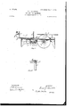
- Figure 1 is a plan view.
- Fig. 2 is a cross-section on line a a of Fig. 1.
- Fig. 3 is a cross-section on line 6 Z) of Fig. 1.
- Fig. 4 is a detail of the feed-cranks.
- A indicates the face, on which is journaled a shaft 1, provided with a pinion 2, that meshes with a driving master-wheel 3, actuated by a hand-crank 4.
- the shaft 1 carries a miter- Wheel 5, that meshes with a horizontal miterwheel 6 on the vertical shaft 7 of the horizontal saw 8.
- the upper surface of the shaft 7 is flush with the face of the saw 8, and the saw stands at an elevation above the table 9 at a distance equal to the thickness of the block of ice which is to be produced.
- a raised table-surface 10 on the same plane of the saw 8 is arranged to receive the block of ice that is passed over the saw and from the under side of which the finished blocks have been out.
- a carriage 19 travels across the table over the shaft 1 and between the members of the gang of saws. This is provided with a receptacle formed of the bottom part of the carriage and vertical sides 11 and 12, which are provided with passages for the saw.
- a rack 13 driven by feed-pawls 14 and 15, each of which is actuated by a crank on the shaft 16 of the master-wheel 3. The return movement of the carriage is effected manually, the operator grasping the handle 17, throwing the pawls 14: and 15 out of engagement by means of the rock-lever 18, and drawing the carriage-block.
- the particles of ice adhering to the horizontal saw 8 are blown from it by an air-blast produced in an air-pump c and conducted from the air-pump 0 through an air-conduit c.
- the air-pump c is secured to the framework and is actuated by an eccentric 22, that rotates in the opening of a cross-head 23 on the piston 2 1.
- a guard 21 covers the openings through the vertical wall 11 and protects the hands of the user from contact with the saws during the last part of the cut and when grasping the carriage for the return thereof.
- What I claim is 1.
- a gang of rotary saws mounted upon a horizontal shaft whose inner end carries a miter-wheel, a vertical shaft carrying a miterwhecl meshing therewith, a rotary saw mounted on the upper end thereof, a carriage adapted to move above the vertically-rotatable saws, a rack actuated by a pawl mounted on a shaft for moving the same, and means for driving the mechanism, substantially as described.
Landscapes
- Life Sciences & Earth Sciences (AREA)
- Forests & Forestry (AREA)
- Engineering & Computer Science (AREA)
- Mechanical Engineering (AREA)
- Sawing (AREA)
Description
No. 777,976. PATENTED DEC. 20, 1904. F. J, REINHOLD. 10B CUTTING MAGHINE.
APPLICATION FILED SEPT.16, 1903.
NO MODEL.
2 SHEETSSHEET l.
WITNESSES ZNVZWTOR 7%72 5w flitorneysQ No. 777,976. PATENTED DEC. 20, 1904.
F. J. REINHOLD.
ICE GUTTING' MACHINE.
APPLICATION FILED SEPT. 1a, 1903.
N0 MODEL. 2SEEETSSHEET 2.
WITNESSES I I IWVEWTOR 7%;7 g /6%. %fi g @y Patented December 20, 1904.
PATENT OFFICE.
FRANK J. REINHOLD, OF DETROIT, MICHIGAN.
ICE-CUTTING MACHINE.
SPECIFICATION forming part of Letters Patent No. 777,976, dated. December 20, 1904. Application filed September 16, 1903. $eria1No. 173,379.
To a. whom it may concern.-
Be it known that I, FRANK J. REINHOLD, a citizen of the United States, residing at Detroit, county of Wayne, State of Michigan, have invented a certain new and useful Improvement in Ice-Cutting Machines; and I declare the following to be a full, clear, and exact description of the invention, such as will enable others skilled in the art to which it pertains to make and use the same, reference being had to the accompanying drawings, which form a part of this specification.
This invention relates to ice-sawing machines, and has for its object an improved machine adapted and intended to produce small square blocks of ice from a larger cake.
In the drawings, Figure 1 is a plan view. Fig. 2 is a cross-section on line a a of Fig. 1. Fig. 3 is a cross-section on line 6 Z) of Fig. 1. Fig. 4 is a detail of the feed-cranks.
A indicates the face, on which is journaled a shaft 1, provided with a pinion 2, that meshes with a driving master-wheel 3, actuated by a hand-crank 4. The shaft 1 carries a miter- Wheel 5, that meshes with a horizontal miterwheel 6 on the vertical shaft 7 of the horizontal saw 8. The upper surface of the shaft 7 is flush with the face of the saw 8, and the saw stands at an elevation above the table 9 at a distance equal to the thickness of the block of ice which is to be produced. A raised table-surface 10 on the same plane of the saw 8 is arranged to receive the block of ice that is passed over the saw and from the under side of which the finished blocks have been out.
On the shaft 1 is a gang of saws of any proper number spaced to a distance equal to the thickness of the block of ice'that is to be produced. A carriage 19 travels across the table over the shaft 1 and between the members of the gang of saws. This is provided with a receptacle formed of the bottom part of the carriage and vertical sides 11 and 12, which are provided with passages for the saw. On the under side of the carriage is a rack 13, driven by feed-pawls 14 and 15, each of which is actuated by a crank on the shaft 16 of the master-wheel 3. The return movement of the carriage is effected manually, the operator grasping the handle 17, throwing the pawls 14: and 15 out of engagement by means of the rock-lever 18, and drawing the carriage-block.
The particles of ice adhering to the horizontal saw 8 are blown from it by an air-blast produced in an air-pump c and conducted from the air-pump 0 through an air-conduit c.
The air-pump c is secured to the framework and is actuated by an eccentric 22, that rotates in the opening of a cross-head 23 on the piston 2 1.
No carriage is used with the saw 8, as the block is pushed over it, and the severed blocks of ice fall through the opening 20. A guard 21 covers the openings through the vertical wall 11 and protects the hands of the user from contact with the saws during the last part of the cut and when grasping the carriage for the return thereof.
What I claim is 1. In an ice-sawing machine, the combination of a gang of rotary saws mounted upon a horizontal shaft whose inner end carries a miter-wheel, a vertical shaft carrying a miterwhecl meshing therewith, a rotary saw mounted on the upper end thereof, a carriage adapted to move above the vertically-rotatable saws, a rack actuated by a pawl mounted on a shaft for moving the same, and means for driving the mechanism, substantially as described.
2. In an ice-sawing machine, in combination with a plurality of rotary saws mounted upon a horizontal shaft and a miter-wheel mounted upon the inner end thereof, a vertical shaft carrying a miter-wheel meshing therewith, a rotary saw mounted on one end thereof, acarriage adapted to receive the block upon leaving the saw, and a feeding mechanism consisting of a rack driven by a pawl eccentrically mounted upon a shaft, and means for driving the mechanism, substantially as described.
3. In an ice-sawing machine, the combination of a vertical shaft, a horizontally-disposed rotary saw, and a miter-wheel mounted thereon with a horizontal shaft carrying a plurality of vertical saws and a miter-wheel on the end of said shaft intermeshing with the corre- In testimony whereof I sign this specification 1n the presence of two wltnesses.
FRANK J. REINHOLD.
Witnesses:
MAY E. KoTT, CHARLES F. BURTON.
Priority Applications (1)
| Application Number | Priority Date | Filing Date | Title |
|---|---|---|---|
| US1903173379 US777976A (en) | 1903-09-16 | 1903-09-16 | Ice-cutting machine. |
Applications Claiming Priority (1)
| Application Number | Priority Date | Filing Date | Title |
|---|---|---|---|
| US1903173379 US777976A (en) | 1903-09-16 | 1903-09-16 | Ice-cutting machine. |
Publications (1)
| Publication Number | Publication Date |
|---|---|
| US777976A true US777976A (en) | 1904-12-20 |
Family
ID=2846462
Family Applications (1)
| Application Number | Title | Priority Date | Filing Date |
|---|---|---|---|
| US1903173379 Expired - Lifetime US777976A (en) | 1903-09-16 | 1903-09-16 | Ice-cutting machine. |
Country Status (1)
| Country | Link |
|---|---|
| US (1) | US777976A (en) |
Cited By (1)
| Publication number | Priority date | Publication date | Assignee | Title |
|---|---|---|---|---|
| US4733437A (en) * | 1984-12-13 | 1988-03-29 | Heinz Nienstedt | Apparatus and method for cutting deep-frozen foodstuff |
-
1903
- 1903-09-16 US US1903173379 patent/US777976A/en not_active Expired - Lifetime
Cited By (1)
| Publication number | Priority date | Publication date | Assignee | Title |
|---|---|---|---|---|
| US4733437A (en) * | 1984-12-13 | 1988-03-29 | Heinz Nienstedt | Apparatus and method for cutting deep-frozen foodstuff |
Similar Documents
| Publication | Publication Date | Title |
|---|---|---|
| US254202A (en) | Circular sawing machine | |
| US409024A (en) | Machine for cutting curved surfaces | |
| US622048A (en) | Butter-forming machine | |
| US181862A (en) | Improvement in cracker-machines | |
| US346200A (en) | Feed-cutter | |
| US680051A (en) | Bread or candy dividing machine. | |
| US169700A (en) | Improvement in machines for making heads of wooden boxes | |
| US585789A (en) | rosback | |
| US514053A (en) | Machine for making moldings | |
| US1332A (en) | Jacob bentz | |
| US567734A (en) | Process of and apparatus for molding soap | |
| US584401A (en) | Oil cake teimmee | |
| US811336A (en) | Machine for cutting gear-wheels. | |
| US691432A (en) | Machine for cutting cork disks. | |
| US572232A (en) | Splint-machine | |
| US649860A (en) | Apparatus for cutting grooves in metal plates. | |
| US216461A (en) | Improvement in cake-machines | |
| US705543A (en) | Butter-cutter. | |
| US1072003A (en) | Bread-cutter. | |
| US293794A (en) | sebold | |
| US1218780A (en) | Block-finishing apparatus. | |
| US239230A (en) | Hollow brick and tile molding machine | |
| US552161A (en) | Machinery for cutting and sticking match-splints | |
| US619208A (en) | Stone-cutting machine | |
| US916104A (en) | Stone-cutting machine. |