US7792288B2 - Communication system using quantum cryptography and comprising switching stations - Google Patents
Communication system using quantum cryptography and comprising switching stations Download PDFInfo
- Publication number
- US7792288B2 US7792288B2 US10/535,363 US53536305A US7792288B2 US 7792288 B2 US7792288 B2 US 7792288B2 US 53536305 A US53536305 A US 53536305A US 7792288 B2 US7792288 B2 US 7792288B2
- Authority
- US
- United States
- Prior art keywords
- communication
- quantum
- switching
- stations
- station
- Prior art date
- Legal status (The legal status is an assumption and is not a legal conclusion. Google has not performed a legal analysis and makes no representation as to the accuracy of the status listed.)
- Active, expires
Links
- 238000004891 communication Methods 0.000 title claims abstract description 173
- 238000000034 method Methods 0.000 description 34
- 230000005540 biological transmission Effects 0.000 description 22
- 239000003999 initiator Substances 0.000 description 22
- 238000005259 measurement Methods 0.000 description 14
- 238000010586 diagram Methods 0.000 description 11
- 230000010287 polarization Effects 0.000 description 8
- 238000013475 authorization Methods 0.000 description 5
- 239000011152 fibreglass Substances 0.000 description 4
- 239000013078 crystal Substances 0.000 description 3
- 230000007246 mechanism Effects 0.000 description 3
- 238000012790 confirmation Methods 0.000 description 2
- 238000012937 correction Methods 0.000 description 2
- 230000010365 information processing Effects 0.000 description 2
- 230000000007 visual effect Effects 0.000 description 2
- OKUGPJPKMAEJOE-UHFFFAOYSA-N S-propyl dipropylcarbamothioate Chemical compound CCCSC(=O)N(CCC)CCC OKUGPJPKMAEJOE-UHFFFAOYSA-N 0.000 description 1
- 238000013459 approach Methods 0.000 description 1
- 230000009118 appropriate response Effects 0.000 description 1
- 230000001174 ascending effect Effects 0.000 description 1
- XBJJRSFLZVLCSE-UHFFFAOYSA-N barium(2+);diborate Chemical compound [Ba+2].[Ba+2].[Ba+2].[O-]B([O-])[O-].[O-]B([O-])[O-] XBJJRSFLZVLCSE-UHFFFAOYSA-N 0.000 description 1
- 238000001514 detection method Methods 0.000 description 1
- 230000000694 effects Effects 0.000 description 1
- 238000000605 extraction Methods 0.000 description 1
- 230000000977 initiatory effect Effects 0.000 description 1
- 239000013307 optical fiber Substances 0.000 description 1
- 230000008520 organization Effects 0.000 description 1
- 238000012545 processing Methods 0.000 description 1
- 238000009877 rendering Methods 0.000 description 1
- 238000012552 review Methods 0.000 description 1
- 239000013589 supplement Substances 0.000 description 1
- 238000012360 testing method Methods 0.000 description 1
Images




Classifications
-
- H—ELECTRICITY
- H04—ELECTRIC COMMUNICATION TECHNIQUE
- H04L—TRANSMISSION OF DIGITAL INFORMATION, e.g. TELEGRAPHIC COMMUNICATION
- H04L9/00—Cryptographic mechanisms or cryptographic arrangements for secret or secure communications; Network security protocols
- H04L9/08—Key distribution or management, e.g. generation, sharing or updating, of cryptographic keys or passwords
- H04L9/0816—Key establishment, i.e. cryptographic processes or cryptographic protocols whereby a shared secret becomes available to two or more parties, for subsequent use
- H04L9/0852—Quantum cryptography
- H04L9/0855—Quantum cryptography involving additional nodes, e.g. quantum relays, repeaters, intermediate nodes or remote nodes
Definitions
- the invention relates to a communication system using quantum cryptography, comprising subscriber stations which are connected to quantum channels and quantum-cryptographic devices which are associated with the quantum channels for generating a quantum key.
- Quantum cryptography employs quantum-physical effects so as to generate a more or less interception-safe key between communication partners, cf. e.g., N. Gisin, G. Ribordy, W. Tittel, H. Zbinden, “Quantum Cryptography”, Reviews of Modern Physics, Vol. 74, January 2002, pp. 145-195, or A. Karlsson et al., “Quantum Cryptography-From Single-Photon Transmission, Key Extraction Methods to Novel Quantum Information Protocols”, Evolutionary Computation, 1999; CEC 99; Proceedings of the 1999 Congress, Vol. 3, 6-9, July 1999, pp. 2247-2254.
- quantum cryptography photons containing quantum information are exchanged between two partners.
- the two partners measure certain properties of these photons, such as, e.g., the plane of polarization, obtain the same measurement results and therefore can construct an identical quantum key. In doing so, parts of the measurement results, such as, e.g., the exact points of time, are exchanged via public channels. In this manner, the two partners are capable of exactly associating the individual measurements to each other.
- two photons containing the same quantum information are generated simultaneously by a special technique.
- One photon each is sent to one of the two partners so that the two partners simultaneously will receive an identical measurement result and thus, each can construct the same quantum key for him/herself.
- the photons can be exchanged e.g. via a fiberglass connection, or also via a direct visual communication between two telescopes etc.
- Set-ups used so far have employed these fiberglass connections or direct visual connections for communication purposes employing the quantum cryptography described.
- the connections can be set up only over relatively short distances, e.g. only a few kilometers, for enabling the transmission of the photons, so that the use of the quantum cryptography so far has been restricted to partner stations of short distances only.
- the devices for the fiberglass connection or free space (line of sight) connection are also relatively expensive, and it would be desirable to be able to use known low-cost connections, in particular devices which already exist, for the encoded communication.
- the communication shall not be bound to certain cryptographic algorithms, and it shall be possible to supplement or replace, respectively, cryptographic algorithms in an existing system at any time.
- the communication system according to the invention and of the initially defined type is characterized in that several interconnected switching stations are provided to which the subscriber stations are connected via the quantum channels for generating a respective temporary quantum key.
- each switching station thus can have an associated zone in which associated subscriber stations are present which are connected to the associated switching station via comparatively short quantum channels (e.g. the previously mentioned fiberglass lines or free space connections with telescopes).
- the switching stations then are interconnected via conventional channels which are designed to be secure against eavesdropping in any manner known per se, such as by encryptions agreed upon.
- the subscriber stations can be equipped with relatively simple quantum-cryptographic devices, whereas the complex devices can be concentrated in the switching stations. Accordingly, it is advantageous if the switching stations contain a source of photons as quantum-cryptographic device as well as also a photon detector, in case interlaced photons are used. On the other hand, the subscriber stations may merely contain a photon detection device. Thus, the photon source will only be present at the switching stations, and at the subscriber stations the technical means for detecting the photons will suffice.
- the switching stations can be interconnected in a manner known per se in switching technique, at least partially in the form of point-to-point links, or also in the form of a hierarchy.
- the quantum channels need only be used in the course of generating the quantum keys, and as soon as the quantum keys have been generated, the communication partners can also communicate with each other in a conventional manner. Accordingly, it is suitable if the subscriber stations communicate via public lines, using the quantum key generated via the switching stations. In this manner, the quantum lines, or quantum channels, respectively, which as such are very expensive, are kept free and utilized for the quantum key generation only, and for the subsequent communication, using the quantum keys, conventional lines, or channels, respectively, can be used, such as telephone lines, radio links or the like links.
- a preferred embodiment of the communication system provides for the subscriber stations engaged in the desired communication to generate a separate—respective first or second—key bit sequence with their associated switching station via the quantum channel after a request for a communication has been transmitted via the respective switching station.
- the switching station associated with the called subscriber station generates a third key bit sequence from the key bit sequences generated via the quantum channels, and transmits this third key bit sequence to the called subscriber station which, using its known second key bit sequence generated by it with the associated switching station, from the third key bit sequence generates the—on the side of the calling subscriber station—first—key bit sequence which then finally is used as a mutual key for the communication between the subscriber stations.
- the quantum key generated is checked for its freedom from interference, and if, as a consequence of a possible interference detected which is associated with an eavesdropping, the established communication is disrupted and the key is discarded.
- the stationarily set-up switching stations can communicate with each other via conventional, in particular public lines, using the encryption agreed upon.
- FIG. 1 schematically shows the set-up of an inventive system with switching stations and respective associated subscriber stations
- FIG. 2 shows a hierarchical model for interconnecting the individual switching stations
- FIG. 3 shows a node-to-node model for connecting the switching stations, as an alternative to FIG. 2 ;
- FIG. 4 schematically shows the essential quantum cryptographic devices in a switching station and in a subscriber station, respectively, in a type of block diagram, here for the instance of producing interlaced photons;
- FIG. 5A shows a diagram for illustrating the sequence in case of a request for setting up a communication through a subscriber station, a resource-oriented set-up being made here;
- FIG. 5B shows a diagram for the sequence in case of a request for a speed-oriented communication set-up, as an alternative to FIG. 5A ;
- FIG. 6 shows a diagram for illustrating the set-up of the secure communication in case of the communication requirements according to FIGS. 5A and 5B , respectively;
- FIGS. 7A and 7B show in a manner corresponding to FIGS. 5A and 5B the situation in which the requesting subscriber station and the requested subscriber station are associated to one and the same switching station, and this once more for the case of the resource-oriented communication set up ( FIG. 7A ) and for the case of the speed-oriented communication set-up ( FIG. 7B ), respectively;
- FIG. 8 shows a diagram pertaining to FIGS. 7A and 7B for illustrating the set-up of the secure communication between the two subscriber stations which here are connected to one and the same switching station;
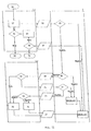
- FIG. 9 shows a flow chart for illustrating the steps at a request for a communication set-up including two switching stations
- FIG. 10 shows an associated flow chart for illustrating the set-up of the secure communication therefor
- FIG. 11 shows a flow chart for illustrating the procedures at a request for a communication set-up if only one switching station is involved;
- FIG. 12 shows the flow chart associated to FIG. 11 for illustrating the set-up of the secure communication, if only one switching station is involved.
- FIG. 13 shows a flow chart for illustrating the generation of a key bit sequence between a subscriber station and a switching station.
- a communication system including fixed switching stations 1 , 2 . . . is shown schematically, wherein one or more subscriber stations are connected to each switching station 1 , 2 , e.g. the subscriber stations 1 . 1 , 1 . 2 , . . . , 1 . i . . . , 1 . m are connected to the switching station 1 , and the subscriber stations 2 . 1 , 2 . 2 , . . . , 2 . i , . . . , 2 . n are connected to the switching station 2 , via quantum channels 3 .
- the subscriber stations 1 . i , 2 . i , . . . are interconnected via public lines 4 .
- the switching stations 1 , 2 . . . may be interconnected in various ways, as will be explained in more detail hereinafter by way of FIGS. 2 and 3 .
- the switching stations 1 , 2 have the function of generating the secure quantum key together with the subscriber stations 1 . i , 2 .
- the switching stations 1 , 2 . . . are interconnected via public lines, dedicated lines or the like channels 5 , an encryption, however, being provided for the communication between the switching stations 1 , 2 to thus make the information exchange during the key generation secure also from this side.
- the switching stations 1 , 2 form “points of trust”, wherein the switching stations 1 , 2 communicating with each other—depending on the architecture—must have exchanged a key.
- the set-up of the network with the switching stations 1 , 2 can be provided in different, per se conventional, ways, two possibilities being illustrated as examples in FIGS. 2 and 3 .
- FIG. 2 a hierarchical model is shown, wherein the connection between the two switching stations 1 , 2 (cf. also FIG. 1 ) is effected via a hierarchical structure, at first ascending, then descending again, via switching stations 6 , 7 , 8 , 9 .
- each of the switching stations 1 , 2 , 6 ′, 7 ′ shown there can directly communicate with each other, i.e. this is a so-called point-to-point model.
- the concrete way of the connection between the switching stations 1 , 2 is of no further relevance for the function of the present communication system using quantum cryptography. It is only essential that for providing a secure, quantum cryptographically encoded communication between subscriber stations 1 . i , 2 .
- the switching stations 1 , 2 are involved, with these switching stations 1 , 2 being interconnected in a secure way so that the key bit sequences (so-called streams), required for generating the key on the side of both subscriber stations involved in a communication, can be exchanged via the quantum channels 3 which, due to the technical circumstances necessarily are short, and via the switching stations 1 , 2 etc.; with a view to this, the subscriber stations 1 . i , 2 . i may also be provided at arbitrary, large distances from each other. With this, a communication employing quantum cryptography is enabled between subscriber stations 1 . i , 2 . i very far from each other, i.e. without being restricted to the short distances as hitherto required by the quantum channels 3 given by optical fiber lines or by line of sight connections realized by means of a telescope.
- quantum cryptography Due to the particular “randomness” of certain properties of photons used therein, quantum cryptography is highly secure.
- photons comprising quantum information are exchanged between two partners. Both partners measure certain properties of these photons (e.g. the plane of polarization), obtain the same measurement results, and therefore are able to build up an identical key. In doing so, parts of the measurement results—e.g., the exact points of time—are exchanged via public channels. By this, both partners are able to exactly associate the individual measurements.
- a partner generates a sequence of single photons which he sends through a polarizer whose plane of polarization is randomly varied. The setting of the polarizer is transmitted. If a photon is registered by the other partner, its plane of polarization thus is clearly determined. It must, however, be ensured that in fact only a single photon is generated, because in case of several photons of the same polarization, one of the photons could be intercepted by a third party.
- Interlaced photons (so-called “qubits”): By special methods, two photons are produced simultaneously which contain the same quantum information. Each photon is sent to one of the two partners so that the partners simultaneously receive the identical measurement result and thus can build up an identical key.
- photons are exchanged between the two communication partners. These photons are derived from a source which—depending on the method chosen, is either directly arranged at one of the two communication partners (single photon method) or between the two partners (interlaced photons).
- the source of photons is only installed at one of the two communication partners, i.e. in particular at the switching station, e.g. 1 .
- the switching station 1 both the source of photons and when using qubits—also a photon detector is present.
- the subscriber station e.g. 1 . i , then merely the technical prerequisites for detecting the photons are necessary.
- the switching station 1 is shown by way of example, which, as has been mentioned, is connected with associated subscriber stations, in particular the subscriber station 1 . i , via a quantum channel 3 , a source of photon pairs 10 being provided in the switching station 1 . Via an internal quantum line 3 ′, this photon pair source 10 is further connected to a photon detector 11 within the switching station 1 ; a correspondingly designed detector 11 ′ is present in the subscriber station 1 . i , and subsequently always one detector, 11 e.g., will be explained with reference to components 12 to 18 which have the same reference numbers for both detectors 11 , 11 ′.
- the detector, 11 e.g., comprises an active polarizer 12 on its input side, to which an appropriate adjustment signal is supplied via a control unit 13 . Then the photon gets to a polarizing beam divider 14 which is followed by two avalanche photodiodes 15 , 16 to the outputs of which an analyzing unit 17 , e.g. a time interval analyzer, is connected. Besides, the further common communications control units are comprised together with a circuit module 18 .
- the photon pair source 10 may be set up in conventional manner with a pump beam laser, the pump beam being supplied to a non-linear crystal, e.g. a barium borate crystal (“BBO crystal”), the interlaced photons or “qubits” being produced by this laser irradiation.
- a non-linear crystal e.g. a barium borate crystal (“BBO crystal”)
- BBO crystal barium borate crystal
- a request for establishing the communication is made, wherein one subscriber station, e.g. 1 . 1 , triggers this phase by a respective request; subsequently, a secure communication is established, and finally, the actual communication by using the quantum key generated.
- FIG. 5A a diagram is shown to illustrate the procedures when requesting the establishment of a communication, this being based on a resource-oriented set-up, in detail.
- a speed-oriented set-up as will be explained hereinafter by way of FIG. 5B
- all the partial steps are started by the “calling” subscriber station, e.g. 1 . 1 , so that more communication steps have to be carried out than with the speed-oriented set-up.
- the partner i.e. of the called subscriber station, e.g. 2 . 1
- the partner i.e. of the called subscriber station, e.g. 2 . 1
- subscriber hereinafter, and that subscriber station from which a request emanates, is also termed “initiator” or “party calling subscriber”, whereas the called subscriber station will be termed “target station”.
- the subscriber station 1 . 1 associated with the switching station 1 desires a communication with the subscriber station 2 . 1 associated with the switching station 2 .
- the designation of the subscriber stations and switching stations is to be understood without restricting its generality.
- the vertical blocks generally indicate communication steps (in FIG. 5A , communication steps 21 to 28 ), and the horizontal arrows between the individual stations 1 . 1 , 1 , 2 , 2 . 1 indicate data transmissions (in FIG. 5A , data transmissions 31 to 38 ).
- the calling subscriber 1 . 1 according to block 21 first sends a request to its associated switching station 1 , the data transmission according to arrow 31 containing his identification as well as the desired partner (target station 2 . 1 ).
- the switching station 1 checks the data received from initiator 1 . 1 (e.g.
- the data transmitted according to arrow 32 mainly indicate the desired subscriber 2 . 1 as well as also the calling subscriber 1 . 1 .
- the switching station 2 requests its associated called subscriber 2 . 1 to communicate, transmitting a request for identification according to arrow 33 , to which the called subscriber 2 . 1 responds according to block 24 and by transmitting his data back to the switching station 2 according to arrow 34 .
- the switching station 2 checks the data of the called subscriber 2 . 1 (regarding authentication, authorization, account information etc.) and, if the result of the check is positive, it transmits the respective information regarding the desired communication to the called subscriber 2 . 1 , cf. request arrow 35 in FIG. 5A . This information particularly contains data relating to the calling subscriber 1 . 1 .
- the called subscriber 2 .
- the switching station 1 then positively confirms the request, and according to arrow 36 , as an answer, he returns this confirmation, including a request to communicate, to the switching station 2 which in turn—cf. block 27 —transmits the answer to the switching station 1 , cf. also arrow 37 ; according to block 28 , the switching station 1 then transmits this answer to the calling subscriber 1 . 1 . cf. also the data transmission according to arrow 38 .
- the answer of the target station 2 . 1 is not directly returned to the initiator 1 . 1 , much rather the target station 2 . 1 , answering to the request, takes up the active role in the establishment of the secure communication, wherein the number of the individual steps required can be reduced and the communication establishment can be accelerated.
- the set-up of the secure communication is schematically illustrated in FIG. 6 , this set-up being respectively true for both aforementioned variants (resource-oriented and speed-oriented communication set-up).
- the request for a communication establishment is schematically illustrated in FIG. 6 by the continuous arrow 40 .
- Blocks 41 to 47 then again denote the communications steps which will be explained in more detail hereinafter, and the arrows and double arrows 48 to 52 denote the concrete data transmissions, i.e. particularly the transmissions of key bit sequences (“streams”).
- the calling subscriber 1 . 1 is ready to communicate, and together with the switching station 1 , he generates the first key bit sequence 48 (stream 1 ) via the associated quantum line 3 (cf. FIG. 1 ), cf. also block 42 which illustrates the key bit sequence generation on the side of the switching station 1 .
- the first key bit sequence 48 is generated on the basis of quantum mechanisms, as has been described.
- a second key bit sequence (double arrow 49 ), a so-called stream 2 , is likewise generated between the other switching station 2 and the called subscriber 2 . 1 on the basis of quantum mechanisms and via the quantum line 3 provided there.
- the first switching station 1 by means of a method agreed upon between the switching stations 1 , 2 , encodes the first key bit sequence and transmits it in encoded form to the second switching station 2 , cf. also arrow 50 , which illustrates this transmission of the encoded first key bit sequence.
- the second switching station 2 From the encoded first bit sequence as well as from the second key bit sequence (double arrow 49 ), according to block 46 , the second switching station 2 then generates a third key bit sequence (stream 3 ) which, according to arrow 51 , is transmitted to the called subscriber 2 . 1 . From the received third bit sequence 51 and the second key bit sequence already known to him (cf. arrow 49 ), the called subscriber 2 .
- this first key bit sequence then is used as key, as so-called “session key”, for the further communication together with the calling subscriber 1 . 1 .
- FIGS. 7A and 7B then illustrate the special case that both subscriber stations, i.e. the calling subscriber station 1 . 1 . just like the called subscriber station 1 . 2 , are associated to one and the same switching station 1 .
- subscriber stations i.e. the calling subscriber station 1 . 1 . just like the called subscriber station 1 . 2
- FIG. 8 the set-up of the secure communication equally applicable to both cases is illustrated. Since, as has been mentioned, these are special cases of the diagrams according to FIGS. 5A , 5 B and 6 , corresponding reference numbers have again been used in FIGS.
- FIG. 7A , 7 B and 8 for the corresponding communication steps and data transmissions, and, as far as they correspond to each other, a repeated description of these communications steps and data transmissions is not required.
- FIG. 7A when comparing FIG. 7A with FIG. 5A , it appears that the two switching stations 1 and 2 according to FIG. 5A are to be combined to just one switching station 1 , the data transmissions 32 and 37 being omitted and the communication steps 22 , 23 on the one hand, and 27 , 28 , on the other hand, coinciding.
- the switching station 1 checks—block 53 —the data of the calling subscriber 1 . 1 (authentication, authorization, account information etc.) and requests the called subscriber 1 .
- the switching station 1 after having received the confirmation and the request to communicate on the part of the called subscriber station 1 . 2 (cf. arrow 36 ′), transmits this answer directly to the called subscriber 1 . 1 , cf. arrow 38 .
- FIGS. 9 and 10 the mode of procedure used at a request for establishing a communication, and when establishing the secure communication, namely when incorporating two switching stations ( FIGS. 9 and 10 ), and in case the two subscriber stations are associated to one and the same switching station ( FIGS. 11 and 12 ), shall be explained in more detail by way of example.
- the subscriber stations are always associated to certain switching stations, and a quantum key is generated between one switching station each and a subscriber station. Normally, different switching stations will participate in the establishment of the communication and in the generation of the key, respectively, these switching stations in turn being interconnected either directly or via any network structure desired.
- the subscribers involved in the communication to be established are associated to one and the same switching station, i.e. arranged in one and the same “trust zone”.
- a request for communication is made by assembling the required data and preparing them in the form of a data package.
- a request for communication may, e.g., have the following contents:
- this request is transmitted to the pertinent switching station, e.g. 1 , via a public line.
- Incoming requests are checked by the respective switching station, i.e. here switching station 1 .
- the data of the initiator 1 . 1 are checked, cf. block 59 .
- Such a check could comprise the checking of various information, such as, e.g., the authentication of the initiator, the authorization of the initiator to communicate (with the target station, with this confidentiality level, at this point of time etc.), accounting information etc.
- block 60 a negative result of this check will lead to the discontinuation of the communication and to the generation of an appropriate response according to block 61 , this response—according to block 62 —being returned to the initiator 1 . 1 .
- the information regarding the target station 2 . 1 will be checked.
- the check could regard information like the following, for instance: availability of the target station, permission of the communication with the initiator, accounting information of the target station, confidentiality level of the communication, etc. If the check yields a negative result, the communication will be discontinued again (block 60 ), and a respective report will be transmitted to the initiator (blocks 61 , 62 ).
- This switching station 2 can be reached in various ways. Examples of this would be a hierarchical organization of the individual switching stations (cf. FIG. 2 ), or via a direct connection between all the switching stations (cf. FIG. 3 ).
- the request is received and processed by the switching station 2 associated with the target station 2 . 1 .
- the data of the target station 2 . 1 are checked, cf. block 65 , wherein, e.g., the accounting information of the target station 2 . 1 is checked, since this information may possibly only be known to the responsible switching station 2 .
- information regarding the degree of confidentiality or the circle of the allowed communication partners could be known to the responsible switching station 2 only, and therefore be checked only in this step, block 65 .
- a negative result of the check will lead to a discontinuation of the communication, block 66 , and to a respective report, cf. block 67 , which, according to block 68 , will be returned to the first switching station.
- the target station 2 . 1 may be requested by the responsible switching station 2 for an authentication.
- the target station 2 . 1 would be informed about the request for a communication.
- all information of the request could be transmitted, yet optionally they could also be transmitted only after a successful identification, as illustrated in FIG. 9 .
- the data required for the communication will be transmitted to the target station 2 . 1 only after a positive check of the identity so as to ensure a higher degree of security.
- the identification data (according to block 71 ) are returned to the associated switching station 2 , where they are checked according to block 72 .
- the request according to block 73 will be transmitted to the target station 2 . 1 , whereupon the latter, according to block 74 , can agree to the establishment of a communication or reject the same.
- the reply of the target station 2 . 1 is transmitted to the initiator 1 . 1 as well as to all the switching stations 2 , 1 involved, e.g. blocks 75 , 76 as well as block 77 .
- the respective initializations can be prepared—in case of a positive reply, block 75 .
- the respective reply will be checked at the initiator, i.e. at the calling subscriber 1 . 1 , according to block 78 , and in a positive case, according to field 79 the readiness for a communication prevails.
- the initiator 1 . 1 can again begin to establish a communication, cf. request 81 in FIG. 9 .
- the parameters such as, e.g., the maximum number of communication attempts per time unit, costs per communication attempt etc., may be used for controlling purposes. If the decision at the request 81 is negative, according to field 82 the communication attempt will finally be discontinued.
- the initiator 1 . 1 of the communication Together with his switching station 1 , the initiator 1 . 1 of the communication generates a “stream 1 ” with agreed-upon quality criteria and a corresponding key length.
- a key length of 256 bits is agreed upon.
- FIG. 10 following a start step 83 , this is illustrated by the blocks 84 (initiation of the stream 1 -generation) and 85 (stream 1 -generation).
- the status of the generation (cf. block 86 ) is checked (block 87 ). A negative status will lead to a discontinuation of the communication, cf. field 88 .
- the generated stream 1 will be encoded—according to block 89 —by the switching station 1 of the initiator 1 . 1 .
- Encoding of the stream 1 may, e.g., be effected by symmetrical methods, such as AES, or by asymmetrical methods.
- the switching station 2 of the target station 2 . 1 After having received the encoded stream 1 (cf block 90 ), the switching station 2 of the target station 2 . 1 according to block 91 initiates the generation of the second key bit sequence (stream 2 ) with the target station 2 . 1 , cf. block 92 . Also here, respective quality criteria could be agreed upon, the length, e.g., could correspond to the length of stream 1 , depending on the method chosen later on. Subsequently, the status (cf. block 93 ) is checked (block 94 ). In case of a negative status, the communication is discontinued, cf. field 95 .
- the encoded stream 1 will be decoded in the next step (block 96 ), and subsequently encoded with the generated stream 2 to give the third key bit sequence—stream 3 , cf. block 97 .
- An example of an encryption would be the transmissionless addition (XOR operation) of the two streams 1 and 2 . For this purpose, it is necessary that both streams 1 and 2 have the same lengths and meet quality criteria defined beforehand.
- the stream 3 generated in this manner is transferred to the target station 2 . 1 and is decoded again there with the stream 2 , cf. block 99 .
- the result of decoding (stream 1 ) will be termed “session key” hereinafter, and according to block 100 it is used as key when establishing the connection.
- the target station 2 . 1 now starts the connection establishment with the initiator 1 . 1 , cf. block 100 , and the latter takes up the communication, cf. block 101 .
- the connection established is checked, cf. block 102 . If this check of the communication yields a negative result, the communication is discontinued, at a positive result, the communication is secure as defined by this method, cf. (field 103 ) field 104 , and the communication can occur, using the session key (stream 1 ).
- the system provider may define the further procedure in case of a discontinuation, repeating, e.g., unsuccessful steps. Whether or not a repetition is possible could also depend on the conditions of the communication set-up agreed upon in the first step; for this, also the point of time of the beginning of the communication agreed upon could be relevant.
- FIGS. 11 and 12 again relate to the instance in which the called subscriber station, here 1 . 2 , is associated to the same switching station 1 as the calling subscriber station 1 . 1 .
- FIG. 11 When looking at the individual steps in the sequence regarding the request to communicate (cf. FIG. 11 as compared to FIG. 9 ), it can be seen that different steps regarding the data transmission between the switching stations 1 and 2 can be omitted in FIG. 11 in comparison with FIG. 9 , such as particularly the blocks 59 ′, 63 , 64 and 68 of FIG. 9 . Checking of the data of the target station 1 . 2 is effected only once, cf.
- block 65 just as a discontinuation of the communication also is provided for only once—according to block 105 , i.e. block 105 in FIG. 11 corresponds to the combination of blocks 60 and 66 in FIG. 9 ; similar facts hold for the provision of the respective reply according to block 106 in FIG. 11 which corresponds to the combination of the blocks 61 and 67 in FIG. 9 . Otherwise, the sequence is the same as in FIG. 9 so that no further explanations of FIG. 11 are required in order to avoid repetitions.
- the procedure when generating a key bit sequence, a “stream”, shall be explained in more detail.
- the initiator i.e. the calling subscriber station, i.e. subscriber 1 . 1 e.g., at the beginning of the generation makes a corresponding request, cf. block 108 in FIG. 13 .
- This request may contain different tokens, such as, e.g., the length of the stream to be generated, the quality criteria of the stream, such as, e.g., FIPS 140-2 (cf. “Security Requirements for Cryptographic Modules”, Federal Information Processing Standards Publication, pp. 140-2, NIST), criteria according to Golomb (cf. A.
- the request is transmitted to both communication partners involved and serves to initiate appropriate steps, such as preparing the system (adjusting, self-test, etc.), recording etc.
- Bennett and Brassard cf. C. H. Bennett, F. Bessette, G. Brassard, L. Salvail, J. Smolin, “Experimental Quantum Cryptography”, J. Cryptology (1992) 5; pp. 3-28.
- the quality criteria previously defined in the request can be checked. If the generated stream is denied within the scope of the check, a respective error report is generated (block 113 ) and sent to the second communication partner—here the initiator 1 . 1 —cf. block 114 .
- a positive status report is generated according to block 115 .
- the latter confirms that both communication partners now have a key which they have generated together.
- an error report it may be open to the initiator to start a further attempt at generating a key, cf. block 116 .
- the system provider could intervene in a controlling manner, e.g. by allowing only a certain number of attempts per time unit, by billing each attempt individually etc. If the attempt is not repeated, a negative status report is generated according to block 117 , confirming that a common key could not be generated.
- the final status is illustrated by block 118 in FIG. 13 and determines the further course (encoded communication, or discontinuation).
Landscapes
- Engineering & Computer Science (AREA)
- Physics & Mathematics (AREA)
- Electromagnetism (AREA)
- Theoretical Computer Science (AREA)
- Computer Security & Cryptography (AREA)
- Computer Networks & Wireless Communication (AREA)
- Signal Processing (AREA)
- Optical Communication System (AREA)
- Radio Relay Systems (AREA)
- Data Exchanges In Wide-Area Networks (AREA)
- Circuits Of Receivers In General (AREA)
Applications Claiming Priority (3)
| Application Number | Priority Date | Filing Date | Title |
|---|---|---|---|
| AT0175502A AT412932B (de) | 2002-11-22 | 2002-11-22 | Kommunikationssystem mit quantenkryptographie |
| ATA1755/2002 | 2002-11-22 | ||
| PCT/AT2003/000351 WO2004049623A1 (de) | 2002-11-22 | 2003-11-21 | Kommunikationssystem mit quantenkryptographie und vermittlungsstationen |
Publications (2)
| Publication Number | Publication Date |
|---|---|
| US20060013396A1 US20060013396A1 (en) | 2006-01-19 |
| US7792288B2 true US7792288B2 (en) | 2010-09-07 |
Family
ID=32330376
Family Applications (1)
| Application Number | Title | Priority Date | Filing Date |
|---|---|---|---|
| US10/535,363 Active 2027-10-07 US7792288B2 (en) | 2002-11-22 | 2003-11-21 | Communication system using quantum cryptography and comprising switching stations |
Country Status (7)
| Country | Link |
|---|---|
| US (1) | US7792288B2 (de) |
| EP (1) | EP1563638B1 (de) |
| JP (1) | JP4610342B2 (de) |
| AT (2) | AT412932B (de) |
| AU (1) | AU2003285968A1 (de) |
| DE (1) | DE50303741D1 (de) |
| WO (1) | WO2004049623A1 (de) |
Cited By (5)
| Publication number | Priority date | Publication date | Assignee | Title |
|---|---|---|---|---|
| US20140119537A1 (en) * | 2010-10-08 | 2014-05-01 | Matthieu Legre | Apparatus and method for the detection of attacks taking control of the single photon detectors of a quantum cryptography apparatus by randomly changing their efficiency |
| US11411722B2 (en) | 2019-05-03 | 2022-08-09 | Quantumxchange, Inc. | Method of operation of a quantum key controller |
| US11424918B2 (en) | 2019-05-03 | 2022-08-23 | Quantumxchange, Inc. | Method of operation of a trusted node software in a quantum key distribution system |
| US11469888B2 (en) | 2019-05-03 | 2022-10-11 | Quantumxchange, Inc. | Tamper detection in a quantum communications system |
| US11483140B2 (en) | 2019-08-02 | 2022-10-25 | Quantumxchange, Inc. | Secure out-of-band symmetric encryption key delivery |
Families Citing this family (19)
| Publication number | Priority date | Publication date | Assignee | Title |
|---|---|---|---|---|
| US20050286723A1 (en) * | 2004-06-28 | 2005-12-29 | Magiq Technologies, Inc. | QKD system network |
| WO2006014298A2 (en) * | 2004-07-02 | 2006-02-09 | Magiq Technologies, Inc. | Qkd cascaded network with loop-back capability |
| US7826749B2 (en) * | 2005-09-19 | 2010-11-02 | The Chinese University Of Hong Kong | Method and system for quantum key distribution over multi-user WDM network with wavelength routing |
| US7889868B2 (en) | 2005-09-30 | 2011-02-15 | Verizon Business Global Llc | Quantum key distribution system |
| JP4622866B2 (ja) * | 2006-01-16 | 2011-02-02 | 日本電気株式会社 | 量子暗号通信システム及びそれに用いる量子暗号鍵配布方法、通信装置並びにそれに用いる暗号通信方法 |
| AT503669B1 (de) | 2006-07-03 | 2007-12-15 | Arc Austrian Res Centers Gmbh | Knoteneinrichtung für ein netzwerk mit quantenkryptographischen verbindungen sowie knotenmodul für eine derartige knoteneinrichtung |
| WO2009060283A1 (en) * | 2007-11-05 | 2009-05-14 | Synaptic Laboratories Limited | Method and apparatus for secure communication |
| GB0801395D0 (en) * | 2008-01-25 | 2008-03-05 | Qinetiq Ltd | Network having quantum key distribution |
| WO2010013121A2 (en) * | 2008-07-28 | 2010-02-04 | Synaptic Laboratories Ltd. | Method and apparatus for initialising a cryptographic communications system |
| KR101621266B1 (ko) * | 2010-09-10 | 2016-05-16 | 삼성전자주식회사 | 단일 블루투스 채널을 이용한 블루투스 기기간 연결 방법 및 상기 방법을 이용하는 블루투스 기기 |
| GB201020424D0 (en) | 2010-12-02 | 2011-01-19 | Qinetiq Ltd | Quantum key distribution |
| GB2492083B8 (en) * | 2011-06-17 | 2016-02-10 | Toshiba Res Europ Ltd | A quantum communication network |
| JP6359285B2 (ja) * | 2014-02-17 | 2018-07-18 | 株式会社東芝 | 量子鍵配送装置、量子鍵配送システムおよび量子鍵配送方法 |
| CN105827397B (zh) | 2015-01-08 | 2019-10-18 | 阿里巴巴集团控股有限公司 | 基于可信中继的量子密钥分发系统、方法及装置 |
| US11711210B2 (en) | 2020-12-28 | 2023-07-25 | Mellanox Technologies, Ltd. | Quantum key distribution-based key exchange orchestration service |
| US11895233B2 (en) * | 2020-12-28 | 2024-02-06 | Mellanox Technologies, Ltd. | Quantum key distribution enabled intra-datacenter network |
| EP4123957B1 (de) * | 2021-07-19 | 2025-05-14 | Adva Network Security GmbH | Verfahren und system zur durchführung eines sicheren schlüsselrelais eines verschlüsselungsschlüssels |
| JP7837537B2 (ja) * | 2021-12-23 | 2026-03-31 | 国立研究開発法人情報通信研究機構 | 暗号鍵共有システム |
| IL298938A (en) | 2022-12-08 | 2024-07-01 | Mellanox Technologies Ltd | Measurement-based methods for accessing and characterizing quantum communication channels |
Citations (10)
| Publication number | Priority date | Publication date | Assignee | Title |
|---|---|---|---|---|
| US5142578A (en) * | 1991-08-22 | 1992-08-25 | International Business Machines Corporation | Hybrid public key algorithm/data encryption algorithm key distribution method based on control vectors |
| US5850441A (en) * | 1993-09-09 | 1998-12-15 | British Telecommunications Public Limited Company | System and method for key distribution using quantum cryptography |
| US20010055389A1 (en) * | 2000-04-28 | 2001-12-27 | Hughes Richard J. | Method and apparatus for free-space quantum key distribution in daylight |
| US20030002674A1 (en) * | 2001-06-29 | 2003-01-02 | Nec Corporation | Quantum cryptography multi-node network system |
| US20040005061A1 (en) * | 2002-07-08 | 2004-01-08 | Buer Mark L. | Key management system and method |
| US6895091B1 (en) * | 2000-07-07 | 2005-05-17 | Verizon Corporate Services Group Inc. | Systems and methods for encryption key archival and auditing in a quantum-cryptographic communications network |
| US7068790B1 (en) * | 2001-08-31 | 2006-06-27 | Bbn Technologies Corp. | Systems and methods for path set-up in a quantum key distribution network |
| US20070140495A1 (en) * | 2003-11-13 | 2007-06-21 | Magiq Technologies, Inc | Qkd with classical bit encryption |
| US7324647B1 (en) * | 2000-10-23 | 2008-01-29 | Bbn Technologies Corp. | Quantum cryptographic key distribution networks with untrusted switches |
| US7457416B1 (en) * | 2002-07-17 | 2008-11-25 | Bbn Technologies Corp. | Key distribution center for quantum cryptographic key distribution networks |
Family Cites Families (1)
| Publication number | Priority date | Publication date | Assignee | Title |
|---|---|---|---|---|
| AU2001273267A1 (en) * | 2000-07-07 | 2002-01-21 | Bbnt Solutions Llc | Systems and methods for implementing a quantum-cryptographic communications network |
-
2002
- 2002-11-22 AT AT0175502A patent/AT412932B/de not_active IP Right Cessation
-
2003
- 2003-11-21 DE DE50303741T patent/DE50303741D1/de not_active Expired - Lifetime
- 2003-11-21 AT AT03776641T patent/ATE329425T1/de not_active IP Right Cessation
- 2003-11-21 WO PCT/AT2003/000351 patent/WO2004049623A1/de not_active Ceased
- 2003-11-21 JP JP2004554038A patent/JP4610342B2/ja not_active Expired - Fee Related
- 2003-11-21 AU AU2003285968A patent/AU2003285968A1/en not_active Abandoned
- 2003-11-21 EP EP03776641A patent/EP1563638B1/de not_active Expired - Lifetime
- 2003-11-21 US US10/535,363 patent/US7792288B2/en active Active
Patent Citations (10)
| Publication number | Priority date | Publication date | Assignee | Title |
|---|---|---|---|---|
| US5142578A (en) * | 1991-08-22 | 1992-08-25 | International Business Machines Corporation | Hybrid public key algorithm/data encryption algorithm key distribution method based on control vectors |
| US5850441A (en) * | 1993-09-09 | 1998-12-15 | British Telecommunications Public Limited Company | System and method for key distribution using quantum cryptography |
| US20010055389A1 (en) * | 2000-04-28 | 2001-12-27 | Hughes Richard J. | Method and apparatus for free-space quantum key distribution in daylight |
| US6895091B1 (en) * | 2000-07-07 | 2005-05-17 | Verizon Corporate Services Group Inc. | Systems and methods for encryption key archival and auditing in a quantum-cryptographic communications network |
| US7324647B1 (en) * | 2000-10-23 | 2008-01-29 | Bbn Technologies Corp. | Quantum cryptographic key distribution networks with untrusted switches |
| US20030002674A1 (en) * | 2001-06-29 | 2003-01-02 | Nec Corporation | Quantum cryptography multi-node network system |
| US7068790B1 (en) * | 2001-08-31 | 2006-06-27 | Bbn Technologies Corp. | Systems and methods for path set-up in a quantum key distribution network |
| US20040005061A1 (en) * | 2002-07-08 | 2004-01-08 | Buer Mark L. | Key management system and method |
| US7457416B1 (en) * | 2002-07-17 | 2008-11-25 | Bbn Technologies Corp. | Key distribution center for quantum cryptographic key distribution networks |
| US20070140495A1 (en) * | 2003-11-13 | 2007-06-21 | Magiq Technologies, Inc | Qkd with classical bit encryption |
Non-Patent Citations (4)
| Title |
|---|
| Elliott, "Building the quantum network," New Journal of Physics, 4:46.1-46.12, 2002. |
| Gisin et al., "Quantum cryptography," Rev. Of Mod. Physics, 741-50, 2002. |
| Karlsson et al., "Quantum Cryptography-from single-photon transmission, key extraction methods to novel quantum information protocols," Evolutionary Computation, CEC99, Proceedings fo the 1999 Congress, 3: 2247-2254, 1999. |
| Menezes, Alfred et al. "Handbook of Applied Cryptography", CRC press 1997, p. 553. * |
Cited By (6)
| Publication number | Priority date | Publication date | Assignee | Title |
|---|---|---|---|---|
| US20140119537A1 (en) * | 2010-10-08 | 2014-05-01 | Matthieu Legre | Apparatus and method for the detection of attacks taking control of the single photon detectors of a quantum cryptography apparatus by randomly changing their efficiency |
| US9634835B2 (en) * | 2010-10-08 | 2017-04-25 | Id Quantique Sa | Apparatus and method for the detection of attacks taking control of the single photon detectors of a quantum cryptography apparatus by randomly changing their efficiency |
| US11411722B2 (en) | 2019-05-03 | 2022-08-09 | Quantumxchange, Inc. | Method of operation of a quantum key controller |
| US11424918B2 (en) | 2019-05-03 | 2022-08-23 | Quantumxchange, Inc. | Method of operation of a trusted node software in a quantum key distribution system |
| US11469888B2 (en) | 2019-05-03 | 2022-10-11 | Quantumxchange, Inc. | Tamper detection in a quantum communications system |
| US11483140B2 (en) | 2019-08-02 | 2022-10-25 | Quantumxchange, Inc. | Secure out-of-band symmetric encryption key delivery |
Also Published As
| Publication number | Publication date |
|---|---|
| WO2004049623A1 (de) | 2004-06-10 |
| JP4610342B2 (ja) | 2011-01-12 |
| DE50303741D1 (de) | 2006-07-20 |
| EP1563638A1 (de) | 2005-08-17 |
| ATE329425T1 (de) | 2006-06-15 |
| US20060013396A1 (en) | 2006-01-19 |
| AU2003285968A1 (en) | 2004-06-18 |
| AT412932B (de) | 2005-08-25 |
| ATA17552002A (de) | 2005-01-15 |
| EP1563638B1 (de) | 2006-06-07 |
| JP2006507735A (ja) | 2006-03-02 |
Similar Documents
| Publication | Publication Date | Title |
|---|---|---|
| US7792288B2 (en) | Communication system using quantum cryptography and comprising switching stations | |
| RU2406251C2 (ru) | Способ и устройство для установления безопасной ассоциации | |
| US8681982B2 (en) | Method of establishing a quantum key for use between network nodes | |
| US8855316B2 (en) | Quantum cryptography apparatus | |
| EP2622784B1 (de) | Sichere mehrparteienkommunikation mit durch gesicherte berechtigungen verwalteter quantumsschlüsselverteilung | |
| CN110247765B (zh) | 一种量子保密数据链通信系统 | |
| US6633979B1 (en) | Methods and arrangements for secure linking of entity authentication and ciphering key generation | |
| US7676041B2 (en) | Method for creating and distributing cryptographic keys in a mobile radio system and corresponding mobile radio system | |
| US7899183B2 (en) | Random number generating and sharing system, encrypted communication apparatus, and random number generating and sharing method for use therein | |
| US20080037785A1 (en) | Constrained Cryptographic Keys | |
| US20130083926A1 (en) | Quantum key management | |
| US12556382B2 (en) | Quantum network and a quantum authentication server | |
| US12267422B2 (en) | Quantum network and authentication method | |
| CN108616350B (zh) | 一种基于对称密钥池的HTTP-Digest类AKA身份认证系统和方法 | |
| WO2012047087A1 (en) | Apparatus for flipping the polarization state of an optical pulse between a transmitter and a receiver in quantum key distribution and method thereof | |
| CN111934785B (zh) | 一种基于路由器的局域网终端量子通信方法及系统 | |
| CN108737091B (zh) | 一种基于对称密钥池和中继通信的类aka身份认证系统和方法 | |
| CN111934855A (zh) | 一种移动通信终端量子通信方法及系统 | |
| CN119211914A (zh) | 一种基于kem实现量子安全mqtt的方法和装置 | |
| CN119210695A (zh) | 基于随机挑战与动态轮次密钥的消防物联网安全通信方法 | |
| CN119865313A (zh) | 一种基于零信任的量子密钥分发系统及方法 | |
| Ja'afer et al. | Formal analysis of a novel mutual authentication and key agreement protocol |
Legal Events
| Date | Code | Title | Description |
|---|---|---|---|
| AS | Assignment |
Owner name: ARC SEIBERSDORF RESEARCH GMBH, AUSTRIA Free format text: ASSIGNMENT OF ASSIGNORS INTEREST;ASSIGNOR:KOLLMITZER, CHRISTIAN;REEL/FRAME:019119/0434 Effective date: 20050331 |
|
| STCF | Information on status: patent grant |
Free format text: PATENTED CASE |
|
| FPAY | Fee payment |
Year of fee payment: 4 |
|
| MAFP | Maintenance fee payment |
Free format text: PAYMENT OF MAINTENANCE FEE, 8TH YEAR, LARGE ENTITY (ORIGINAL EVENT CODE: M1552) Year of fee payment: 8 |
|
| MAFP | Maintenance fee payment |
Free format text: PAYMENT OF MAINTENANCE FEE, 12TH YEAR, LARGE ENTITY (ORIGINAL EVENT CODE: M1553); ENTITY STATUS OF PATENT OWNER: LARGE ENTITY Year of fee payment: 12 |