US7806190B2 - Contraction joint system - Google Patents
Contraction joint system Download PDFInfo
- Publication number
- US7806190B2 US7806190B2 US11/850,392 US85039207A US7806190B2 US 7806190 B2 US7806190 B2 US 7806190B2 US 85039207 A US85039207 A US 85039207A US 7806190 B2 US7806190 B2 US 7806190B2
- Authority
- US
- United States
- Prior art keywords
- communication lines
- contraction joint
- recited
- organizer
- mandrel
- Prior art date
- Legal status (The legal status is an assumption and is not a legal conclusion. Google has not performed a legal analysis and makes no representation as to the accuracy of the status listed.)
- Active, expires
Links
Images




Classifications
-
- E—FIXED CONSTRUCTIONS
- E21—EARTH OR ROCK DRILLING; MINING
- E21B—EARTH OR ROCK DRILLING; OBTAINING OIL, GAS, WATER, SOLUBLE OR MELTABLE MATERIALS OR A SLURRY OF MINERALS FROM WELLS
- E21B17/00—Drilling rods or pipes; Flexible drill strings; Kellies; Drill collars; Sucker rods; Cables; Casings; Tubings
- E21B17/02—Couplings; joints
- E21B17/023—Arrangements for connecting cables or wirelines to downhole devices
-
- E—FIXED CONSTRUCTIONS
- E21—EARTH OR ROCK DRILLING; MINING
- E21B—EARTH OR ROCK DRILLING; OBTAINING OIL, GAS, WATER, SOLUBLE OR MELTABLE MATERIALS OR A SLURRY OF MINERALS FROM WELLS
- E21B17/00—Drilling rods or pipes; Flexible drill strings; Kellies; Drill collars; Sucker rods; Cables; Casings; Tubings
- E21B17/02—Couplings; joints
- E21B17/08—Casing joints
-
- E—FIXED CONSTRUCTIONS
- E21—EARTH OR ROCK DRILLING; MINING
- E21B—EARTH OR ROCK DRILLING; OBTAINING OIL, GAS, WATER, SOLUBLE OR MELTABLE MATERIALS OR A SLURRY OF MINERALS FROM WELLS
- E21B17/00—Drilling rods or pipes; Flexible drill strings; Kellies; Drill collars; Sucker rods; Cables; Casings; Tubings
- E21B17/10—Wear protectors; Centralising devices, e.g. stabilisers
- E21B17/1035—Wear protectors; Centralising devices, e.g. stabilisers for plural rods, pipes or lines, e.g. for control lines
Definitions
- contraction joints are used with well completions to compensate for contraction and extension of the completion strings.
- the contraction and extension increases the difficulty of routing communication lines along the completion string.
- a single communication line is wrapped around the contraction joint in a manner that allows it to contract or extend when the contraction joint is contracted or extended. The ability to freely contract and extend as the contraction joint moves helps maintain the integrity of the communication line.
- Wrapping the communication line around the contraction joint is less helpful when using more than one communication line.
- the multiple communication lines become tangled with each other during operation of the contraction joint. Once tangled, the communication lines can become bound against portions of the contraction joint and fail to contract and extend uniformly. The communication lines are then susceptible to deformation and stretching beyond their material limits which causes catastrophic failure of the completion system.
- the present invention facilitates the use of a well completion in combination with a plurality of communication lines.
- the invention provides a system and method to prevent the tangling of communication lines routed along a contraction joint of the well completion.
- a communication line organizer positioned us along the contraction joint, prevents tangling and binding of the plurality of communication lines while enabling sufficient movement of the communication lines to accommodate expansion and contraction of the contraction joint.
- FIG. 1 is a front elevation view of a completion string with a contraction joint positioned in a wellbore, according to an embodiment of the present invention
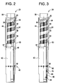
- FIG. 2 is a partial cross-sectional view of the contraction joint illustrated in FIG. 1 , according to an embodiment of the present invention
- FIG. 3 is a partial cross-sectional view of another contraction joint, according to an alternate embodiment of the present invention.
- FIG. 4 is an orthogonal view of a communication line organizer member, according to an embodiment of the present invention.
- FIG. 5 is an orthogonal view of another communication line organizer member, according to an alternate embodiment of the present invention.
- FIG. 6 is an orthogonal view of another communication line organizer member, according to an alternate embodiment of the present invention.
- FIG. 7 is an orthogonal view of another communication line organizer member, according to an alternate embodiment of the present invention.
- FIG. 8 is an orthogonal view of another communication line organizer member, according to an alternate embodiment of the present invention.
- FIG. 9 is an orthogonal view of another communication line organizer member, according to an alternate embodiment of the present invention.
- FIG. 10 is an orthogonal view of another communication line organizer member, according to an alternate embodiment of the present invention.
- the present invention generally relates to a system and methodology that facilitates the use of a contraction joint in a well completion application.
- a communication line organizer enables the use of multiple communication lines for conducting signals downhole and/or uphole without tangling, deforming or otherwise impairing the operation of the communication lines.
- the communication line organizer can be used with two or more communication lines of the same or different types. For example, hydraulic communication lines, electrical communication lines (data and/or power), optical communication lines, and/or other types of communication lines can be routed in a variety of combinations along the contraction joint for signal communication with the completion string or with other downhole components.
- the communication line organizer allows the contraction joint to contract and expand without causing the communication lines to tangle or bind.
- the communication line organizer also can be used to provide a bearing effect between the communication lines and a mandrel of the contraction joint to facilitate smooth movement of the communication lines along the outer mandrel surface during operation.
- Well system 20 comprises a completion string 22 having a contraction joint 24 .
- the completion string 22 and contraction joint 24 are deployed in a wellbore 26 that is drilled or otherwise formed in a geological formation 28 .
- the completion string 22 is deployed downhole by an appropriate deployment system 30 that may be a tubing string formed of, for example, coil tubing or jointed tubing.
- Contraction joint 24 generally is positioned between deployment system 30 and the operational well equipment 32 of completion string 22 .
- deployment system 30 extends downwardly along wellbore 26 from a wellhead 34 positioned at a surface 36 , such as a seabed floor or the surface of the earth.
- the wellbore 26 is defined by a wellbore wall 38 that may be an open wellbore wall or a wellbore casing 40 .
- the contraction joint 24 is free to move in a contracting or expanding direction to compensate for relative lineal movement between deployment system 30 and the well equipment 32 of completion string 22 .
- contraction joint 24 is designed to enable the routing of a plurality of communication lines downhole in a manner that does not tangle or detrimentally stress the communication lines during contraction and/or expansion of the contraction joint 24 .
- contraction joint 24 comprises a housing 42 slidably engaged with a mandrel 44 to enable contraction and expansion of contraction joint 24 .
- mandrel 44 slides within housing 42 along an internal passage 46 formed linearly through housing 42 so as to allow telescopic motion of mandrel 44 with respect to housing 42 .
- engagement member comprises a shear member 50 , such as a shear pin.
- a plurality of communication lines 52 is used to conduct various signals downhole and/or uphole.
- the communication lines 52 can be used to conduct signals from, for example, a surface location to well equipment 32 of completion string 22 or to other components located downhole.
- the communication lines 52 can be used in transferring signals upwardly from devices located in wellbore 26 to a surface location or to other locations.
- the communication lines may comprise hydraulic communication lines, electrical communication lines, optical communication lines, or other types of communication lines used in transferring signals. Additionally, the type and number of communication lines can vary from one well application to another. For example, three communication lines are illustrated, but other applications may utilize additional lines in many combinations as determined by the parameters of the operation.
- a line organizer 54 is utilized to manage the communication lines while enabling sufficient movement of the communication lines to accommodate the relative movement of mandrel 44 and housing 42 .
- line organizer 54 comprises a plurality of line organizer members 56 arranged along the contraction joint 24 .
- the individual line organizer members 56 may be positioned along mandrel 44 , e.g. attached to mandrel 44 along an exterior surface of the mandrel.
- the line organizer members 56 are sequentially oriented along mandrel 44 to enable the generally spiral wrapping of the communication lines 52 around mandrel 44 .
- the communication lines 52 can be routed and oriented in a variety of ways. In the embodiment illustrated, for example, the communication lines 52 extend into an upper mounting end 58 of mandrel 44 via a plurality of fittings 60 . Upper mounting end 58 is used to couple contraction joint 24 with deployment system 30 .
- the communication lines 52 extend downwardly from fittings 60 and are attached, separated, and supported by line organizer members 56 before being routed into housing 42 via line fittings 62 . In other embodiments, however, communication lines 52 can be routed along other paths, including paths that run internally or externally of upper mounting end 58 and housing 42 .
- a shroud 63 can be installed around the communication lines 52 .
- shroud 63 is installed outside communication lines 52 and line organizer 54 at the region where the communication lines extend along, e.g. are wrapped around, mandrel 44 .
- the shroud 63 protects communication lines 52 from damage during operations.
- shroud 63 is spaced from mandrel 44 a sufficient distance to serve as an envelope within which the communication lines 52 can move smoothly during contraction and expansion of contraction joint 24 .
- the shroud 63 is illustrated as attached to housing 42 , however it can be connected to other components or comprise other configurations while protecting the communication lines and ensuring smooth operation of the contraction joint.
- FIG. 3 Another embodiment of contraction joint 24 is illustrated in FIG. 3 .
- the embodiment of FIG. 3 is similar to that described with reference to FIG. 2 , but the contraction joint is re-settable.
- the housing 42 and mandrel 44 can be temporarily fixed or set at more than one position.
- housing 42 and mandrel 44 may be temporarily fixed to one another by shear member 50 , e.g. a shear pin, at a first position.
- the housing 42 and mandrel 44 also can be temporarily fixed to one another by a secondary shear member 64 , e.g. a shear pin, at a second position.
- secondary shear member 64 engages a lock ring 66 mounted along the outer surface of mandrel 44 .
- Another locking ring 68 such as a C-ring, is held in position along an interior of housing 42 by, for example, a shoulder 70 or other holding member.
- the contraction joint 24 and well equipment 32 are moved downhole with housing 42 and mandrel 44 locked at the first position via shear member 50 . Subsequently, the mandrel 44 can be pulled upwardly within housing 42 to shear the shear member 50 . The mandrel 44 is moved upwardly until lock ring 66 engages corresponding lock ring 68 to temporarily fix mandrel 44 with respect to housing 42 at the second position. During a subsequent operation, the mandrel can be pushed downwardly to shear the secondary shear member 64 . At this stage, the contraction joint 24 is free to contract and expand intermediate deployment system 30 and well equipment 32 .
- the contraction joint 24 again may comprise shroud 63 installed outside of communication lines 52 and line organizer 54 for guiding and protecting the communication lines 52 and line organizer 54 .
- Shroud 63 may be mounted to either housing 42 or mandrel 44 .
- shroud 63 may be formed as a telescoping shroud mounted to both housing 42 and mandrel 44 .
- the line organizer 54 can be formed with various numbers of line organizer members 56 positioned at various locations along mandrel 44 and/or housing 42 .
- the arrangement of line organizer members 56 is selected to accommodate the number of communication lines, the type of communication lines, the routing path for the communication lines, and the general design/application of the contraction joint 24 .
- One example of line organizer member 56 is illustrated in FIG. 4 .
- the line organizer member 56 comprises an organizer plate 72 that may be mounted to mandrel 44 or to other features of contraction joint 24 .
- the organizer plate 72 comprises one or more plate members positioned inside and/or outside of the multiple communication lines 52 .
- organizer plate 72 may comprise a backing plate 74 , positioned between mandrel 44 and communication lines 52 , and a plurality of protrusions 76 extending from backing plate 74 .
- the protrusions 76 are positioned to separate the communication lines 52 and to support the individual communication lines, i.e. provide a bearing surface for the individual communication lines. This allows the communication lines 52 to move along the surface of mandrel 44 smoothly without risk of binding or entanglement.
- the protrusion 76 or other bearing surfaces described herein, can be made from a material, e.g. non-metallic material/plastic material, selected to facilitate movement of the communication lines 52 along the surface of the mandrel.
- each line organizer member 56 comprises a retainer plate 78 having a plurality of openings 80 through which individual communication lines 52 extend.
- the retainer plate 78 is thus able to separate and support the individual communication lines while allowing movement of the communication lines 52 along the surface of mandrel 44 , thereby protecting the communication lines against binding or entanglement.
- an organizer wire 82 can be used to separate and support individual communication lines, as illustrated in FIG. 6 .
- the organizer wire 82 comprises a plurality of loop or ring sections 84 sized to fit around each communication line and thus support each individual line.
- each line organizer member 56 may be formed to hold the communication lines 52 in a group, as in the embodiments illustrated in FIGS. 7-10 .
- three communication lines 52 are held together in a triangular configuration by an outer wrap 86 or other similar member.
- the outer wrap 86 is positioned around the communication lines to securely hold the position of the communication lines and thus avoid entanglement of the communication lines during expansion and contraction of contraction joint 24 .
- the line organizer members 56 also may be formed as tubular members designed to hold the communication lines in a desired cross-sectional configuration to avoid entanglement while allowing sufficient movement of the communication lines to facilitate expansion and contraction of contraction joint 24 .
- the line organizer member 56 comprises an organizer frame 88 having a circular configuration sized to retain the desired number of communication lines at specific positions within an interior 90 of circular organizer frame 88 .
- frame 88 may be sized to hold the communication lines in the illustrated, triangular orientation when viewed in cross-section.
- Tubular organizer members also can be formed in other shapes, such as the rectangular shape illustrated in FIG. 9 .
- organizer frame 88 is rectangular and sized to retain a plurality of communication lines 52 in a linear arrangement within interior 90 .
- the interior 90 may have a generally oval shape designed to secure the outlying communication lines as well as those therebetween when the communication lines 52 are viewed in cross-section.
- FIG. 10 Another example is illustrated in which the organizer frame 88 has a generally square shape sized to secure the orientation of, for example, four communication lines 52 .
- the size and shape of organizer frame 88 can be adjusted according to the type and number of communication lines.
- the design of contraction joint 24 and the overall completion string 22 can be selected according to the desired well operation and well environment. Additionally, the type and number of communication lines also can change depending on the specific application for which they are used in conducting signals downhole and/or uphole.
- the line organizers also can have differing numbers of line organizer members and line organizer member configurations to properly secure the communication line orientation while enabling the free contraction and expansion of the contraction joint.
Landscapes
- Engineering & Computer Science (AREA)
- Geology (AREA)
- Mining & Mineral Resources (AREA)
- Life Sciences & Earth Sciences (AREA)
- General Life Sciences & Earth Sciences (AREA)
- Fluid Mechanics (AREA)
- Environmental & Geological Engineering (AREA)
- Physics & Mathematics (AREA)
- Mechanical Engineering (AREA)
- Geochemistry & Mineralogy (AREA)
- Laying Of Electric Cables Or Lines Outside (AREA)
- Prostheses (AREA)
- Cable Accessories (AREA)
- Superconductors And Manufacturing Methods Therefor (AREA)
- Ceramic Products (AREA)
- Vending Machines For Individual Products (AREA)
Priority Applications (8)
| Application Number | Priority Date | Filing Date | Title |
|---|---|---|---|
| US11/850,392 US7806190B2 (en) | 2007-09-24 | 2007-09-24 | Contraction joint system |
| MX2010003066A MX2010003066A (es) | 2007-09-24 | 2008-08-18 | Sistema de junta de contratacion. |
| PCT/US2008/073419 WO2009042310A1 (en) | 2007-09-24 | 2008-08-18 | Contraction joint system |
| GB1004637.3A GB2467458B (en) | 2007-09-24 | 2008-08-18 | Contraction joint system |
| BRPI0816349A BRPI0816349B8 (pt) | 2007-09-24 | 2008-08-18 | sistema de junta de contração e método para implantação de uma completação de poço com uma junta de contração |
| RU2010116173/03A RU2472917C2 (ru) | 2007-09-24 | 2008-08-18 | Система компенсационного скользящего стыка |
| CA2698746A CA2698746A1 (en) | 2007-09-24 | 2008-08-18 | Contraction joint system |
| NO20100522A NO345009B1 (no) | 2007-09-24 | 2010-04-13 | Kontraksjonsskjøtsystem |
Applications Claiming Priority (1)
| Application Number | Priority Date | Filing Date | Title |
|---|---|---|---|
| US11/850,392 US7806190B2 (en) | 2007-09-24 | 2007-09-24 | Contraction joint system |
Publications (2)
| Publication Number | Publication Date |
|---|---|
| US20090078430A1 US20090078430A1 (en) | 2009-03-26 |
| US7806190B2 true US7806190B2 (en) | 2010-10-05 |
Family
ID=40470414
Family Applications (1)
| Application Number | Title | Priority Date | Filing Date |
|---|---|---|---|
| US11/850,392 Active 2028-03-15 US7806190B2 (en) | 2007-09-24 | 2007-09-24 | Contraction joint system |
Country Status (8)
| Country | Link |
|---|---|
| US (1) | US7806190B2 (pt) |
| BR (1) | BRPI0816349B8 (pt) |
| CA (1) | CA2698746A1 (pt) |
| GB (1) | GB2467458B (pt) |
| MX (1) | MX2010003066A (pt) |
| NO (1) | NO345009B1 (pt) |
| RU (1) | RU2472917C2 (pt) |
| WO (1) | WO2009042310A1 (pt) |
Cited By (10)
| Publication number | Priority date | Publication date | Assignee | Title |
|---|---|---|---|---|
| US20100224375A1 (en) * | 2009-03-09 | 2010-09-09 | Schlumberger Technology Corporation | Re-settable and anti-rotational contraction joint with control lines |
| US20130025880A1 (en) * | 2011-07-30 | 2013-01-31 | Halliburton Energy Services, Inc. | Traversing a travel joint with a fluid line |
| US11795767B1 (en) | 2020-11-18 | 2023-10-24 | Schlumberger Technology Corporation | Fiber optic wetmate |
| US12104441B2 (en) | 2020-06-03 | 2024-10-01 | Schlumberger Technology Corporation | System and method for connecting multiple stage completions |
| US12129714B2 (en) | 2021-01-18 | 2024-10-29 | Schlumberger Technology Corporation | Fiber electric wet mate |
| US12281524B2 (en) | 2021-04-02 | 2025-04-22 | Schlumberger Technology Corporation | Contraction joint for intelligent completion and downhole completion system |
| US12281523B2 (en) | 2021-03-12 | 2025-04-22 | Schlumberger Technology Corporation | Downhole connector orientation for wetmate connectors |
| US12297707B2 (en) | 2021-04-07 | 2025-05-13 | Schlumberger Technology Corporation | Latch assembly |
| US12385329B2 (en) | 2021-06-22 | 2025-08-12 | Schlumberger Technology Corporation | Contraction joint for fiber optics intelligent completion |
| US12553296B2 (en) | 2022-05-25 | 2026-02-17 | Schlumberger Technology Corporation | Downhole hydraulic mechanical lock |
Families Citing this family (15)
| Publication number | Priority date | Publication date | Assignee | Title |
|---|---|---|---|---|
| US20080223585A1 (en) * | 2007-03-13 | 2008-09-18 | Schlumberger Technology Corporation | Providing a removable electrical pump in a completion system |
| US7810560B2 (en) * | 2008-10-27 | 2010-10-12 | Weatherford/Lamb, Inc. | Expansion joint with communication medium bypass |
| WO2014089132A1 (en) * | 2012-12-04 | 2014-06-12 | Schlumberger Canada Limited | Tubing movement compensation joint |
| RU2606034C1 (ru) | 2013-02-02 | 2017-01-10 | Шлюмбергер Текнолоджи Б.В. | Телеметрическое оборудование для систем с многофазным электрическим двигателем |
| CA2898734C (en) * | 2013-02-21 | 2020-08-04 | William M. Richards | Method and system for directing control lines along a travel joint |
| US9650846B2 (en) * | 2013-12-09 | 2017-05-16 | Baker Hughes Incorporated | Completion systems including reduced stress expandable control lines |
| WO2016003393A1 (en) | 2014-06-30 | 2016-01-07 | Halliburton Energy Services, Inc. | Helical control line connector for connecting to a downhole completion receptacle |
| WO2016003388A1 (en) | 2014-06-30 | 2016-01-07 | Halliburton Energy Services, Inc. | Downhole control line connector |
| US9523243B2 (en) * | 2014-06-30 | 2016-12-20 | Halliburton Energy Services, Inc. | Helical dry mate control line connector |
| WO2016003394A1 (en) * | 2014-06-30 | 2016-01-07 | Halliburton Energy Services, Inc. | Downhole expandable control line connector |
| WO2016003397A1 (en) * | 2014-06-30 | 2016-01-07 | Halliburton Energy Services, Inc. | Downhole expandable control line connector |
| US10060196B2 (en) | 2014-06-30 | 2018-08-28 | Halliburton Energy Services, Inc. | Methods of coupling a downhole control line connector |
| US10919729B2 (en) * | 2014-11-17 | 2021-02-16 | Halliburton Energy Services, Inc. | Self-retractable coiled electrical cable |
| CN108131104B (zh) * | 2016-11-30 | 2019-10-08 | 北京海蓝石油技术开发有限公司 | 一种导流式扶正器和一种随钻测量设备 |
| US12338692B2 (en) * | 2023-05-31 | 2025-06-24 | Halliburton Energy Services, Inc. | Swivel sub with biasing member |
Citations (10)
| Publication number | Priority date | Publication date | Assignee | Title |
|---|---|---|---|---|
| US6182750B1 (en) | 1996-11-20 | 2001-02-06 | Schlumberger Technology Corporation | Device for performing downhole functions |
| US6349770B1 (en) * | 2000-01-14 | 2002-02-26 | Weatherford/Lamb, Inc. | Telescoping tool |
| US20050072564A1 (en) | 2003-10-07 | 2005-04-07 | Tommy Grigsby | Gravel pack completion with fluid loss control fiber optic wet connect |
| US6920932B2 (en) | 2003-04-07 | 2005-07-26 | Weatherford/Lamb, Inc. | Joint for use with expandable tubulars |
| US20060000618A1 (en) | 2004-07-01 | 2006-01-05 | Schlumberger Technology Corporation | Line Slack Compensator |
| US20060260817A1 (en) | 2005-05-21 | 2006-11-23 | Schlumberger Technology Corporation | Downhole Connection System |
| US7222676B2 (en) | 2000-12-07 | 2007-05-29 | Schlumberger Technology Corporation | Well communication system |
| US20070144746A1 (en) | 2005-11-29 | 2007-06-28 | Schlumberger Technology Corporation | System and Method for Connecting Multiple Stage Completions |
| US20080011907A1 (en) * | 2006-07-13 | 2008-01-17 | Jacobsma Paul M | Intravenous line organizer |
| US20090032268A1 (en) * | 2007-08-01 | 2009-02-05 | Blanton James R | Installation of lines in well tools |
Family Cites Families (3)
| Publication number | Priority date | Publication date | Assignee | Title |
|---|---|---|---|---|
| SU781479A2 (ru) * | 1979-04-03 | 1980-11-23 | Ордена Ленина, Ордена Октябрьской Революции И Ордена Трудового Красного Знамени Производственное Объединение "Ростсельмаш" | Устройство дл поддержани гибких трубопроводов, имеющих изгиб |
| RU2267199C1 (ru) * | 2004-03-29 | 2005-12-27 | Пермяков Олег Львович | Устройство для крепления кабеля |
| RU65168U1 (ru) * | 2007-03-21 | 2007-07-27 | Эдуард Патваканович Багдасарян | Устройство для прокладки средств связи в переходах трубопроводов (варианты) |
-
2007
- 2007-09-24 US US11/850,392 patent/US7806190B2/en active Active
-
2008
- 2008-08-18 CA CA2698746A patent/CA2698746A1/en not_active Abandoned
- 2008-08-18 WO PCT/US2008/073419 patent/WO2009042310A1/en not_active Ceased
- 2008-08-18 MX MX2010003066A patent/MX2010003066A/es not_active Application Discontinuation
- 2008-08-18 RU RU2010116173/03A patent/RU2472917C2/ru not_active IP Right Cessation
- 2008-08-18 BR BRPI0816349A patent/BRPI0816349B8/pt active IP Right Grant
- 2008-08-18 GB GB1004637.3A patent/GB2467458B/en active Active
-
2010
- 2010-04-13 NO NO20100522A patent/NO345009B1/no unknown
Patent Citations (12)
| Publication number | Priority date | Publication date | Assignee | Title |
|---|---|---|---|---|
| US6182750B1 (en) | 1996-11-20 | 2001-02-06 | Schlumberger Technology Corporation | Device for performing downhole functions |
| US6349770B1 (en) * | 2000-01-14 | 2002-02-26 | Weatherford/Lamb, Inc. | Telescoping tool |
| US7222676B2 (en) | 2000-12-07 | 2007-05-29 | Schlumberger Technology Corporation | Well communication system |
| US6920932B2 (en) | 2003-04-07 | 2005-07-26 | Weatherford/Lamb, Inc. | Joint for use with expandable tubulars |
| US20050072564A1 (en) | 2003-10-07 | 2005-04-07 | Tommy Grigsby | Gravel pack completion with fluid loss control fiber optic wet connect |
| US20060000618A1 (en) | 2004-07-01 | 2006-01-05 | Schlumberger Technology Corporation | Line Slack Compensator |
| US20060260817A1 (en) | 2005-05-21 | 2006-11-23 | Schlumberger Technology Corporation | Downhole Connection System |
| US20060260803A1 (en) | 2005-05-21 | 2006-11-23 | Schlumberger Technology Corporation | Downhole Connection System |
| US20060260818A1 (en) | 2005-05-21 | 2006-11-23 | Schlumberger Technology Corporation | Downhole Connection System |
| US20070144746A1 (en) | 2005-11-29 | 2007-06-28 | Schlumberger Technology Corporation | System and Method for Connecting Multiple Stage Completions |
| US20080011907A1 (en) * | 2006-07-13 | 2008-01-17 | Jacobsma Paul M | Intravenous line organizer |
| US20090032268A1 (en) * | 2007-08-01 | 2009-02-05 | Blanton James R | Installation of lines in well tools |
Cited By (13)
| Publication number | Priority date | Publication date | Assignee | Title |
|---|---|---|---|---|
| US8061430B2 (en) * | 2009-03-09 | 2011-11-22 | Schlumberger Technology Corporation | Re-settable and anti-rotational contraction joint with control lines |
| US20100224375A1 (en) * | 2009-03-09 | 2010-09-09 | Schlumberger Technology Corporation | Re-settable and anti-rotational contraction joint with control lines |
| US20130025880A1 (en) * | 2011-07-30 | 2013-01-31 | Halliburton Energy Services, Inc. | Traversing a travel joint with a fluid line |
| US8915304B2 (en) * | 2011-07-30 | 2014-12-23 | Halliburton Energy Services, Inc. | Traversing a travel joint with a fluid line |
| US12104441B2 (en) | 2020-06-03 | 2024-10-01 | Schlumberger Technology Corporation | System and method for connecting multiple stage completions |
| US12104440B2 (en) | 2020-11-18 | 2024-10-01 | Schlumberger Technology Corporation | Fiber optic wetmate |
| US11795767B1 (en) | 2020-11-18 | 2023-10-24 | Schlumberger Technology Corporation | Fiber optic wetmate |
| US12129714B2 (en) | 2021-01-18 | 2024-10-29 | Schlumberger Technology Corporation | Fiber electric wet mate |
| US12281523B2 (en) | 2021-03-12 | 2025-04-22 | Schlumberger Technology Corporation | Downhole connector orientation for wetmate connectors |
| US12281524B2 (en) | 2021-04-02 | 2025-04-22 | Schlumberger Technology Corporation | Contraction joint for intelligent completion and downhole completion system |
| US12297707B2 (en) | 2021-04-07 | 2025-05-13 | Schlumberger Technology Corporation | Latch assembly |
| US12385329B2 (en) | 2021-06-22 | 2025-08-12 | Schlumberger Technology Corporation | Contraction joint for fiber optics intelligent completion |
| US12553296B2 (en) | 2022-05-25 | 2026-02-17 | Schlumberger Technology Corporation | Downhole hydraulic mechanical lock |
Also Published As
| Publication number | Publication date |
|---|---|
| BRPI0816349B8 (pt) | 2020-07-07 |
| BRPI0816349A2 (pt) | 2018-07-31 |
| CA2698746A1 (en) | 2009-04-02 |
| GB2467458A (en) | 2010-08-04 |
| BRPI0816349B1 (pt) | 2020-06-23 |
| WO2009042310A1 (en) | 2009-04-02 |
| GB201004637D0 (en) | 2010-05-05 |
| RU2472917C2 (ru) | 2013-01-20 |
| NO20100522A1 (no) | 2010-04-23 |
| NO345009B1 (no) | 2020-08-17 |
| RU2010116173A (ru) | 2011-11-10 |
| MX2010003066A (es) | 2010-04-07 |
| GB2467458B (en) | 2012-03-28 |
| US20090078430A1 (en) | 2009-03-26 |
Similar Documents
| Publication | Publication Date | Title |
|---|---|---|
| US7806190B2 (en) | Contraction joint system | |
| US7866405B2 (en) | Securement of lines to well sand control screens | |
| EP2959097B1 (en) | Method and system for directing control lines along a travel joint | |
| US8371372B2 (en) | Installation of tubular strings with lines secured thereto in subterranean wells | |
| US20040144535A1 (en) | Post installation cured braided continuous composite tubular | |
| US11525340B2 (en) | System and methodology for high pressure alternate path | |
| CN110832242A (zh) | 弯曲限制器 | |
| WO2012098464A2 (en) | Deployment of fibre optic cables and joining of tubing for use in boreholes | |
| US6881079B2 (en) | Technique for providing power to a completion used in a subterranean environment | |
| EP2700864A2 (en) | Protective member for a utility line | |
| US20140041878A1 (en) | Hybrid Riser System | |
| US9016385B2 (en) | Securing connections in alternate path well screens | |
| US10280694B2 (en) | Contraction joint with multiple telescoping sections | |
| US9534454B2 (en) | Method and apparatus for storing cable in a wellbore | |
| EP2699755B1 (en) | Hybrid riser system | |
| EP3150795B1 (en) | Sand control screen | |
| WO2017116968A1 (en) | Use of structural member to provide optical fiber in a wellbore | |
| US10253583B2 (en) | In situ length expansion of a bend stiffener |
Legal Events
| Date | Code | Title | Description |
|---|---|---|---|
| AS | Assignment |
Owner name: SCHLUMBERGER TECHNOLOGY CORPORATION, TEXAS Free format text: ASSIGNMENT OF ASSIGNORS INTEREST;ASSIGNOR:DU, MICHAEL H.;REEL/FRAME:019962/0501 Effective date: 20070924 |
|
| STCF | Information on status: patent grant |
Free format text: PATENTED CASE |
|
| FPAY | Fee payment |
Year of fee payment: 4 |
|
| MAFP | Maintenance fee payment |
Free format text: PAYMENT OF MAINTENANCE FEE, 8TH YEAR, LARGE ENTITY (ORIGINAL EVENT CODE: M1552) Year of fee payment: 8 |
|
| MAFP | Maintenance fee payment |
Free format text: PAYMENT OF MAINTENANCE FEE, 12TH YEAR, LARGE ENTITY (ORIGINAL EVENT CODE: M1553); ENTITY STATUS OF PATENT OWNER: LARGE ENTITY Year of fee payment: 12 |