US7810715B2 - Self-service terminal - Google Patents
Self-service terminal Download PDFInfo
- Publication number
- US7810715B2 US7810715B2 US12/012,177 US1217708A US7810715B2 US 7810715 B2 US7810715 B2 US 7810715B2 US 1217708 A US1217708 A US 1217708A US 7810715 B2 US7810715 B2 US 7810715B2
- Authority
- US
- United States
- Prior art keywords
- component
- self
- fascia
- service terminal
- energizable
- Prior art date
- Legal status (The legal status is an assumption and is not a legal conclusion. Google has not performed a legal analysis and makes no representation as to the accuracy of the status listed.)
- Active, expires
Links
Images



Classifications
-
- G—PHYSICS
- G07—CHECKING-DEVICES
- G07F—COIN-FREED OR LIKE APPARATUS
- G07F19/00—Complete banking systems; Coded card-freed arrangements adapted for dispensing or receiving monies or the like and posting such transactions to existing accounts, e.g. automatic teller machines
- G07F19/20—Automatic teller machines [ATMs]
- G07F19/201—Accessories of ATMs
-
- G—PHYSICS
- G06—COMPUTING OR CALCULATING; COUNTING
- G06Q—INFORMATION AND COMMUNICATION TECHNOLOGY [ICT] SPECIALLY ADAPTED FOR ADMINISTRATIVE, COMMERCIAL, FINANCIAL, MANAGERIAL OR SUPERVISORY PURPOSES; SYSTEMS OR METHODS SPECIALLY ADAPTED FOR ADMINISTRATIVE, COMMERCIAL, FINANCIAL, MANAGERIAL OR SUPERVISORY PURPOSES, NOT OTHERWISE PROVIDED FOR
- G06Q20/00—Payment architectures, schemes or protocols
- G06Q20/08—Payment architectures
- G06Q20/10—Payment architectures specially adapted for electronic funds transfer [EFT] systems; specially adapted for home banking systems
- G06Q20/108—Remote banking, e.g. home banking
- G06Q20/1085—Remote banking, e.g. home banking involving automatic teller machines [ATMs]
-
- G—PHYSICS
- G07—CHECKING-DEVICES
- G07F—COIN-FREED OR LIKE APPARATUS
- G07F19/00—Complete banking systems; Coded card-freed arrangements adapted for dispensing or receiving monies or the like and posting such transactions to existing accounts, e.g. automatic teller machines
- G07F19/20—Automatic teller machines [ATMs]
-
- G—PHYSICS
- G07—CHECKING-DEVICES
- G07F—COIN-FREED OR LIKE APPARATUS
- G07F19/00—Complete banking systems; Coded card-freed arrangements adapted for dispensing or receiving monies or the like and posting such transactions to existing accounts, e.g. automatic teller machines
- G07F19/20—Automatic teller machines [ATMs]
- G07F19/205—Housing aspects of ATMs
Definitions
- the present invention relates to a self-service terminal.
- ATM automated teller machine
- ATMs contain quite a number of devices, such as a cash dispenser, a card reader, a receipt printer, and the like. These devices enable the ATM to perform transactions for customers. Access to these devices may be provided from the rear of the ATM, and/or from the front of the ATM. Where front access is provided, an ATM is typically provided with a fascia on the front of the ATM that either (i) pivots upwards, or (ii) racks out (slides out like a drawer). Whichever mounting mechanism is used (a pivot or a slide), when the fascia is opened, the devices mounted within the ATM are exposed to enable an ATM technician to gain access to them.
- a fascia on the front of the ATM that either (i) pivots upwards, or (ii) racks out (slides out like a drawer). Whichever mounting mechanism is used (a pivot or a slide), when the fascia is opened, the devices mounted within the ATM are exposed to enable an ATM technician to gain access to them.
- the invention generally provides an improved fascia for a self-service terminal.
- a fascia for a self-service terminal comprising: a first component located in fixed spatial relation to a plurality of devices mounted within the self-service terminal, and a second component mounted in movable spatial relation to at least one other device mounted within the self-service terminal, the second component being movable relative to the first component to provide access to the devices mounted within the self-service terminal when the second component is opened, and providing a unitary sealed fascia when the second component is closed.
- the first component may be an inner component and the second component may be an outer component surrounding the inner component.
- the first component may include a customer display mounted thereto. This allows a service technician (such as an ATM technician) to view the customer display (which may be displaying instructions for the service technician) while performing a servicing operation. This has the advantage that a secondary display for use in performing servicing operations may not be required.
- a service technician such as an ATM technician
- the first component may include apertures (such as slots), each aperture aligning with an entry/exit port on a central device.
- These central devices may include: a card reader, a receipt printer, a statement printer, a passbook printer, and the like.
- the first component and its associated central devices may be mounted on a tray sliding on a rail mechanism, thereby allowing the first component and the central devices to be accessed by sliding the tray out from a closed position, where the first component is fully racked (and latched) into the self-service terminal, to an open position, where the first component is fully racked out.
- the second component may be pivotably mounted to an upper portion of the self-service terminal, thereby allowing the second component to pivot upwards to an open position at which the devices within the self-service terminal are exposed, and downwards to a closed position, at which the second component is in sealing engagement with the first component and the second component is latched to the self-service terminal.
- the second component may be slideably mounted to the self-service terminal, thereby allowing the second component to be racked out from a closed position to an open position.
- the second component may include an inwardly projecting portion for urging a fixture (such as a sloping bar, a hooked stanchion, or the like) on the sliding tray rail mechanism towards a closed position. If the first component is not in the closed position when the second component is pivoted downwards, then the projecting portion engages with the fixture and moves the sliding tray mechanism to the closed position as a result of the second component being moved to its closed position.
- a fixture such as a sloping bar, a hooked stanchion, or the like
- the inwardly projecting portion may be provided by a sheet metal enclosure for a light box.
- a sealing gasket may be provided on one or both of the first component and the second component.
- the sealing gasket may surround the first component.
- the second component may provide access to the self-service terminal interior, and also provide access to a cash dispenser shutter.
- the second component may be mounted in movable spatial relation to a cash dispenser and/or a banknote depository mounted within the self-service terminal.
- the fascia may provide a customer interface (including, for example, slots, a display, a keypad, and the like) in a first plane, and an information panel in a second plane transverse to the first plane, the information panel comprising a first energizable graphic and a second energizable graphic.
- a customer interface including, for example, slots, a display, a keypad, and the like
- an information panel in a second plane transverse to the first plane, the information panel comprising a first energizable graphic and a second energizable graphic.
- the information panel may be provided on the second component.
- the information panel may be provided on an edge of the second component.
- the first and second energizable graphics may be provided as two separate series of LEDs mounted on a common printed circuit board.
- the first series may be in the form of a single or double headed arrow, the second series may be in the form of a cross.
- the first energizable graphic may be in the form of an arrow (such as a green single or double-headed arrow pointing to the front of the terminal), the second energizable graphic may be in the form of a cross (such as a red cross).
- Each graphic is preferably separately energizable, so that only one graphic is energized at any given time.
- the fascia may be for use with a drive-up self-service terminal, such as a drive-up ATM.
- vehicle drivers can ascertain from a distance whether the terminal is operational. Where multiple self-service terminals are used in a location, each in a different lane, a vehicle driver can select a lane having an operational self-service terminal, as indicated by the information panel.
- a self-service terminal including the fascia of the first aspect.
- a self-service terminal that has a dual component fascia.
- One component may be used to ensure that critical alignment with certain devices (for example a card reader and various printers) is always maintained, the other component may be used to ensure that sufficient access is provided to the self-service terminal interior to ensure that servicing operations can be easily and reliably performed.
- a self-service terminal fascia comprising an information panel disposed on a plane transverse to the plane of a customer interface used by a customer of the terminal to conduct a transaction, the information panel comprising a first energizable graphic for indicating that the self-service terminal is in service, and a second energizable graphic for indicating that the self-service terminal is not in service.
- the first energizable graphic may be an arrow, and the second energizable graphic may be a cross.
- the first energizable graphic may be green, the second energizable graphic may be red.
- the first and second energizable graphics may be co-located on the same general area of the information panel.
- a fascia for a self-service terminal comprising: a first component located in fixed spatial relation to a plurality of devices mounted within the self-service terminal, and a second component mounted in movable spatial relation the first component to provide access to the devices mounted within the self-service terminal when the second component is opened.
- FIG. 1 is a perspective view of a self-service terminal according to one embodiment of the present invention showing a part (the second fascia component) in the open position;
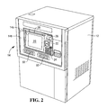
- FIG. 2 is a perspective view of the self-service terminal of FIG. 1 showing the second fascia component in the closed position;
- FIG. 3 is a side view of the self-service terminal of FIG. 1 showing an information panel
- FIG. 4 is an enlarged view of the information panel of FIG. 3 in a first energized state indicating that the terminal of FIG. 1 is in service;
- FIG. 5 is an enlarged view of the information panel of FIG. 3 in a second energized state indicating that the terminal of FIG. 1 is out of service.
- FIG. 1 is a perspective view of a self-service terminal 10 (in the form of a drive-up ATM) according to one embodiment of the present invention. This is the view that would be seen by an ATM technician during a maintenance (servicing) operation.
- the ATM 10 comprises a housing 12 to which is coupled a two-part fascia 14 .
- the two-part fascia 14 comprises a first (inner) fascia component 14 a , and a second (outer) fascia component 14 b defining a central aperture dimensioned to accommodate the inner fascia component 14 a in sealing engagement when the outer fascia component 14 b is in a closed position.
- the inner fascia component 14 a includes a perimeter gasket 16 to ensure a water-tight seal with the outer fascia component 14 b.
- the inner fascia component 14 a includes a display 20 mounted thereon, a card reader entrance/exit port 22 including an anti-fraud hologram, an encrypting PINpad device 24 , a receipt printer slot 26 , and a statement printer slot 28 .
- the inner fascia component 14 a is mounted on a device tray 30 that supports various internal ATM devices, (referred to herein as central devices) such as a card reader (not shown) aligned with the card reader entrance/exit port 22 ; a receipt printer 34 aligned with the receipt printer slot 26 ; and a statement printer 36 aligned with the statement printer slot 28 .
- various internal ATM devices such as a card reader (not shown) aligned with the card reader entrance/exit port 22 ; a receipt printer 34 aligned with the receipt printer slot 26 ; and a statement printer 36 aligned with the statement printer slot 28 .
- the device tray 30 is slideably mounted on a rail mechanism 40 , thereby allowing the device tray 30 and the devices 20 , 24 , 34 , 36 supported thereon, to be racked horizontally out of the ATM 10 for servicing by an ATM technician, and to be racked back into the ATM 10 when servicing is complete.
- the inner fascia component 14 a is fixed relative to the card reader (not shown), receipt printer 34 , and statement printer 36 . This ensures that there is no misalignment between each device supported by the tray 30 and its associated slot or port. In some ATMs, up to 60% of service callouts requiring a visit from an ATM technician are attributable to misalignment of devices with their respective slots or the devices not being properly racked back in place prior to closing the fascia. Since there is no relative movement between the inner fascia component 14 a and the devices supported by the tray 30 , these misalignment problems are greatly reduced in this embodiment.
- the outer fascia component 14 b is pivotably mounted by hinges 50 (only one of which is shown in FIG. 1 ) to an upper portion of the ATM 10 , and is maintained in an open position (as shown in FIG. 1 ) by a gas spring 52 .
- the outer fascia component 14 b includes a projecting portion 54 defining an edge 56 for engaging with a sloping bar 58 on the device tray 30 .
- the bar 58 slopes from a high position at the rear of the device tray 30 to a low position at the front of the device tray 30 where the inner fascia component 14 a is mounted.
- the outer fascia component 14 b is lowered while the inner fascia component 14 a is racked out, then the edge 56 of the projecting portion 54 comes into contact with the bar 58 . If the outer fascia component 14 b continues to be lowered, then it urges the bar 58 and the device tray 30 to the closed position as the outer fascia component 14 b is lowered.
- FIG. 2 is a perspective view of the ATM 10 showing the inner and outer fascia components 14 in the closed position.
- the outer fascia component 14 b also includes a cash dispenser slot 60 and a banknote deposit slot 62 .
- the cash dispenser slot 60 aligns with a cash dispenser device 64 that is located in a safe (not shown) within a lower portion of the ATM 10 ; and the banknote depository slot 62 aligns with a banknote depository device 66 that is also located in the safe (not shown) within a lower portion of the ATM 10 .
- the inner fascia component 14 a will be closed automatically by the action of the projecting portion 54 and the sloping bar 58 , thereby preventing damage to the inner fascia component 14 a and device tray 30 .
- FIG. 3 is a side view of the ATM 10 .
- the outer fascia component 14 b includes an information panel 70 .
- the information panel 70 has a first energizable graphic 72 and a second energizable graphic 74 .
- the first energizable graphic 72 is in the form of a series of green LEDs forming a double-headed arrow pointing towards a front area of the ATM 10 , which signifies to ATM customers approaching the ATM 10 from the side, such as vehicle drivers, that the ATM 10 is in service.
- the second energizable graphic 74 is in the form of a series of red LEDs forming a cross, which signifies to ATM customers approaching the ATM 10 from the side, such as vehicle drivers, that the ATM 10 is out of service.
- the series of green LEDs and the series of red LEDs are disposed on the same circuit board and covered by a translucent diffusing sheet, so that only the green double-headed arrow (not the red cross) is visible when the first energizable graphic 72 is activated; and only the red cross (not the green double-headed arrow) is visible when the second energizable graphic 74 is activated.
- the first and second energizable graphics 72 , 74 are separately energized on a mutually exclusive basis, so that if the first energizable graphic 72 is illuminated then the second energizable graphic 74 is not illuminated, and vice versa.
- an ATM controller such as a PC core, illuminates the first energizable graphic 72 (the green arrow); whereas, when the ATM 10 is not operating correctly (that is, when the ATM 10 is not in service), the ATM controller (not shown) illuminates the second energizable graphic 74 (the red cross). This enables prospective customers approaching the ATM 10 to see from a distance whether the ATM 10 is in operation or not.
- the information panel 70 provides an indication of which ATMs are in service. This avoids drivers having to reverse or pass through the drive-up lane and rejoin a queue to select another lane with an in-service ATM.
- the ATM 10 provides a highly visible indicator that shows the status of the ATM 10 . This indicator is highly visible and can be seen before the driver needs to select a lane.
- a self-service terminal other than an ATM may be used, such as a self-checkout terminal.
- the outer fascia component may rack out rather than pivot up.
- the outer fascia component may include an aperture for receiving deposited cheques.
- the aperture may align, when the outer component is in the closed position, with a cheque processing device mounted within the ATM.
- the information panel may have different graphics than those described (for example, a tick instead of an arrow), and the colors may be different to those described (for example, black instead of red).
Landscapes
- Business, Economics & Management (AREA)
- Accounting & Taxation (AREA)
- Finance (AREA)
- Physics & Mathematics (AREA)
- General Physics & Mathematics (AREA)
- Economics (AREA)
- Development Economics (AREA)
- Strategic Management (AREA)
- General Business, Economics & Management (AREA)
- Engineering & Computer Science (AREA)
- Theoretical Computer Science (AREA)
- Control Of Vending Devices And Auxiliary Devices For Vending Devices (AREA)
- Financial Or Insurance-Related Operations Such As Payment And Settlement (AREA)
- Cash Registers Or Receiving Machines (AREA)
Priority Applications (3)
| Application Number | Priority Date | Filing Date | Title |
|---|---|---|---|
| US12/012,177 US7810715B2 (en) | 2008-01-31 | 2008-01-31 | Self-service terminal |
| EP09150976.0A EP2088565B1 (fr) | 2008-01-31 | 2009-01-20 | Terminal en libre-service |
| CN200910126705.7A CN101510338B (zh) | 2008-01-31 | 2009-02-01 | 自助终端 |
Applications Claiming Priority (1)
| Application Number | Priority Date | Filing Date | Title |
|---|---|---|---|
| US12/012,177 US7810715B2 (en) | 2008-01-31 | 2008-01-31 | Self-service terminal |
Publications (2)
| Publication Number | Publication Date |
|---|---|
| US20090195993A1 US20090195993A1 (en) | 2009-08-06 |
| US7810715B2 true US7810715B2 (en) | 2010-10-12 |
Family
ID=40626532
Family Applications (1)
| Application Number | Title | Priority Date | Filing Date |
|---|---|---|---|
| US12/012,177 Active 2029-02-26 US7810715B2 (en) | 2008-01-31 | 2008-01-31 | Self-service terminal |
Country Status (3)
| Country | Link |
|---|---|
| US (1) | US7810715B2 (fr) |
| EP (1) | EP2088565B1 (fr) |
| CN (1) | CN101510338B (fr) |
Cited By (5)
| Publication number | Priority date | Publication date | Assignee | Title |
|---|---|---|---|---|
| US20100264208A1 (en) * | 2007-11-23 | 2010-10-21 | Nikolai Lipkowitsch | Device for receiving and/or issuing payment means and/or for processing value documents |
| US8127981B1 (en) * | 2007-09-07 | 2012-03-06 | Diebold Self-Service Systems Division Of Diebold, Incorporated | Banking system controlled responsive to data bearing records |
| US8485433B2 (en) * | 2011-10-31 | 2013-07-16 | Ncr Corporation | Terminal fascia |
| US20140165473A1 (en) * | 2012-12-18 | 2014-06-19 | Ncr Corporation | Self-aligning cover for an sst |
| US20240052686A1 (en) * | 2020-12-18 | 2024-02-15 | Jason Augustin KORDA | Retractable housing assembly |
Families Citing this family (12)
| Publication number | Priority date | Publication date | Assignee | Title |
|---|---|---|---|---|
| US8181855B2 (en) * | 2007-08-29 | 2012-05-22 | Diebold Self-Service Systems Division Of Diebold, Incorporated | Banking system controlled responsive to data bearing records |
| USD651784S1 (en) * | 2008-12-18 | 2012-01-03 | Ncr Corporation | Self-service terminal |
| US8690058B2 (en) * | 2009-10-23 | 2014-04-08 | Nidec Sankyo Corporation | Card reader |
| JP2013073391A (ja) * | 2011-09-27 | 2013-04-22 | Oki Electric Ind Co Ltd | 自動取引装置 |
| CN102620128B (zh) * | 2012-03-14 | 2014-12-03 | 广州恩次元信息科技有限公司 | 一种具有双操作平台的自助设备 |
| CN102968855A (zh) * | 2012-11-13 | 2013-03-13 | 无锡市永创电控器材有限公司 | Atm软拉索开关机构 |
| US9019089B2 (en) * | 2013-03-14 | 2015-04-28 | Ncr Corporation | User interface for an SST |
| CN103346954A (zh) * | 2013-06-17 | 2013-10-09 | 北京印刷学院 | 一种邮件收发装置 |
| JP6303921B2 (ja) * | 2014-08-25 | 2018-04-04 | 沖電気工業株式会社 | 媒体取引装置 |
| CN206282175U (zh) * | 2016-08-25 | 2017-06-27 | 京东方科技集团股份有限公司 | 折叠式显示装置及显示设备 |
| CN108010190A (zh) * | 2017-12-12 | 2018-05-08 | 柳州市北龟农业科技孵化器有限公司 | 一种企业咨询服务装置 |
| CN116156805A (zh) * | 2022-12-27 | 2023-05-23 | 航天信息股份有限公司 | 自助机操作面板翻转装置及自助服务设备 |
Citations (7)
| Publication number | Priority date | Publication date | Assignee | Title |
|---|---|---|---|---|
| US5642922A (en) | 1994-03-15 | 1997-07-01 | Interbold | Automated teller machine monitor mount |
| EP0924668A2 (fr) | 1997-12-20 | 1999-06-23 | Ncr International Inc. | Terminal en libre-service amélioré |
| US20020074393A1 (en) * | 1998-08-20 | 2002-06-20 | James M. Anderson | Self-service terminal |
| US20040099726A1 (en) | 2002-11-25 | 2004-05-27 | Diebold Self Service Systems Division Of Diebold, Incorporated | Automated banking machine housing with improved service access |
| US20040222296A1 (en) | 2003-03-10 | 2004-11-11 | Diebold Self-Service Systems Division Of Diebold, Incorporated | Cash dispensing automated banking machine with fascia and component self-alignment |
| US7416111B1 (en) * | 2004-03-09 | 2008-08-26 | Diebold Self-Service Systems, Division Of Diebold, Incorporated | Cash dispensing automated banking machine and method |
| US7661584B1 (en) * | 2005-06-03 | 2010-02-16 | Diebold Self-Service Systems, Division Of Diebold, Incorporated | Enclosure for automated banking machine |
Family Cites Families (3)
| Publication number | Priority date | Publication date | Assignee | Title |
|---|---|---|---|---|
| CN2338809Y (zh) * | 1998-06-29 | 1999-09-15 | 上海力保科技有限公司 | 带防盗存款口的电子存款机 |
| CN2622790Y (zh) * | 2003-03-18 | 2004-06-30 | 北京北方新光信息技术有限责任公司 | 银行自助服务终端 |
| CN2733473Y (zh) * | 2004-08-18 | 2005-10-12 | 王庆广 | 双保险自动取款机 |
-
2008
- 2008-01-31 US US12/012,177 patent/US7810715B2/en active Active
-
2009
- 2009-01-20 EP EP09150976.0A patent/EP2088565B1/fr active Active
- 2009-02-01 CN CN200910126705.7A patent/CN101510338B/zh active Active
Patent Citations (7)
| Publication number | Priority date | Publication date | Assignee | Title |
|---|---|---|---|---|
| US5642922A (en) | 1994-03-15 | 1997-07-01 | Interbold | Automated teller machine monitor mount |
| EP0924668A2 (fr) | 1997-12-20 | 1999-06-23 | Ncr International Inc. | Terminal en libre-service amélioré |
| US20020074393A1 (en) * | 1998-08-20 | 2002-06-20 | James M. Anderson | Self-service terminal |
| US20040099726A1 (en) | 2002-11-25 | 2004-05-27 | Diebold Self Service Systems Division Of Diebold, Incorporated | Automated banking machine housing with improved service access |
| US20040222296A1 (en) | 2003-03-10 | 2004-11-11 | Diebold Self-Service Systems Division Of Diebold, Incorporated | Cash dispensing automated banking machine with fascia and component self-alignment |
| US7416111B1 (en) * | 2004-03-09 | 2008-08-26 | Diebold Self-Service Systems, Division Of Diebold, Incorporated | Cash dispensing automated banking machine and method |
| US7661584B1 (en) * | 2005-06-03 | 2010-02-16 | Diebold Self-Service Systems, Division Of Diebold, Incorporated | Enclosure for automated banking machine |
Cited By (7)
| Publication number | Priority date | Publication date | Assignee | Title |
|---|---|---|---|---|
| US8127981B1 (en) * | 2007-09-07 | 2012-03-06 | Diebold Self-Service Systems Division Of Diebold, Incorporated | Banking system controlled responsive to data bearing records |
| US20100264208A1 (en) * | 2007-11-23 | 2010-10-21 | Nikolai Lipkowitsch | Device for receiving and/or issuing payment means and/or for processing value documents |
| US8328084B2 (en) * | 2007-11-23 | 2012-12-11 | Giesecke & Devrient Gmbh | Device for receiving and/or issuing payment means and/or for processing value documents |
| US8485433B2 (en) * | 2011-10-31 | 2013-07-16 | Ncr Corporation | Terminal fascia |
| US20140165473A1 (en) * | 2012-12-18 | 2014-06-19 | Ncr Corporation | Self-aligning cover for an sst |
| US9470030B2 (en) * | 2012-12-18 | 2016-10-18 | Ncr Corporation | Self-aligning cover for an SST |
| US20240052686A1 (en) * | 2020-12-18 | 2024-02-15 | Jason Augustin KORDA | Retractable housing assembly |
Also Published As
| Publication number | Publication date |
|---|---|
| EP2088565A1 (fr) | 2009-08-12 |
| CN101510338B (zh) | 2015-03-18 |
| CN101510338A (zh) | 2009-08-19 |
| US20090195993A1 (en) | 2009-08-06 |
| EP2088565B1 (fr) | 2015-09-23 |
Similar Documents
| Publication | Publication Date | Title |
|---|---|---|
| EP2088565B1 (fr) | Terminal en libre-service | |
| US11568707B2 (en) | Component mounting configurations for a gaming machine cabinet | |
| US5483047A (en) | Automated teller machine | |
| KR101490706B1 (ko) | 금융자동화기기의 차단판 개폐장치 | |
| US5791449A (en) | Bezel for a vending machine | |
| US5740744A (en) | Through-wall type automatic customer service apparatus | |
| JP2013073391A (ja) | 自動取引装置 | |
| CN107743639B (zh) | 用于自动交易机的核心模块及自动交易机 | |
| US20150359359A1 (en) | Drawer device and medium transaction device | |
| EP0359582A2 (fr) | Mécanisme pour actionner la porte d'une machine de transactions | |
| US10726655B2 (en) | Shutter assembly for a self-service terminal | |
| US9470030B2 (en) | Self-aligning cover for an SST | |
| EP4531013A1 (fr) | Détection d'attaque d'obturateur multimédia | |
| US7416111B1 (en) | Cash dispensing automated banking machine and method | |
| US10497221B1 (en) | Automated cash receiving apparatus | |
| JP5040546B2 (ja) | 電子機器のパネル開閉構造 | |
| JP6825932B2 (ja) | 会計装置 | |
| JP4855098B2 (ja) | カセット移動制限部材及び貨幣処理装置 | |
| JP2021051817A (ja) | 会計装置 | |
| KR101094526B1 (ko) | 매체자동지급기의 안전셔터장치 | |
| AU2012101142A4 (en) | Display with LEDS For an Automatic Teller Machine | |
| KR200389648Y1 (ko) | 권종에 따라 카세트 구조를 달리하는 금융 자동화 기기 | |
| KR20210011785A (ko) | 경조사 무인관리 시스템 | |
| WO2025054719A1 (fr) | Boite de collecte de pièces de monnaie numérique et procédé de fonctionnement et de configuration d'une boite de collecte de pièces de monnaie numérique | |
| JPH0997366A (ja) | 自動取引装置 |
Legal Events
| Date | Code | Title | Description |
|---|---|---|---|
| AS | Assignment |
Owner name: NCR CORPORATION, OHIO Free format text: ASSIGNMENT OF ASSIGNORS INTEREST;ASSIGNOR:HERD, STEWART J.;REEL/FRAME:020860/0651 Effective date: 20080407 |
|
| AS | Assignment |
Owner name: NCR CORPORATION, OHIO Free format text: ASSIGNMENT OF ASSIGNORS INTEREST;ASSIGNOR:RUSSELL, ALEXANDER;REEL/FRAME:021372/0858 Effective date: 20080709 |
|
| STCF | Information on status: patent grant |
Free format text: PATENTED CASE |
|
| AS | Assignment |
Owner name: JPMORGAN CHASE BANK, N.A., AS ADMINISTRATIVE AGENT, ILLINOIS Free format text: SECURITY AGREEMENT;ASSIGNORS:NCR CORPORATION;NCR INTERNATIONAL, INC.;REEL/FRAME:032034/0010 Effective date: 20140106 Owner name: JPMORGAN CHASE BANK, N.A., AS ADMINISTRATIVE AGENT Free format text: SECURITY AGREEMENT;ASSIGNORS:NCR CORPORATION;NCR INTERNATIONAL, INC.;REEL/FRAME:032034/0010 Effective date: 20140106 |
|
| FPAY | Fee payment |
Year of fee payment: 4 |
|
| AS | Assignment |
Owner name: JPMORGAN CHASE BANK, N.A., ILLINOIS Free format text: SECURITY AGREEMENT;ASSIGNORS:NCR CORPORATION;NCR INTERNATIONAL, INC.;REEL/FRAME:038646/0001 Effective date: 20160331 |
|
| MAFP | Maintenance fee payment |
Free format text: PAYMENT OF MAINTENANCE FEE, 8TH YEAR, LARGE ENTITY (ORIGINAL EVENT CODE: M1552) Year of fee payment: 8 |
|
| MAFP | Maintenance fee payment |
Free format text: PAYMENT OF MAINTENANCE FEE, 12TH YEAR, LARGE ENTITY (ORIGINAL EVENT CODE: M1553); ENTITY STATUS OF PATENT OWNER: LARGE ENTITY Year of fee payment: 12 |
|
| AS | Assignment |
Owner name: CITIBANK, N.A., NEW YORK Free format text: SECURITY INTEREST;ASSIGNOR:NCR ATLEOS CORPORATION;REEL/FRAME:065331/0297 Effective date: 20230927 |
|
| AS | Assignment |
Owner name: NCR VOYIX CORPORATION, GEORGIA Free format text: RELEASE OF PATENT SECURITY INTEREST;ASSIGNOR:JPMORGAN CHASE BANK, N.A., AS ADMINISTRATIVE AGENT;REEL/FRAME:065346/0531 Effective date: 20231016 Owner name: BANK OF AMERICA, N.A., AS ADMINISTRATIVE AGENT, NORTH CAROLINA Free format text: SECURITY INTEREST;ASSIGNORS:NCR ATLEOS CORPORATION;CARDTRONICS USA, LLC;REEL/FRAME:065346/0367 Effective date: 20231016 |
|
| AS | Assignment |
Owner name: CITIBANK, N.A., NEW YORK Free format text: CORRECTIVE ASSIGNMENT TO CORRECT THE DOCUMENT DATE AND REMOVE THE OATH/DECLARATION (37 CFR 1.63) PREVIOUSLY RECORDED AT REEL: 065331 FRAME: 0297. ASSIGNOR(S) HEREBY CONFIRMS THE SECURITY INTEREST;ASSIGNOR:NCR ATLEOS CORPORATION;REEL/FRAME:065627/0332 Effective date: 20231016 |
|
| AS | Assignment |
Owner name: NCR VOYIX CORPORATION, GEORGIA Free format text: CHANGE OF NAME;ASSIGNOR:NCR CORPORATION;REEL/FRAME:067578/0417 Effective date: 20231013 Owner name: NCR ATLEOS CORPORATION, GEORGIA Free format text: ASSIGNMENT OF ASSIGNORS INTEREST;ASSIGNOR:NCR VOYIX CORPORATION;REEL/FRAME:067590/0109 Effective date: 20231016 |
|
| AS | Assignment |
Owner name: BANK OF AMERICA, N.A., AS ADMINISTRATIVE AGENT, NORTH CAROLINA Free format text: CORRECTIVE ASSIGNMENT TO CORRECT THE THE PROPERTIES SECTION BY INCLUDING IT WITH TEN PREVIOUSLY OMITTED PROPERTY NUMBERS PREVIOUSLY RECORDED ON REEL 65346 FRAME 367. ASSIGNOR(S) HEREBY CONFIRMS THE SECURITY INTEREST;ASSIGNORS:NCR ATLEOS CORPORATION;CARDTRONICS USA, LLC;REEL/FRAME:072445/0072 Effective date: 20231016 |