US7827736B2 - Door handle device for vehicle - Google Patents
Door handle device for vehicle Download PDFInfo
- Publication number
- US7827736B2 US7827736B2 US11/834,029 US83402907A US7827736B2 US 7827736 B2 US7827736 B2 US 7827736B2 US 83402907 A US83402907 A US 83402907A US 7827736 B2 US7827736 B2 US 7827736B2
- Authority
- US
- United States
- Prior art keywords
- handle
- bearing member
- holding
- frame member
- axial portion
- Prior art date
- Legal status (The legal status is an assumption and is not a legal conclusion. Google has not performed a legal analysis and makes no representation as to the accuracy of the status listed.)
- Active, expires
Links
- 238000003780 insertion Methods 0.000 description 6
- 230000037431 insertion Effects 0.000 description 6
- 238000004519 manufacturing process Methods 0.000 description 3
- 238000012423 maintenance Methods 0.000 description 2
- 238000000034 method Methods 0.000 description 2
- 239000000463 material Substances 0.000 description 1
- 229920003002 synthetic resin Polymers 0.000 description 1
- 239000000057 synthetic resin Substances 0.000 description 1
Images


Classifications
-
- E—FIXED CONSTRUCTIONS
- E05—LOCKS; KEYS; WINDOW OR DOOR FITTINGS; SAFES
- E05B—LOCKS; ACCESSORIES THEREFOR; HANDCUFFS
- E05B79/00—Mounting or connecting vehicle locks or parts thereof
- E05B79/02—Mounting of vehicle locks or parts thereof
- E05B79/06—Mounting of handles, e.g. to the wing or to the lock
-
- E—FIXED CONSTRUCTIONS
- E05—LOCKS; KEYS; WINDOW OR DOOR FITTINGS; SAFES
- E05B—LOCKS; ACCESSORIES THEREFOR; HANDCUFFS
- E05B77/00—Vehicle locks characterised by special functions or purposes
- E05B77/36—Noise prevention; Anti-rattling means
- E05B77/38—Cushion elements, elastic guiding elements or holding elements, e.g. for cushioning or damping the impact of the bolt against the striker during closing of the wing
-
- E—FIXED CONSTRUCTIONS
- E05—LOCKS; KEYS; WINDOW OR DOOR FITTINGS; SAFES
- E05B—LOCKS; ACCESSORIES THEREFOR; HANDCUFFS
- E05B85/00—Details of vehicle locks not provided for in groups E05B77/00 - E05B83/00
- E05B85/10—Handles
- E05B85/14—Handles pivoted about an axis parallel to the wing
- E05B85/16—Handles pivoted about an axis parallel to the wing a longitudinal grip part being pivoted at one end about an axis perpendicular to the longitudinal axis of the grip part
-
- E—FIXED CONSTRUCTIONS
- E05—LOCKS; KEYS; WINDOW OR DOOR FITTINGS; SAFES
- E05B—LOCKS; ACCESSORIES THEREFOR; HANDCUFFS
- E05B77/00—Vehicle locks characterised by special functions or purposes
- E05B77/36—Noise prevention; Anti-rattling means
-
- Y—GENERAL TAGGING OF NEW TECHNOLOGICAL DEVELOPMENTS; GENERAL TAGGING OF CROSS-SECTIONAL TECHNOLOGIES SPANNING OVER SEVERAL SECTIONS OF THE IPC; TECHNICAL SUBJECTS COVERED BY FORMER USPC CROSS-REFERENCE ART COLLECTIONS [XRACs] AND DIGESTS
- Y10—TECHNICAL SUBJECTS COVERED BY FORMER USPC
- Y10S—TECHNICAL SUBJECTS COVERED BY FORMER USPC CROSS-REFERENCE ART COLLECTIONS [XRACs] AND DIGESTS
- Y10S292/00—Closure fasteners
- Y10S292/27—Disconnectable handle
-
- Y—GENERAL TAGGING OF NEW TECHNOLOGICAL DEVELOPMENTS; GENERAL TAGGING OF CROSS-SECTIONAL TECHNOLOGIES SPANNING OVER SEVERAL SECTIONS OF THE IPC; TECHNICAL SUBJECTS COVERED BY FORMER USPC CROSS-REFERENCE ART COLLECTIONS [XRACs] AND DIGESTS
- Y10—TECHNICAL SUBJECTS COVERED BY FORMER USPC
- Y10T—TECHNICAL SUBJECTS COVERED BY FORMER US CLASSIFICATION
- Y10T292/00—Closure fasteners
- Y10T292/57—Operators with knobs or handles
Definitions
- This invention relates to a door handle for a vehicle which opens and closes a door used for a vehicle from outside.
- a door handle disclosed in JP2002-4649A (P.5, FIGS. 1 and 2) is known as an example of a door handle which opens and closes a door of a vehicle from outside.
- the door handle is provided with a frame (frame member) and a grip type handle main body.
- the frame is fixed to an outer panel from an inner side of the door and the grip type handle main body is tiltably supported by the frame from an outer side of the outer panel.
- two separate components are assembled to be used as a door handle.
- a rattle occurs in a longitudinal direction of the vehicle between the loosely fitted components due to the assembling structure.
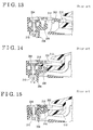
- a nut 204 is provided at a front end portion of a frame 202 and a rattle stopper 208 having an engaging jaw 206 is temporarily jointed by way of a screw bolt 210 .
- a handle axial portion 214 located at a front end portion of a handle main body 212 is engaged with the engaging jaw 206 .
- a rattle of the handle main body 212 against the frame 202 which occurs in the longitudinal direction of the vehicle at the time of the assembly, is prevented by tightening the screw bolt 210 .
- This known method is significantly effective for preventing the rattle of the handle main body against the frame, which occurs in the longitudinal direction of the vehicle.
- the method requires three components, i.e. the unit, the rattle stopper, and the screw bolt, to prevent the rattle, thus weight of components, as well as component cost, increases.
- the assembling work requires a tightening tool and thus hindering workability.
- a door handle device for a vehicle includes a frame member adapted to be mounted to a door of the vehicle, a handle main body pivotally fitted with the frame member, an engaging arm formed at the handle main body and pivotally engaging with the frame member, a handle axial portion formed at the engaging arm and serving as a pivotal center of the handle main body, a bearing member pivotally supported by the frame member, and a holding portion formed at the bearing member for holding the handle axial portion, wherein the holding portion is shifted between a released position where the handle axial portion is engageable with or disengageable from the holding portion and a supported position where the handle axial portion is pivotally supported with a pivotal movement of the bearing member.
- FIG. 1 is a perspective view illustrating an overview of a door handle device for a vehicle according to the present invention
- FIG. 2 is a fragmentary view illustrating the door handle device for the vehicle viewed from an inner side of a vehicle cabin;
- FIG. 3 is a view illustrating the door handle device for the vehicle from an outer side of the vehicle cabin
- FIG. 4 is a view illustrating a position of the door handle device for the vehicle in a door for the vehicle;
- FIG. 5 is a plain view of a bearing member
- FIG. 6 is an elevation view of the bearing member
- FIG. 7 is a view illustrating a state in which a handle axial portion is assembled to the bearing member
- FIG. 8 is a view illustrating an assembling state of the bearing member and the handle axial portion at a released position
- FIG. 9 is a view illustrating an assembling state of the bearing member and the handle axial portion at a supported position
- FIG. 10 is a view illustrating the bearing member at the released position
- FIG. 11 is a view illustrating the bearing member at the supported position
- FIG. 12 is a plain view illustrating a bearing hole of a frame member
- FIG. 13 is a view illustrating a prior art
- FIG. 14 is a view illustrating the prior art.
- FIG. 15 is a view illustrating the prior art.
- FIG. 1 is a perspective view illustrating an entire structure of an handle main body, a frame member and a bearing member
- FIG. 2 is an enlarged view illustrating an assembling state of the frame member and the bearing member when viewed from an inner side of the vehicle cabin.
- a door handle device for a vehicle 6 is mounted to an outer panel 4 of a door of the vehicle 2 .
- the door handle device for the vehicle 6 is provided with a frame member 8 , a lever (counter weight) 10 , a grip type handle main body 12 and a coil spring 14 .
- the frame member 8 is fixed to the outer panel 4 from an inner side of the door of the vehicle 2 and the lever 10 is pivotably supported by the frame member 8 .
- the grip type handle main body 12 is tiltably supported by the frame member 8 from an outer side of the outer panel 4 and the coil spring 14 biases the lever 10 for pivotal movement.
- the frame member 8 extends in a longitudinal direction of the vehicle (horizontal direction viewed in FIG. 1 ) and is formed in an elongated shape. Insertion openings 16 and 18 are respectively formed at front and rear ends of the frame member 8 .
- a bearing hole 20 is formed at both upper and lower sides of the frame member 8 , respectively.
- the bearing holes 20 are located in the vicinity of the insertion opening 16 and serve as bearing means which support a bearing member 34 which will be described below.
- the bearing holes 20 are provided at end portions of the upper and lower sides of the frame member 8 facing each other.
- An engagement path 19 is formed in each bearing hole 20 and the engagement paths 19 open to an outer side of the vehicle cabin to allow supporting shafts 40 of the bearing member 34 , which will be described below, to engage with or disengage from the bearing holes 20 .
- a narrowing portion is provided in each engagement path 19 to form a stopper 21 .
- a plate shaped external supporting portion 23 is mounted in the longitudinal direction of the vehicle at the outer side of the vehicle cabin relative to a transverse direction of the vehicle (upper side viewed in FIGS. 9 and 11 ). The mounting position of the external supporting portion 23 corresponds to an intermediate position between the facing bearing holes 20 .
- a supporting portion 22 and a holding portion 26 are integrally formed with the frame member 8 so as to be located in the vicinity of the insertion opening 18 .
- the supporting portion 22 supports the lever 10 and the holding portion 26 holds the coil spring 14 .
- the handle main body 12 extends in the longitudinal direction of the vehicle and is formed in an elongated shape. As illustrated in FIG. 1 , in a front end of the handle main body 12 (left side viewed in FIG. 1 ), an engaging arm 30 protrudes toward the inner side of the vehicle cabin to be inserted into the insertion opening 16 . A handle axial portion 28 is protruded in a pivotal (vertical) direction of the engaging arm 30 at a distal end of the engaging arm 30 , and the handle axial portion 28 is tiltably engaged with the frame member 8 via the bearing member 34 which will be described later.
- an engaging leg 32 is formed so as to protrude toward the inner side of the vehicle cabin.
- the engaging leg 32 is inserted into the insertion opening 18 and engages with an input portion 11 of the lever 10 .
- the lever 10 is biased by the coil spring 14 in a direction that the engaging leg 32 is drawn into the inner side (inner side of the vehicle cabin) of the outer panel 4 .
- the other end of the lever 10 is connected to a door lock (not shown) via a connecting rod (not shown).
- the bearing member 34 journals and assembles the handle axial portion 28 of the handle main body 12 to the frame member 8 so as to be pivotable.
- the bearing member 34 includes shaft holding portions 36 and the supporting shafts 40 .
- the shaft holding portions 36 are provided so as to sandwich the frame member 8 therebetween and face each other in the pivotal direction of the bearing member 34 .
- the supporting shaft 40 protrudes from each of the shaft holding portions 36 , which face each other, toward its axial inner side to be journaled by the bearing hole 20 .
- the bearing member 34 further includes holding portions 42 , a connecting frame 38 and operating arms 44 . As illustrated in FIGS.
- the holding portion 42 is provided at a distal end of each supporting shaft 40 , and each holding portion 42 opens to its inner side relative to an axial direction of the bearing member 34 and also opens to one direction which is perpendicular to the axial line.
- the connecting frame 38 is provided in parallel to the supporting shafts 40 and connects the facing shaft holding portions 36 to each other.
- Each operating arm 44 is provided continuously from the corresponding shaft holding portion 36 and protrudes perpendicular to the supporting shaft 40 .
- the operating arms 44 are connected to each other at facing distal ends thereof by a holding rod 43 , which extends in the pivotal direction of the bearing member.
- each holding portion 42 includes a pair of supporting side portions 46 and a supporting bottom portion 48 .
- the engaging arm 30 of the handle main body 12 is inserted between the facing holding portions 42 , and the handle axial portion 28 , which protrudes from the engaging arm 30 , is inserted into each opening of the holding portions 42 to be journaled.
- a holding surface of each holding portion 42 is structured of contacting surfaces of the supporting side portions 46 and the supporting bottom portion 48 , which contact with the handle axial portion 28 . Then, an axial center of the handle axial portion 28 journaled by the holding portions 42 and axial centers of the supporting shafts 40 are arranged concentrically. Also, as illustrated in FIG.
- clearances 50 are respectively provided at one of the supporting side portions 46 (one located in an upper side in FIG. 7 ) and the supporting bottom portion 48 along the contacting surfaces contacting with the handle axial portion 28 to form elastically deforming portions 52 .
- the clearances 50 are compressed in the elastically deforming portions 52 .
- the handle axial portion 28 moves from the rear side relative to the holding portions 42 to be engageable with or disengageable from the holding portions 42 .
- the position of the holding portions 42 is a released position.
- a pivotal end restricting portion (not shown), which restricts one pivotal end of the bearing member 34 , is provided at the frame member 8 .
- a protruding stopper 54 is provided at end portions of both side surfaces of the frame member 8 , and each protruding stopper 54 contacts with an edge of a proximal portion of the corresponding operating arm 44 . Specifically, the edges are located at the side of a pivoting direction. The contact stops the free pivotal movements of the operating arms 44 and holds the bearing member 34 at the released position.
- the openings of the holding portions 42 are positioned to face the outer side of the vehicle cabin relative to the transverse direction of the vehicle (upper side viewed in FIGS. 9 and 11 ), the openings of the holding portions 42 are automatically positioned to face the external supporting portion 23 of the frame member 8 .
- the handle axial portion 28 engaged with the holding portions 42 is supported between the external supporting portion 23 and the supporting bottom portion 48 in the transverse direction of the vehicle (vertical direction viewed in FIGS. 9 and 11 ).
- the handle axial portion 28 is supported between the pair of the supporting side portions 46 in the longitudinal direction of the vehicle (horizontal direction viewed in FIGS. 9 and 11 ).
- the handle axial portion 28 is pivotally journaled.
- the position of the holding portions 42 under the above condition is a supported position.
- the connecting frame 38 contacts with the front end of the frame member 8 and the holding rod 43 contacts with an end surface of the frame member 8 located at the inner side of the vehicle cabin. These contacts restrict the other pivotal end of the bearing member 34 , thereby forming another pivotal end restricting portion.
- an engaging portion 58 in which an engaging hole 56 is formed, is provided at a side surface of a distal end of each operating arm 44 .
- the engaging holes 56 engage with a pair of engaging protrusions 60 provided at upper and lower side surfaces of the frame member 8 .
- the engagement restricts the free pivotal movement of the operating arm 44 to hold the bearing member 34 at the supported position.
- the holding rod 43 of the operating arms 44 is formed protruding parallel with the pivotal (vertical) direction of the bearing member 34 to form holding protrusions.
- the bearing member 34 is assembled to the frame member 8 .
- the engaging path 19 is provided at each bearing hole 20 of the frame member 8 , and thus it is possible to engage each supporting shaft 40 with the corresponding bearing hole 20 easily by inserting the supporting shaft 40 of the bearing member 34 into the bearing hole 20 along the engagement path 19 .
- the stopper 21 is provided at the engagement path 19 and the stopper 21 prevents the supporting shaft 40 from falling off the bearing hole 20 once the supporting shaft 40 is engaged with the bearing hole 20 .
- the engaging arm 30 and the engaging leg 32 are inserted from the insertion openings 16 and 18 of the frame member 8 , respectively.
- the bearing member 34 is pivoted to the released position by operating the operating arms 44 and is held at the released position by way of the protruding stopper 54 and the like.
- the handle axial portion 28 of the engaging arm 30 is inserted into the holding portions 42 of the bearing member 34 to be journaled.
- the bearing member 34 is positioned so that the openings of the holding portions 42 face to the rear side of the vehicle (right side viewed in FIGS.
- the handle axial portion 28 is moved from the rear side of the vehicle to engage with the bearing member 34 easily.
- the engage leg 32 is engaged with the input portion 11 of the lever 10 to bias the lever 10 in a direction that the engaging leg 32 is drawn into the inner side (inner side of the vehicle cabin) of the outer panel 4 .
- the bearing member 34 is pivoted to the supported position by operating the operating arms 44 .
- the operating arms 44 pass over the protruding stoppers 54 to pivot.
- the openings of the holding portions 42 of the bearing member 34 are positioned to face the outer side of the vehicle cabin relative to the transverse direction of the vehicle (upper side viewed in FIG. 9 ).
- the openings of the holding portions 42 face the external supporting portion 23 of the frame member 8 . Therefore, the handle axial portion 28 is supported at its both sides by the external supporting portion 23 and the supporting bottom portion 48 in the transverse direction of the vehicle (vertical direction viewed in FIG.
- the handle main body 12 pivots with the handle axial portion 28 serving as a pivotal center without causing the rattle against the frame member 8 in the transverse and longitudinal directions of the vehicle.
- the elastically deforming portions 52 which are provided at the supporting side portion 46 and the supporting bottom portion 48 , are pressed by the handle axial portion 28 to be bent.
- the deflection absorbs manufacturing variations between the outer circumference size of the handle axial portion 28 and the size of the space defined between the pair of the supporting side portions 46 and also absorbs manufacturing variations between the outer circumference size of the handle axial portion 28 and the size of the space defined between the external supporting portion 23 and the supporting bottom portion 48 .
- the bearing holes 20 are provided at the frame member 8 and the supporting shafts 40 , each journaled by the corresponding bearing holes 20 , are provided at the bearing member 34 .
- the configuration is not limited to this form, for example, supporting shafts may be provided at the frame member and the bearing holes may be provided at the bearing member.
- the engaging arm 30 of the handle main body 12 (handle axial portion 28 ) is disposed at the front side relative to the longitudinal direction of the vehicle, however, the configuration is not limited to this form. The engaging arm may be disposed at the rear side relative to the longitudinal direction of the vehicle depending on the structure of the door of the vehicle.
- the holding rod 43 protrudes parallel with the pivotal direction of the bearing member 34 .
- the form of the holding rod is not limited to this.
- the holding rod does not have to protrude more than width of the operating arm.
- the holding rod may protrude in one direction.
- the handle axial portion 28 is engaged with the holding portions 42 when the bearing member 34 is positioned at the released position. Then, the bearing member 34 is pivoted relative to the frame member 8 to be positioned at the supported position. In the supported position, the handle axial portion 28 is pivotally supported by the holding portions 42 .
- operating arms 44 are formed at the bearing member 34 , and the operating arms 44 protrude in a perpendicular direction to a center of a pivotal axis.
- Each operating arm 44 is formed with a holding protrusion protruding in at least one of upward and downward directions of the bearing member and being held for pivoting the operating arm 44 .
- the bearing member 34 when the bearing member 34 is pivoted by the operation of the operating arms 44 , which protrude in a perpendicular direction from a center of the pivotal axis, the operating arms 44 are held by the operator. Thus, the bearing member 34 is pivoted with a very small force. Further, when the handle main body 12 is detached from the frame member 8 for maintenance purpose and the like, the holding protrusions are held by the operator to separate the components. Thus, it is possible to pivot the bearing member 34 from the supported position to the released position easily by operating the operating arm 44 .
- a door handle device for a vehicle 6 includes supporting shafts 40 provided at the bearing member 34 and protruding in a pivotal direction of the bearing member 34 , and bearing holes 20 provided at the frame member 8 for pivotally journaling the supporting shafts 40 .
- Each bearing hole 20 is provided with an engagement path 19 formed for engaging with or disengaging from the supporting shaft 40 in a perpendicular direction to a center of a pivotal axis and a stopper preventing the supporting shaft 40 from falling off the engagement path 19 .
- the engagement path 19 is provided at each bearing hole 20 of the frame member 8 .
- each supporting shaft 40 of the bearing member 34 is assembled to or removed from the bearing hole 20 easily.
- the stopper 21 is provided at each engagement path 19 .
- the holding portion 42 is formed with a holding surface 46 , 48 holding the handle axial portion 28 and an elastically deforming portion 52 is included in the holding surface 46 , 48 .
- the elastically deforming portion 52 is pressed and bent when the handle axial portion 28 is held.
- the elastically deforming portions 52 are pressed and bent by the handle axial portion 28 .
Landscapes
- Lock And Its Accessories (AREA)
Priority Applications (1)
| Application Number | Priority Date | Filing Date | Title |
|---|---|---|---|
| US12/893,303 US8157301B2 (en) | 2006-08-25 | 2010-09-29 | Door handle device for vehicle |
Applications Claiming Priority (2)
| Application Number | Priority Date | Filing Date | Title |
|---|---|---|---|
| JP2006-229155 | 2006-08-25 | ||
| JP2006229155A JP4835324B2 (ja) | 2006-08-25 | 2006-08-25 | 車両用ドアハンドル装置 |
Related Child Applications (1)
| Application Number | Title | Priority Date | Filing Date |
|---|---|---|---|
| US12/893,303 Division US8157301B2 (en) | 2006-08-25 | 2010-09-29 | Door handle device for vehicle |
Publications (2)
| Publication Number | Publication Date |
|---|---|
| US20080047203A1 US20080047203A1 (en) | 2008-02-28 |
| US7827736B2 true US7827736B2 (en) | 2010-11-09 |
Family
ID=38566780
Family Applications (2)
| Application Number | Title | Priority Date | Filing Date |
|---|---|---|---|
| US11/834,029 Active 2029-05-15 US7827736B2 (en) | 2006-08-25 | 2007-08-06 | Door handle device for vehicle |
| US12/893,303 Active US8157301B2 (en) | 2006-08-25 | 2010-09-29 | Door handle device for vehicle |
Family Applications After (1)
| Application Number | Title | Priority Date | Filing Date |
|---|---|---|---|
| US12/893,303 Active US8157301B2 (en) | 2006-08-25 | 2010-09-29 | Door handle device for vehicle |
Country Status (4)
| Country | Link |
|---|---|
| US (2) | US7827736B2 (de) |
| EP (1) | EP1895080B1 (de) |
| JP (1) | JP4835324B2 (de) |
| CN (2) | CN102926585B (de) |
Cited By (9)
| Publication number | Priority date | Publication date | Assignee | Title |
|---|---|---|---|---|
| US20080088139A1 (en) * | 2004-07-23 | 2008-04-17 | Aisin Seiki Kabushiki Kaisha | Door Handle Device for Vehicle |
| US20100171327A1 (en) * | 2007-06-13 | 2010-07-08 | Huls Hulsbeck & Furst Gmbh & Co. Kg | Device for actuating the closure of a movable part |
| US20110016670A1 (en) * | 2006-08-25 | 2011-01-27 | Aisin Seiki Kabushiki Kaisha | Door handle device for vehicle |
| US20110042973A1 (en) * | 2009-08-18 | 2011-02-24 | Aisin Seiki Kabushiki Kaisha | Door handle apparatus for vehicle |
| US20120104774A1 (en) * | 2010-11-03 | 2012-05-03 | Hyundai Motor Company | Outside handle assembly of vehicle |
| US20130193697A1 (en) * | 2009-12-28 | 2013-08-01 | Cnh Amercia Llc | Vehicle body panel latch with remote actuator |
| US8777281B2 (en) | 2009-08-19 | 2014-07-15 | Kabushiki Kaisha Honda Lock | Outside handle device for vehicle door |
| US10267072B2 (en) * | 2014-07-30 | 2019-04-23 | Aisin Seiki Kabushiki Kaisha | Door handle apparatus for vehicle |
| US11788324B2 (en) * | 2018-12-14 | 2023-10-17 | Kabushiki Kaisha Honda Lock | Outer handle device for vehicle door |
Families Citing this family (13)
| Publication number | Priority date | Publication date | Assignee | Title |
|---|---|---|---|---|
| JP5380178B2 (ja) * | 2009-06-25 | 2014-01-08 | 株式会社ユーシン | 車両用ドアハンドル装置 |
| DE102009056921A1 (de) * | 2009-12-03 | 2011-06-09 | GM Global Technology Operations LLC, ( n. d. Ges. d. Staates Delaware ), Detroit | Griffmodul für eine Kraftfahrzeugtür |
| JP2012092636A (ja) * | 2010-09-30 | 2012-05-17 | Aisin Seiki Co Ltd | 車両用ドアハンドル装置 |
| DE102010038065A1 (de) * | 2010-10-08 | 2012-04-12 | Huf Hülsbeck & Fürst Gmbh & Co. Kg | Türaußengriffvorrichtung |
| WO2013109306A2 (en) * | 2011-06-20 | 2013-07-25 | Adac Plastics, Inc. | Door handle assembly, sub-assembly and method of installing same |
| US10024085B2 (en) | 2012-07-13 | 2018-07-17 | Trimark Corporation | Compression mount paddle handle |
| DE102012020265B3 (de) * | 2012-10-12 | 2013-11-28 | Audi Ag | Türaußengriffanordnung für eine Fahrzeugtüre eines Fahrzeugs |
| US9605451B2 (en) | 2013-03-14 | 2017-03-28 | Ford Global Technologies, Llc | Wobble free exterior handle design |
| DE102014003931B3 (de) * | 2014-03-18 | 2015-09-24 | Dürr Systems GmbH | Roboteranordnung mit paarweise aneinander angepasstem Applikationsgerät mit Zwischenflansch und entsprechendes Montageverfahren |
| JP7178267B2 (ja) * | 2019-01-15 | 2022-11-25 | サカエ理研工業株式会社 | 車両用ドアハンドル装置 |
| KR102852060B1 (ko) | 2020-01-09 | 2025-08-27 | 삼성중공업 주식회사 | 계류용 파일의 지지 장치 |
| CN112282527B (zh) * | 2020-11-24 | 2025-09-05 | 浙江春风动力股份有限公司 | 一种边门开启机构 |
| JP7770117B2 (ja) * | 2021-06-04 | 2025-11-14 | 株式会社アルファ | 車両用ドアハンドル装置 |
Citations (4)
| Publication number | Priority date | Publication date | Assignee | Title |
|---|---|---|---|---|
| JP2002004649A (ja) | 2000-06-21 | 2002-01-09 | Aisin Seiki Co Ltd | 車両用ドアハンドル装置 |
| US6363577B1 (en) * | 2000-08-25 | 2002-04-02 | Adac Plastics, Inc. | Motor vehicle door handle assembly with maximized bearing interface |
| US20020089194A1 (en) * | 2001-01-11 | 2002-07-11 | Morihito Nomura | Vehicle door handle device |
| US6910303B1 (en) * | 1999-10-05 | 2005-06-28 | Huf Hülsbeck & Fürst Gmbh & Co. Kg | Device for actuating an electronic locking system and/or a lock integrated in a door, a flap or the like, especially in a motor vehicle |
Family Cites Families (9)
| Publication number | Priority date | Publication date | Assignee | Title |
|---|---|---|---|---|
| GB0006932D0 (en) * | 2000-03-23 | 2000-05-10 | Meritor Light Vehicle Sys Ltd | Latch mechanism |
| GB0321909D0 (en) * | 2003-09-19 | 2003-10-22 | Arvinmeritor Light Vehicle Sys | Latch bolt |
| JP4536580B2 (ja) * | 2004-05-13 | 2010-09-01 | 株式会社ニフコ | 自動車のドアハンドル装置 |
| US7971913B2 (en) * | 2004-07-23 | 2011-07-05 | Aisin Seiki Kabushiki Kaisha | Door handle device for vehicle |
| JP4469241B2 (ja) * | 2004-07-23 | 2010-05-26 | アイシン精機株式会社 | 車両用ドアハンドル装置 |
| JP4569403B2 (ja) * | 2005-06-27 | 2010-10-27 | アイシン精機株式会社 | 車両用ドアハンドル装置 |
| US7344168B2 (en) * | 2004-10-14 | 2008-03-18 | U-Shin Ltd. | Door handle device for vehicles |
| JP4835324B2 (ja) * | 2006-08-25 | 2011-12-14 | アイシン精機株式会社 | 車両用ドアハンドル装置 |
| JP5407652B2 (ja) * | 2009-08-18 | 2014-02-05 | アイシン精機株式会社 | 車両用ドアハンドル装置 |
-
2006
- 2006-08-25 JP JP2006229155A patent/JP4835324B2/ja active Active
-
2007
- 2007-08-06 US US11/834,029 patent/US7827736B2/en active Active
- 2007-08-14 EP EP20070114299 patent/EP1895080B1/de active Active
- 2007-08-23 CN CN201210395258.7A patent/CN102926585B/zh active Active
- 2007-08-23 CN CN2007101461221A patent/CN101131050B/zh active Active
-
2010
- 2010-09-29 US US12/893,303 patent/US8157301B2/en active Active
Patent Citations (5)
| Publication number | Priority date | Publication date | Assignee | Title |
|---|---|---|---|---|
| US6910303B1 (en) * | 1999-10-05 | 2005-06-28 | Huf Hülsbeck & Fürst Gmbh & Co. Kg | Device for actuating an electronic locking system and/or a lock integrated in a door, a flap or the like, especially in a motor vehicle |
| JP2002004649A (ja) | 2000-06-21 | 2002-01-09 | Aisin Seiki Co Ltd | 車両用ドアハンドル装置 |
| US6363577B1 (en) * | 2000-08-25 | 2002-04-02 | Adac Plastics, Inc. | Motor vehicle door handle assembly with maximized bearing interface |
| US20020089194A1 (en) * | 2001-01-11 | 2002-07-11 | Morihito Nomura | Vehicle door handle device |
| US6964439B2 (en) * | 2001-01-11 | 2005-11-15 | Aisin Seiki Kabushiki Kaisha | Vehicle door handle device |
Cited By (14)
| Publication number | Priority date | Publication date | Assignee | Title |
|---|---|---|---|---|
| US20080088139A1 (en) * | 2004-07-23 | 2008-04-17 | Aisin Seiki Kabushiki Kaisha | Door Handle Device for Vehicle |
| US7971913B2 (en) * | 2004-07-23 | 2011-07-05 | Aisin Seiki Kabushiki Kaisha | Door handle device for vehicle |
| US20110016670A1 (en) * | 2006-08-25 | 2011-01-27 | Aisin Seiki Kabushiki Kaisha | Door handle device for vehicle |
| US8157301B2 (en) * | 2006-08-25 | 2012-04-17 | Aisin Seiki Kabushiki Kaisha | Door handle device for vehicle |
| US20100171327A1 (en) * | 2007-06-13 | 2010-07-08 | Huls Hulsbeck & Furst Gmbh & Co. Kg | Device for actuating the closure of a movable part |
| US8864191B2 (en) * | 2007-06-13 | 2014-10-21 | Huf Hulsbeck & Furst Gmbh & Co. Kg | Device for actuating the closure of a movable part |
| US20110042973A1 (en) * | 2009-08-18 | 2011-02-24 | Aisin Seiki Kabushiki Kaisha | Door handle apparatus for vehicle |
| US8459706B2 (en) * | 2009-08-18 | 2013-06-11 | Aisin Seiki Kabushiki Kaisha | Door handle apparatus for vehicle |
| US8777281B2 (en) | 2009-08-19 | 2014-07-15 | Kabushiki Kaisha Honda Lock | Outside handle device for vehicle door |
| US20130193697A1 (en) * | 2009-12-28 | 2013-08-01 | Cnh Amercia Llc | Vehicle body panel latch with remote actuator |
| US8783743B2 (en) * | 2010-11-03 | 2014-07-22 | Hyundai Motor Company | Outside handle assembly of vehicle |
| US20120104774A1 (en) * | 2010-11-03 | 2012-05-03 | Hyundai Motor Company | Outside handle assembly of vehicle |
| US10267072B2 (en) * | 2014-07-30 | 2019-04-23 | Aisin Seiki Kabushiki Kaisha | Door handle apparatus for vehicle |
| US11788324B2 (en) * | 2018-12-14 | 2023-10-17 | Kabushiki Kaisha Honda Lock | Outer handle device for vehicle door |
Also Published As
| Publication number | Publication date |
|---|---|
| EP1895080A2 (de) | 2008-03-05 |
| US8157301B2 (en) | 2012-04-17 |
| CN102926585B (zh) | 2015-04-22 |
| CN102926585A (zh) | 2013-02-13 |
| JP2008050870A (ja) | 2008-03-06 |
| CN101131050B (zh) | 2012-11-28 |
| EP1895080A3 (de) | 2013-03-06 |
| CN101131050A (zh) | 2008-02-27 |
| EP1895080B1 (de) | 2014-04-02 |
| US20080047203A1 (en) | 2008-02-28 |
| JP4835324B2 (ja) | 2011-12-14 |
| US20110016670A1 (en) | 2011-01-27 |
Similar Documents
| Publication | Publication Date | Title |
|---|---|---|
| US7827736B2 (en) | Door handle device for vehicle | |
| US7665791B2 (en) | Seat slide device for vehicle | |
| US6749236B2 (en) | Door handle device for a vehicle | |
| US9181734B2 (en) | Vehicle door handle device | |
| US8322077B2 (en) | Vehicle door handle with inertia lock mechanism | |
| US7478846B2 (en) | Door lock device and assembling method thereof | |
| US7357436B2 (en) | Latch mechanism for automotive seat assembly | |
| US20230256872A1 (en) | Seat Sliding Device | |
| US20090033138A1 (en) | Lock apparatus of seat for vehicle | |
| CN113840969A (zh) | 配件装置 | |
| US8777281B2 (en) | Outside handle device for vehicle door | |
| CN110226016B (zh) | 车门的外把手装置 | |
| US11872912B2 (en) | Seat sliding device | |
| US20200190867A1 (en) | Outer handle device for vehicle door | |
| JP2009514125A (ja) | ヒステリシス機構を有するペダル | |
| US6802544B1 (en) | Vehicle door handle | |
| US20240100999A1 (en) | Seat Sliding Device | |
| US9181733B2 (en) | Vehicle door handle system | |
| US20110006551A1 (en) | Latch assembly and detent lever thereof | |
| JP4060466B2 (ja) | 操作機構 | |
| JP7127246B2 (ja) | 車両ラッチ装置の組付方法 | |
| CN104769198A (zh) | 车辆用门锁装置 | |
| JP2002097827A (ja) | ロック装置 | |
| JP2004332432A (ja) | 車両用ドアハンドル装置 | |
| JPH0546964Y2 (de) |
Legal Events
| Date | Code | Title | Description |
|---|---|---|---|
| AS | Assignment |
Owner name: AISIN SEIKI KABUSHIKI KAISHA, JAPAN Free format text: ASSIGNMENT OF ASSIGNORS INTEREST;ASSIGNORS:SUNAHARA, SHIGEYUKI;NOMURA, MORIHITO;NAGATA, KOICHI;REEL/FRAME:019647/0858;SIGNING DATES FROM 20070726 TO 20070727 |
|
| STCF | Information on status: patent grant |
Free format text: PATENTED CASE |
|
| FEPP | Fee payment procedure |
Free format text: PAYOR NUMBER ASSIGNED (ORIGINAL EVENT CODE: ASPN); ENTITY STATUS OF PATENT OWNER: LARGE ENTITY |
|
| FPAY | Fee payment |
Year of fee payment: 4 |
|
| MAFP | Maintenance fee payment |
Free format text: PAYMENT OF MAINTENANCE FEE, 8TH YEAR, LARGE ENTITY (ORIGINAL EVENT CODE: M1552) Year of fee payment: 8 |
|
| MAFP | Maintenance fee payment |
Free format text: PAYMENT OF MAINTENANCE FEE, 12TH YEAR, LARGE ENTITY (ORIGINAL EVENT CODE: M1553); ENTITY STATUS OF PATENT OWNER: LARGE ENTITY Year of fee payment: 12 |