US7856916B2 - Isolation systems, inertial navigation systems, and recoil artillery systems - Google Patents
Isolation systems, inertial navigation systems, and recoil artillery systems Download PDFInfo
- Publication number
- US7856916B2 US7856916B2 US12/173,568 US17356808A US7856916B2 US 7856916 B2 US7856916 B2 US 7856916B2 US 17356808 A US17356808 A US 17356808A US 7856916 B2 US7856916 B2 US 7856916B2
- Authority
- US
- United States
- Prior art keywords
- sidewall
- elastomeric isolator
- inner sidewall
- outer sidewall
- single axis
- Prior art date
- Legal status (The legal status is an assumption and is not a legal conclusion. Google has not performed a legal analysis and makes no representation as to the accuracy of the status listed.)
- Active, expires
Links
- 238000002955 isolation Methods 0.000 title claims abstract description 37
- 238000010304 firing Methods 0.000 claims abstract description 17
- 230000035939 shock Effects 0.000 claims description 11
- 239000006096 absorbing agent Substances 0.000 claims description 8
- 238000013016 damping Methods 0.000 claims description 8
- 230000008878 coupling Effects 0.000 claims description 3
- 238000010168 coupling process Methods 0.000 claims description 3
- 238000005859 coupling reaction Methods 0.000 claims description 3
- 230000001133 acceleration Effects 0.000 description 10
- 239000000463 material Substances 0.000 description 9
- 238000005259 measurement Methods 0.000 description 5
- 239000013536 elastomeric material Substances 0.000 description 3
- 229910000831 Steel Inorganic materials 0.000 description 2
- 229910045601 alloy Inorganic materials 0.000 description 2
- 239000000956 alloy Substances 0.000 description 2
- 229910052782 aluminium Inorganic materials 0.000 description 2
- XAGFODPZIPBFFR-UHFFFAOYSA-N aluminium Chemical compound [Al] XAGFODPZIPBFFR-UHFFFAOYSA-N 0.000 description 2
- 229910010293 ceramic material Inorganic materials 0.000 description 2
- 230000008859 change Effects 0.000 description 2
- 230000003247 decreasing effect Effects 0.000 description 2
- 238000006073 displacement reaction Methods 0.000 description 2
- 239000012530 fluid Substances 0.000 description 2
- 239000007789 gas Substances 0.000 description 2
- 230000007246 mechanism Effects 0.000 description 2
- 229910052751 metal Inorganic materials 0.000 description 2
- 239000002184 metal Substances 0.000 description 2
- 239000007769 metal material Substances 0.000 description 2
- 239000010959 steel Substances 0.000 description 2
- 229910000838 Al alloy Inorganic materials 0.000 description 1
- 244000043261 Hevea brasiliensis Species 0.000 description 1
- 230000000712 assembly Effects 0.000 description 1
- 238000000429 assembly Methods 0.000 description 1
- 230000004323 axial length Effects 0.000 description 1
- 229920001971 elastomer Polymers 0.000 description 1
- 230000002452 interceptive effect Effects 0.000 description 1
- 229920003052 natural elastomer Polymers 0.000 description 1
- 229920001194 natural rubber Polymers 0.000 description 1
- 229920001296 polysiloxane Polymers 0.000 description 1
- 230000004044 response Effects 0.000 description 1
- 229920002379 silicone rubber Polymers 0.000 description 1
- 239000004945 silicone rubber Substances 0.000 description 1
- 230000008685 targeting Effects 0.000 description 1
Images




Classifications
-
- F—MECHANICAL ENGINEERING; LIGHTING; HEATING; WEAPONS; BLASTING
- F41—WEAPONS
- F41G—WEAPON SIGHTS; AIMING
- F41G1/00—Sighting devices
- F41G1/38—Telescopic sights specially adapted for smallarms or ordnance; Supports or mountings therefor
- F41G1/393—Mounting telescopic sights on ordnance; Transmission of sight movements to the associated gun
-
- F—MECHANICAL ENGINEERING; LIGHTING; HEATING; WEAPONS; BLASTING
- F41—WEAPONS
- F41G—WEAPON SIGHTS; AIMING
- F41G1/00—Sighting devices
- F41G1/40—Periscopic sights specially adapted for smallarms or ordnance; Supports or mountings therefor
-
- F—MECHANICAL ENGINEERING; LIGHTING; HEATING; WEAPONS; BLASTING
- F41—WEAPONS
- F41G—WEAPON SIGHTS; AIMING
- F41G11/00—Details of sighting or aiming apparatus; Accessories
-
- F—MECHANICAL ENGINEERING; LIGHTING; HEATING; WEAPONS; BLASTING
- F41—WEAPONS
- F41G—WEAPON SIGHTS; AIMING
- F41G3/00—Aiming or laying means
- F41G3/32—Devices for testing or checking
- F41G3/323—Devices for testing or checking for checking the angle between the muzzle axis of the gun and a reference axis, e.g. the axis of the associated sighting device
-
- F—MECHANICAL ENGINEERING; LIGHTING; HEATING; WEAPONS; BLASTING
- F41—WEAPONS
- F41G—WEAPON SIGHTS; AIMING
- F41G5/00—Elevating or traversing control systems for guns
- F41G5/26—Apparatus for testing or checking
-
- Y—GENERAL TAGGING OF NEW TECHNOLOGICAL DEVELOPMENTS; GENERAL TAGGING OF CROSS-SECTIONAL TECHNOLOGIES SPANNING OVER SEVERAL SECTIONS OF THE IPC; TECHNICAL SUBJECTS COVERED BY FORMER USPC CROSS-REFERENCE ART COLLECTIONS [XRACs] AND DIGESTS
- Y10—TECHNICAL SUBJECTS COVERED BY FORMER USPC
- Y10S—TECHNICAL SUBJECTS COVERED BY FORMER USPC CROSS-REFERENCE ART COLLECTIONS [XRACs] AND DIGESTS
- Y10S248/00—Supports
- Y10S248/90—Movable or disengageable on impact or overload
-
- Y—GENERAL TAGGING OF NEW TECHNOLOGICAL DEVELOPMENTS; GENERAL TAGGING OF CROSS-SECTIONAL TECHNOLOGIES SPANNING OVER SEVERAL SECTIONS OF THE IPC; TECHNICAL SUBJECTS COVERED BY FORMER USPC CROSS-REFERENCE ART COLLECTIONS [XRACs] AND DIGESTS
- Y10—TECHNICAL SUBJECTS COVERED BY FORMER USPC
- Y10S—TECHNICAL SUBJECTS COVERED BY FORMER USPC CROSS-REFERENCE ART COLLECTIONS [XRACs] AND DIGESTS
- Y10S248/00—Supports
- Y10S248/916—Mechanical expedients, e.g. in supports
Definitions
- the inventive subject matter generally relates to recoil artillery systems, and more particularly relates to isolation and inertial navigation systems that may be included in recoil artillery systems.
- IMU Inertial measurement units
- an IMU includes electronics devices, such as gyroscopes and accelerometers.
- the electronics devices sense real-time rotational and acceleration data that are compared to reference data stored in the IMU. The compared data is then used to calculate a current position of the moving object.
- IMUs operate virtually independently from other devices after receiving the reference data, they have been considered for implementation onto towed artillery systems. Specifically, IMUs have been investigated as devices for improving targeting accuracy of guided projectiles fired from the artillery systems. However, several obstacles have been encountered. For example, one or more IMUs are typically included as part of an inertial sensor assembly (“ISA”) that is mounted in a chassis along with additional electronics. The ISA, and hence, the IMU, comprise part of an inertial navigation system (INS), which may be coupled directly to a platform on the towed artillery system. When one or more rounds of projectiles are fired from a barrel of the system, the INS, and hence, the IMU, experience a very high shock (e.g., greater than 40 G). The very high shock may cause the electronics devices within the INS to decouple from the chassis and to have a significantly decreased useful life.
- ISA inertial sensor assembly
- INS inertial navigation system
- elastomeric isolators have been included between the chassis and the platform. Although displacement of the ISA relative to the platform is decreased by the elastomeric dampers, the ISA may still experience an undesirable magnitude of acceleration in response to the very high shock. In particular, the ISA and the platform may resonate in phase to thereby amplify an acceleration input into the system. Additionally, in instances in which the barrel may undergo rapid firing sequences, positioning of the INS, and hence, the IMU, relative to the system platform may change between shots, and the elastomeric isolators may not be capable of minimizing the positional changes (i.e., improved repeatability). As a result, the positional changes may affect the operability and pointing accuracy of the INS.
- Isolation systems and recoil artillery systems are provided.
- an isolation system for mounting an inertial navigation system onto an artillery system having a barrel, the barrel adapted to move along a longitudinal axis during a firing sequence.
- the system includes an inner cradle, an outer cradle, first and second elastomeric isolators, and a first single axis damper.
- the inner cradle has a base plate, a first inner sidewall, and a second inner sidewall.
- the base plate is adapted to receive the inertial navigation system thereon, the first inner sidewall and the second inner sidewall are positioned opposite from each other, and the base plate extends therebetween.
- the outer cradle surrounds the inner cradle and includes a platform, a first outer sidewall, and a second outer sidewall.
- the first outer sidewall and the second outer sidewall are positioned opposite from each other, and the platform extends therebetween.
- the first elastomeric isolator is mounted between the first inner sidewall and the first outer sidewall.
- the second elastomeric isolator is mounted between the first inner sidewall and the first outer sidewall.
- the first single axis damper is aligned substantially parallel with the longitudinal axis and includes a first end and a second end, the first end is mounted to the first inner sidewall, and the second end is mounted to the first outer sidewall.
- a recoil artillery system having a barrel adapted to move along a longitudinal axis during a firing sequence.
- the recoil artillery system includes an inertial navigation system, an inner cradle, an outer cradle, elastomeric isolators, and single axis dampers.
- the inner cradle has a base plate, a first inner sidewall, and a second inner sidewall.
- the base plate includes the inertial navigation system thereon, and the first inner sidewall and the second inner sidewall are positioned opposite from each other and include the base plate therebetween.
- the outer cradle surrounds the inner cradle and includes a platform, a first outer sidewall, and a second outer sidewall.
- the first outer sidewall and the second outer sidewall are positioned opposite from each other and include the platform therebetween.
- First and second elastomeric isolators are mounted between the first inner sidewall and the first outer sidewall, and a third and a fourth elastomeric isolators are mounted between the second inner sidewall and the second outer sidewall.
- a first single axis damper is aligned substantially parallel with the longitudinal axis and including a first end and a second end, where the first end is mounted to the first inner sidewall and the second end is mounted to the first outer sidewall.
- the second single axis damper includes a first end and a second end, the first end is mounted to the second inner sidewall, and the second end is mounted to the second outer sidewall.
- the recoil artillery system includes a barrel adapted to travel along a longitudinal axis during a firing sequence, an inertial navigation system adapted to aim the barrel at a desired location, and an isolation damping system coupling the barrel and the inertial navigation system.
- the isolation damping system includes an inner cradle having a base plate, a first inner sidewall, and a second inner sidewall, the base plate including the inertial navigation system thereon, the first inner sidewall and the second inner sidewall positioned opposite from each other and including the base plate therebetween, an outer cradle surrounding the inner cradle and including a platform, a first outer sidewall, and a second outer sidewall, the first outer sidewall and the second outer sidewall positioned opposite from each other and including the platform therebetween, a first elastomeric isolator mounted between the first inner sidewall and the first outer sidewall, a second elastomeric isolator mounted between the first inner sidewall and the first outer sidewall, and a first single axis damper aligned substantially parallel with the longitudinal axis and including a first end and a second end, the first end mounted to the first inner sidewall, and the second end mounted to the first outer sidewall.
- FIG. 1 is a perspective view of a portion of a recoil artillery system, according to an embodiment
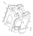
- FIG. 2 is a perspective view of an interior portion of an inertial navigation system (“INS”), according to an embodiment
- FIG. 3 is an isometric view of a secondary isolation system including an INS disposed therein, according to an embodiment
- FIG. 4 is an isometric view of the secondary isolation system of FIG. 3 without the INS disposed therein, according to an embodiment
- FIG. 5 is an isometric view of a shock absorber, according to an embodiment.
- FIG. 1 is a perspective view of a portion of a recoil artillery system 100 , according to an embodiment.
- the recoil artillery system 100 may be a towed artillery system that may be moved to a desired location and used to fire one or more projectiles at a desired target.
- the recoil artillery system 100 may include a gun tube or barrel 102 adapted to travel along a longitudinal axis 104 during a firing sequence.
- the barrel 102 may be mounted to a movable base 108 , which may be towed from location to location.
- the movable base 108 may include a chassis 110 and an assembly for repositioning the chassis 110 relative to the desired target.
- the assembly may include two or more wheels (not shown) rotatably attached to the chassis 110 .
- the assembly may include a different feature suitable for repositioning the chassis 110 , such a hover feature, or sliding mechanism.
- various damping elements, such as isolators, and bearing assemblies may be coupled between the chassis 110 and the barrel 102 to allow the barrel 102 to recoil during the firing sequence.
- the recoil artillery system 100 may also include an inertial navigation system (INS) 116 that is surrounded by an external isolation system 118 .
- INS inertial navigation system
- the INS 116 may have a tendency to move along the longitudinal axis 104 .
- the external isolation system 118 is included.
- the external isolation system 118 couples the INS 116 to the barrel 102 via a collar 120 .
- FIG. 2 is a perspective view of an interior portion of an INS 200 , according to an embodiment.
- the INS 200 includes a containment housing 202 and an inertial sensor assembly (ISA) 204 disposed in the containment housing 202 .
- the containment housing 202 includes sidewalls 206 , 208 , 210 , 212 and end walls 214 , 216 that together form a chamber 218 .
- the containment housing 202 may have relatively small dimensions, such a width in a range of between about 20 cm to about 25 cm, a length in a range of between about 23 cm to about 27 cm, and a height in a range of between about 10 cm to about 15 cm. However, in other embodiments, the particular dimensions may be larger or smaller.
- the containment housing 202 is shown in FIG. 2 as being box-shaped, it may have any other shape suitable for disposal of ISA 204 .
- the containment housing 202 may be spherical, hemispherical, cube-shaped, or any other shape.
- the ISA 204 may be positioned within the chamber 218 and may be made up of one or more inertial measurement units (not shown).
- an inertial measurement unit for each axis of inertial motion may be included.
- three inertial measurement units capable of measuring inertial motion along each axes may be included.
- the inertial sensor assembly 204 may be suspended between the sidewalls 206 , 208 , 210 , 212 via one or more isolators 220 , 222 , 224 , 228 , 230 , 232 , 234 .
- the one or more isolators 220 , 222 , 224 , 228 , 230 , 232 , 234 act as a primary isolation system to limit the vibration that may be transmitted through the containment housing 202 to the ISA 204 .
- one or more of the isolators 220 , 222 , 224 , 228 , 230 , 232 , 234 may be elastomeric isolators that include a cup-shaped elastomeric member having pads for mounting to mount surfaces (e.g., sidewalls 206 , 208 ).
- mount surfaces e.g., sidewalls 206 , 208
- the elastomeric material includes, but is not limited to natural rubber or silicone rubber.
- the cup-shaped elastomeric material has an axial length in a range of between about 0.5 cm and about 1.0 cm and a widest diameter in a range of between about 2.0 cm to about 4.0 cm. In other embodiments, the dimensions are greater than or smaller than the aforementioned range.
- one or more of the isolators 220 , 22 , 224 , 228 , 230 , 232 , 234 may be other types of damping mechanisms, such as a viscous damper or wire rope isolator
- the isolators 220 , 222 , 224 , 228 , 230 , 232 , 234 may be positioned at particular locations within the chamber 218 to optimize isolation of vibration that may be experienced by the electronics 202 .
- a first set of isolators e.g., isolators 220 , 222 , 224 , 228
- a second set of isolators e.g., isolators 230 , 232 , 234
- isolators 220 , 222 , 224 , 228 are included in the first set and three isolators 230 , 232 , 234 are included in the second set, fewer or more additional isolators may alternatively be included in one or both sets.
- two sets of isolators are shown disposed on sidewalls 206 , 208 , one or more isolators may alternatively or additionally extend between the ISA 204 and the other sidewalls 210 , 212 or between the ISA 204 and the end walls 214 , 216 .
- the external isolation system 118 comprises a secondary isolation system.
- FIG. 3 is an isometric view of a secondary isolation system 300 including an INS 302 disposed therein, according to an embodiment
- FIG. 4 is an isometric view of the secondary isolation system 300 without the IMU disposed therein, according to an embodiment.
- the secondary isolation system 300 includes an inner cradle 304 , an outer cradle 306 , a plurality of elastomeric isolators 308 , 310 , 312 , 314 , 316 , 318 , and single axis dampers 320 , 322 , in an embodiment.
- the inner cradle 304 has a base plate 324 , a first inner sidewall 326 , and a second inner sidewall 328 .
- the base plate 324 and the inner sidewalls 326 , 328 may comprise a metallic material, such as aluminum, steel, or alloys thereof, a ceramic material, or any other material that is suitable for mounting the INS 302 thereto without interfering with the operability of the electronics (not shown).
- the base plate 324 is adapted to receive the INS 302 thereon.
- the base plate 324 has an area that is larger than a footprint of the INS 302 .
- the INS 302 may have a length in a range of between about 23 cm to about 27 cm and a width in a range of between about 20 cm to about 25 cm, while the base plate 324 may have a length in a range of between about 28 cm to about 30 cm and a width in a range of between about 28 cm to about 30 cm.
- the dimensions of the INS 302 and the base plate 324 may be smaller or larger than the aforementioned ranges.
- the INS 302 may have dimensions that are smaller than the dimensions of the base plate 324 .
- the INS 302 may be attached to the base plate 324 via any fastener suitable for rigidly mounting the INS 302 to the base plate 324 .
- the INS 302 may include flanges 330 for bolts 332 or other fasteners to secure the INS 302 to the base plate 324 .
- the first and second inner sidewalls 326 , 328 are positioned opposite from each other such that the base plate 324 extends therebetween, in an embodiment.
- the inner sidewalls 326 , 328 are disposed substantially perpendicular to the base plate 324 .
- Fasteners such as screws (not shown) can be used to secure the inner sidewalls 326 , 328 to the base plate 324 , in an embodiment.
- the first and second inner sidewalls 326 , 328 additionally or alternatively may be welded to the base plate 324 , or the first and second inner sidewalls 326 , 328 and base plate 324 may be integrally formed from a single piece of material.
- the first and second inner sidewalls 326 , 328 are substantially equal in height. In another embodiment, the height of each of the first and second inner sidewalls 326 , 328 are greater than that of the INS 302 . For instance, the height of the first and second inner sidewalls 326 , 328 may be in a range of between about 12 cm and about 17 cm, while the height of the INS 302 may be in a range of between about 10 cm and about 15 cm. It will be appreciated that in other embodiments, the heights of the inner sidewall 326 , 328 and INS 302 may be greater or less than the aforementioned range. In yet other embodiments, the height of each of the first and second inner sidewalls 326 , 328 may be less than the height of the INS 302 .
- the outer cradle 306 at least partially surrounds the inner cradle 304 and is adapted to cooperate with the elastomeric isolators 308 , 310 , 312 , 314 , 316 , 318 , and single axis dampers 320 , 322 to externally damp vibration and acceleration that may be transmitted from the barrel 102 ( FIG. 1 ) to the INS 302 .
- the outer cradle 306 includes a platform 340 , a first outer sidewall 342 , and a second outer sidewall 344 , each of which may comprise a metallic material, such as aluminum, steel or alloys thereof, a ceramic material, or another material that is suitable for mounting the inner cradle 304 to the collar 120 ( FIG. 1 ).
- the platform 340 is dimensioned to accommodate the inner cradle 304 and the plurality of elastomeric isolators 308 , 310 , 312 , 314 , 316 , 318 , and single axis dampers 320 , 322 .
- the platform 340 may have a length in range of between about 20 cm to about 30 cm and a width in range of between about 40 cm to about 50 cm. In other embodiments, the length and width of the platform 340 may be greater or less than the aforementioned ranges.
- the first and second outer sidewalls 342 , 344 are disposed opposite from each other such that the platform 340 extends therebetween.
- the outer sidewall 342 , 344 may be disposed substantially perpendicular to the platform 340 .
- fasteners such as screws or bolts are used to secure the outer sidewalls 342 , 344 to the platform 340 .
- the first and second outer sidewalls 342 , 344 may be welded to the platform 340 , or the first and second outer sidewalls 342 , 344 and platform 340 may be integrally formed from a single piece of material.
- the first and second outer sidewalls 342 , 344 are substantially equal in height and may be greater in height than the first and second inner sidewalls 326 , 328 .
- the heights of the first and second inner sidewalls 326 , 328 are in a range of between about 12 cm and about 17 cm
- the heights of the first and second outer sidewalls 342 , 344 may be in a range of between about 18 cm and about 22 cm.
- the heights of the inner and outer sidewall 326 , 328 , 342 , 344 may be greater or less than the aforementioned range.
- the height of each of the first and second outer sidewalls 342 , 344 may be less than the height of each of the first and second inner sidewalls 326 , 328 .
- the elastomeric isolators 308 , 310 , 312 , 314 , 316 , 318 are adapted to resonate with a particular frequency that limits vibration received through the outer cradle 306 .
- the elastomeric isolators 308 , 310 , 312 , 314 , 316 , 318 are coupled between the inner cradle 304 and the outer cradle 306 .
- a first set of elastomeric isolators are mounted between the first inner sidewall 326 and the first outer sidewall 342
- a second set of elastomeric isolators are mounted between the second inner sidewall 328 and the second outer sidewall 344 .
- the first and/or second sets of elastomeric isolators are arranged in a rectangular configuration and each set may include four elastomeric isolators. Only three elastomeric isolators are shown in FIG. 3 for each set (e.g., elastomeric isolators 308 , 310 , 312 and elastomeric isolators 314 , 316 , 318 ). In other embodiments, fewer or more elastomeric isolators may be included. In still other embodiments, the arrangement of the sets of elastomeric isolators may not be rectangular, but instead may be a square, a circle, an oval, triangle or another shape. Moreover, although each set appears to be substantially identically configured, they may not be in other embodiments.
- Each elastomeric isolator may include an aluminum alloy attachment plate 334 and a conical elastomeric member 336 where a base end 333 thereof extends from an aperture through the attachment plate 334 .
- the elastomeric member 336 may be molded and may be made of an elastomeric material that is selected to damp particular vibration frequencies. Suitable elastomeric materials include, but are not limited to, silicone, rubber, and the like.
- the elastomeric member 336 may be otherwise formed with a metal insert 338 extending from a tip end 335 opposite the base end 333 .
- the elastomeric member 336 may be tailored to isolate particular vibration frequencies as well.
- the elastomeric member 336 has a base end diameter of about 5.8 cm, a peak end diameter of about 2.0 cm, and a height of about 2.5 cm.
- each attachment plate 334 is coupled to an inwardly-facing surface 360 , 362 of a corresponding outer sidewall (e.g., outer sidewall 342 or 344 ).
- the attachment plate 334 is secured to the outer sidewall by fasteners, such as screws, bolts, or other fastening means.
- the tip end 335 is secured to an outwardly-facing surface 364 , 366 of a corresponding inner sidewall (e.g., inner sidewall 326 or 328 ) by fasteners, such as screws or bolts, which extend through the corresponding inner sidewall and into the metal insert 338 .
- each single axis damper 320 , 322 is aligned substantially parallel (e.g., ⁇ 10°) with the longitudinal axis 104 ( FIG. 1 ) and thus, are substantially parallel to each other.
- one or both of the single axis dampers 320 , 322 may be shock absorbers.
- FIG. 5 is an isometric view of a shock absorber 500 , according to an embodiment.
- the shock absorber 500 includes a first attachment end 502 and a second attachment end 504 .
- the first attachment end 502 may be formed on a cylindrical outer member 506 and the second attachment end 504 may be formed on a rod 508 adapted to move into and out of the cylindrical outer member 506 .
- the cylindrical outer member 506 may include fluid, gases, or other materials.
- the rod 508 may have one or more pistons included thereon that are disposed within the cylindrical outer member 506 to compress or otherwise act against the fluid, gases or other materials within the cylindrical outer member 506 .
- Each attachment end 502 , 504 may include fastener openings 510 , 512 for attaching the shock absorber 500 to attachment surfaces within the secondary isolation system 300 .
- Other suitable single axis dampers include, but are not limited to shock absorbers, viscous dampers, dashpots.
- a first end 350 , 352 of the single axis damper 320 , 322 is mounted to a corresponding outer sidewall (e.g., outer sidewall 342 or 344 ) and a second end (not shown) is mounted to an opposing inner side wall (e.g., inner sidewall 326 or 328 ).
- Each end may be secured to the sidewalls 326 , 328 , 342 , 344 by fasteners such as bolts, screws, and the like.
- one or both of the first and second ends may be configured to pivot so that one or both may swivel to allow the INS (e.g., INS 116 of FIG.
- the single axis dampers 320 , 322 are shown as being oriented across a length of their corresponding outer side walls, the dampers 320 , 322 may alternatively be oriented diagonally across the outer side walls or in another manner, as long as the single axis damper 320 , 322 are aligned substantially parallel with the longitudinal axis 104 ( FIG. 1 ) when mounted in the second isolation system 300 .
- the single axis damper 320 , 322 extend across an entire length of its corresponding outer sidewall 342 , 344 . However, this may not be the case in all embodiments.
- one or both of the single axis dampers 320 , 322 may extend across only a portion of its corresponding outer sidewall 342 , 344 .
- each single axis damper 320 , 322 may extend between two or more elastomeric isolators 308 , 310 , 312 , 314 , 316 , 318 .
- two elastomeric isolators e.g., elastomeric isolators 308 , 310
- a single axis damper e.g., damper 320
- another two elastomeric isolators e.g., elastomeric isolator 312 and adjacent elastomeric isolator not shown
- more or fewer elastomeric isolators may be disposed on either side of the single axis damper.
- all of the elastomeric isolators may be included on a single side of the single axis damper.
- two single axis dampers 320 , 322 are shown in the embodiments depicted in FIGS. 3 and 4 , more may alternatively be included.
- the INS may freely deflect and the single axis dampers allow for a slowed change in velocity to ultimately lower the acceleration. Consequently, the electronics within the INS and IMU may have longer lives, relative to a configuration in which the single axis dampers are not included. Additionally, the recoil artillery system may have improved repeatability, because the INS may reposition itself more accurately from firing to firing.
Landscapes
- Engineering & Computer Science (AREA)
- General Engineering & Computer Science (AREA)
- Physics & Mathematics (AREA)
- Optics & Photonics (AREA)
- Vibration Prevention Devices (AREA)
Priority Applications (2)
| Application Number | Priority Date | Filing Date | Title |
|---|---|---|---|
| US12/173,568 US7856916B2 (en) | 2008-07-15 | 2008-07-15 | Isolation systems, inertial navigation systems, and recoil artillery systems |
| EP09164446.8A EP2146176B1 (de) | 2008-07-15 | 2009-07-02 | Befestigunssystem für ein Trägheitsnavigationssystem auf ein rücklaufendes Artilleriesystem |
Applications Claiming Priority (1)
| Application Number | Priority Date | Filing Date | Title |
|---|---|---|---|
| US12/173,568 US7856916B2 (en) | 2008-07-15 | 2008-07-15 | Isolation systems, inertial navigation systems, and recoil artillery systems |
Publications (2)
| Publication Number | Publication Date |
|---|---|
| US20100011952A1 US20100011952A1 (en) | 2010-01-21 |
| US7856916B2 true US7856916B2 (en) | 2010-12-28 |
Family
ID=40940638
Family Applications (1)
| Application Number | Title | Priority Date | Filing Date |
|---|---|---|---|
| US12/173,568 Active 2029-06-26 US7856916B2 (en) | 2008-07-15 | 2008-07-15 | Isolation systems, inertial navigation systems, and recoil artillery systems |
Country Status (2)
| Country | Link |
|---|---|
| US (1) | US7856916B2 (de) |
| EP (1) | EP2146176B1 (de) |
Cited By (9)
| Publication number | Priority date | Publication date | Assignee | Title |
|---|---|---|---|---|
| US20110272229A1 (en) * | 2009-01-20 | 2011-11-10 | Honda Motor Co., Ltd. | Vehicle-mounted active vibration reducing device |
| US20120175489A1 (en) * | 2011-01-11 | 2012-07-12 | Drs Tactical Systems, Inc. | Vibration Isolating Device |
| US8235351B1 (en) * | 2009-08-27 | 2012-08-07 | Lockheed Martin Corporation | Shock load isolation mounting |
| US20130241376A1 (en) * | 2012-03-15 | 2013-09-19 | Thales | Inertial platform comprising a housing and a suspended sensor assembly |
| US20140014794A1 (en) * | 2012-07-11 | 2014-01-16 | Mitsubishi Jidosha Kogyo Kabushiki Kaisha | Onboard equipment fixing structure |
| US20160070317A1 (en) * | 2014-09-05 | 2016-03-10 | Hong Fu Jin Precision Industry (Wuhan) Co., Ltd. | Mounting system for hard disk drive |
| US9771030B1 (en) * | 2016-05-24 | 2017-09-26 | Caterpillar Inc. | Mounting system for electronic control module |
| US9909641B2 (en) | 2016-04-14 | 2018-03-06 | Raytheon Company | Isolation mount for shock attenuation |
| US20200284316A1 (en) * | 2019-03-08 | 2020-09-10 | Calient Technologies, Inc. | Passive motion isolation system |
Families Citing this family (5)
| Publication number | Priority date | Publication date | Assignee | Title |
|---|---|---|---|---|
| FR2968072B1 (fr) * | 2010-11-25 | 2013-05-10 | Nexter Systems | Dispositif de support pour viseur de vehicule militaire. |
| CN102607559B (zh) * | 2012-03-16 | 2015-01-21 | 湖北航天技术研究院总体设计所 | 可自标定的惯性定位定向装置 |
| FR3039641B1 (fr) * | 2015-07-31 | 2017-08-11 | Sagem Defense Securite | Dispositif de mesure inertielle a double suspension |
| EP3312544A1 (de) * | 2016-10-21 | 2018-04-25 | CMI Defence S.A. | Montagehalterung für zielvorrichtung |
| FR3087882B1 (fr) * | 2018-10-24 | 2020-11-20 | Safran Electronics & Defense | Unite de mesure inertielle a sensibilite reduite aux contraintes thermomecaniques |
Citations (20)
| Publication number | Priority date | Publication date | Assignee | Title |
|---|---|---|---|---|
| US2376835A (en) * | 1940-10-03 | 1945-05-22 | Bell Aircraft Corp | Mounting device for fixed machine guns |
| US2475090A (en) * | 1943-12-31 | 1949-07-05 | Heintz Mfg Co | Gun recoil mechanism |
| US2701963A (en) * | 1954-07-19 | 1955-02-15 | Charles E Balleisen | Experimental machine gun mount |
| US4105177A (en) | 1977-09-14 | 1978-08-08 | The United States Of America As Represented By The Secretary Of The Navy | Breakaway link assembly for maintaining a structural alignment of shock-sensitive equipment |
| US4351515A (en) | 1979-07-02 | 1982-09-28 | Toyota Jidosha Kogyo Kabushiki Kaisha | Feedback control type shock absorbing suspension system |
| US4371143A (en) | 1980-05-24 | 1983-02-01 | Mitsubishi Steel Mfg. Co., Ltd. | Earthquake isolation floor |
| US4402483A (en) | 1979-11-12 | 1983-09-06 | Mitsubishi Steel Mfg. Co., Ltd. | Earthquake isolation floor |
| US5595430A (en) | 1995-03-27 | 1997-01-21 | Ford Motor Company | Resilient retainer for vibration sensitive components |
| US5918850A (en) | 1996-06-26 | 1999-07-06 | Jarret | Device for positioning at least one fixed point in a civil engineering structure and use in such structures |
| US5953303A (en) | 1995-05-31 | 1999-09-14 | Sony Corporation | Recording and/or reproducing apparatus with elastic supporting mechanism for arranging a housing at an angle of inclination between a horizontal position and a vertical position |
| US5956314A (en) | 1992-06-05 | 1999-09-21 | Sony Corporation | Shock absorbing device and recording/playback apparatus for disc-shaped recording medium employing the shock absorbing device |
| US6039299A (en) | 1996-12-20 | 2000-03-21 | Sony Corporation | Damper and electronic equipment employing the damper |
| US6498722B1 (en) * | 1999-10-22 | 2002-12-24 | Sun Microsystems, Inc. | Disk drive isolation mount |
| US6530563B1 (en) | 2001-07-10 | 2003-03-11 | Enidine, Incorporated | Multi-axis shock and vibration isolation system |
| US6822858B2 (en) | 1999-11-18 | 2004-11-23 | Siemens Energy & Automation, Inc. | Disk drive mounting system for absorbing shock and vibration in a machining environment |
| US6862177B2 (en) | 2002-08-13 | 2005-03-01 | Uniwill Computer Corporation | Vibration-reducing system for data access apparatus |
| US20060144216A1 (en) * | 2004-12-21 | 2006-07-06 | Honeywell International Inc. | Pointing device inertial isolation and alignment mounting system |
| US7246785B2 (en) | 2003-05-19 | 2007-07-24 | Lockheed Martin Corporation | Shock and vibration isolation station with quadral support |
| US7267313B2 (en) | 2001-06-28 | 2007-09-11 | Siemens Aktiengesellschaft | Retaining device for the floating mounting of a flat screen and electronic display device comprising a flat screen and a retaining device |
| US20100116584A1 (en) * | 2008-11-07 | 2010-05-13 | Itt Manufacturing Enterprises, Inc. | Noise attenuator for side wall panel |
Family Cites Families (2)
| Publication number | Priority date | Publication date | Assignee | Title |
|---|---|---|---|---|
| US6237463B1 (en) * | 1999-06-14 | 2001-05-29 | Honeywell Inc. | Isolation system mount for mounting sensitive electronic equipment to non-recoiled artillery |
| US20100269681A1 (en) * | 2006-04-19 | 2010-10-28 | Honeywell International Inc. | Pointing Device Inertial Isolation and Alignment Mounting System |
-
2008
- 2008-07-15 US US12/173,568 patent/US7856916B2/en active Active
-
2009
- 2009-07-02 EP EP09164446.8A patent/EP2146176B1/de active Active
Patent Citations (21)
| Publication number | Priority date | Publication date | Assignee | Title |
|---|---|---|---|---|
| US2376835A (en) * | 1940-10-03 | 1945-05-22 | Bell Aircraft Corp | Mounting device for fixed machine guns |
| US2475090A (en) * | 1943-12-31 | 1949-07-05 | Heintz Mfg Co | Gun recoil mechanism |
| US2701963A (en) * | 1954-07-19 | 1955-02-15 | Charles E Balleisen | Experimental machine gun mount |
| US4105177A (en) | 1977-09-14 | 1978-08-08 | The United States Of America As Represented By The Secretary Of The Navy | Breakaway link assembly for maintaining a structural alignment of shock-sensitive equipment |
| US4351515A (en) | 1979-07-02 | 1982-09-28 | Toyota Jidosha Kogyo Kabushiki Kaisha | Feedback control type shock absorbing suspension system |
| US4402483A (en) | 1979-11-12 | 1983-09-06 | Mitsubishi Steel Mfg. Co., Ltd. | Earthquake isolation floor |
| US4371143A (en) | 1980-05-24 | 1983-02-01 | Mitsubishi Steel Mfg. Co., Ltd. | Earthquake isolation floor |
| US5956314A (en) | 1992-06-05 | 1999-09-21 | Sony Corporation | Shock absorbing device and recording/playback apparatus for disc-shaped recording medium employing the shock absorbing device |
| US5595430A (en) | 1995-03-27 | 1997-01-21 | Ford Motor Company | Resilient retainer for vibration sensitive components |
| US5953303A (en) | 1995-05-31 | 1999-09-14 | Sony Corporation | Recording and/or reproducing apparatus with elastic supporting mechanism for arranging a housing at an angle of inclination between a horizontal position and a vertical position |
| US5918850A (en) | 1996-06-26 | 1999-07-06 | Jarret | Device for positioning at least one fixed point in a civil engineering structure and use in such structures |
| US6039299A (en) | 1996-12-20 | 2000-03-21 | Sony Corporation | Damper and electronic equipment employing the damper |
| US6498722B1 (en) * | 1999-10-22 | 2002-12-24 | Sun Microsystems, Inc. | Disk drive isolation mount |
| US6822858B2 (en) | 1999-11-18 | 2004-11-23 | Siemens Energy & Automation, Inc. | Disk drive mounting system for absorbing shock and vibration in a machining environment |
| US7267313B2 (en) | 2001-06-28 | 2007-09-11 | Siemens Aktiengesellschaft | Retaining device for the floating mounting of a flat screen and electronic display device comprising a flat screen and a retaining device |
| US6530563B1 (en) | 2001-07-10 | 2003-03-11 | Enidine, Incorporated | Multi-axis shock and vibration isolation system |
| US6862177B2 (en) | 2002-08-13 | 2005-03-01 | Uniwill Computer Corporation | Vibration-reducing system for data access apparatus |
| US7246785B2 (en) | 2003-05-19 | 2007-07-24 | Lockheed Martin Corporation | Shock and vibration isolation station with quadral support |
| US20060144216A1 (en) * | 2004-12-21 | 2006-07-06 | Honeywell International Inc. | Pointing device inertial isolation and alignment mounting system |
| US7448306B2 (en) * | 2004-12-21 | 2008-11-11 | Honeywell International Inc. | Pointing device inertial isolation and alignment mounting system |
| US20100116584A1 (en) * | 2008-11-07 | 2010-05-13 | Itt Manufacturing Enterprises, Inc. | Noise attenuator for side wall panel |
Cited By (15)
| Publication number | Priority date | Publication date | Assignee | Title |
|---|---|---|---|---|
| US20110272229A1 (en) * | 2009-01-20 | 2011-11-10 | Honda Motor Co., Ltd. | Vehicle-mounted active vibration reducing device |
| US8960390B2 (en) * | 2009-01-20 | 2015-02-24 | Honda Motor Co., Ltd. | Vehicle-mounted active vibration reducing device |
| US8235351B1 (en) * | 2009-08-27 | 2012-08-07 | Lockheed Martin Corporation | Shock load isolation mounting |
| US8789806B2 (en) | 2011-01-11 | 2014-07-29 | Drs Tactical Systems, Inc. | Vibration isolating device |
| US8480052B2 (en) * | 2011-01-11 | 2013-07-09 | Drs Tactical Systems, Inc. | Vibration isolating device |
| US20120175489A1 (en) * | 2011-01-11 | 2012-07-12 | Drs Tactical Systems, Inc. | Vibration Isolating Device |
| US20130241376A1 (en) * | 2012-03-15 | 2013-09-19 | Thales | Inertial platform comprising a housing and a suspended sensor assembly |
| US20140014794A1 (en) * | 2012-07-11 | 2014-01-16 | Mitsubishi Jidosha Kogyo Kabushiki Kaisha | Onboard equipment fixing structure |
| US9365165B2 (en) * | 2012-07-11 | 2016-06-14 | Mitsubishi Jidosha Kogyo Kabushiki Kaisha | Onboard equipment fixing structure |
| US20160070317A1 (en) * | 2014-09-05 | 2016-03-10 | Hong Fu Jin Precision Industry (Wuhan) Co., Ltd. | Mounting system for hard disk drive |
| US9909641B2 (en) | 2016-04-14 | 2018-03-06 | Raytheon Company | Isolation mount for shock attenuation |
| US9771030B1 (en) * | 2016-05-24 | 2017-09-26 | Caterpillar Inc. | Mounting system for electronic control module |
| US20200284316A1 (en) * | 2019-03-08 | 2020-09-10 | Calient Technologies, Inc. | Passive motion isolation system |
| US11815153B2 (en) * | 2019-03-08 | 2023-11-14 | Calient Technologies, Inc. | Passive motion isolation system |
| US12460697B2 (en) | 2019-03-08 | 2025-11-04 | Calient.Ai Inc. | Passive motion isolation system |
Also Published As
| Publication number | Publication date |
|---|---|
| EP2146176A2 (de) | 2010-01-20 |
| EP2146176B1 (de) | 2014-04-09 |
| US20100011952A1 (en) | 2010-01-21 |
| EP2146176A3 (de) | 2013-08-07 |
Similar Documents
| Publication | Publication Date | Title |
|---|---|---|
| US7856916B2 (en) | Isolation systems, inertial navigation systems, and recoil artillery systems | |
| CN111043232B (zh) | 一种移动机器人的云台减震机构 | |
| EP2180203A2 (de) | Schwingungsisolatoren | |
| US10041622B2 (en) | Vibration suspension system | |
| AU2011261824B2 (en) | System and method for shock isolation in a launch system | |
| CN105723114A (zh) | 减震装置及采用该减震装置的车载云台 | |
| US5113745A (en) | Stabilizing device for a gun | |
| US20100269681A1 (en) | Pointing Device Inertial Isolation and Alignment Mounting System | |
| US20250155073A1 (en) | Portable support stand comprising a vibration damper | |
| EP1185834B1 (de) | Isolierende montageeinrichtung zum aufsetzen einer hochempfindlichen, elektronischen vorrichtung auf einem nicht rücklaufenden geschütz | |
| US7448306B2 (en) | Pointing device inertial isolation and alignment mounting system | |
| JP2000289698A (ja) | ペイロード制振機構 | |
| US10801574B2 (en) | Dynamic shape maintenance of aerospace subsystems using tuned mass dampers | |
| US20180128336A1 (en) | Bi-Directional Non-Linear Spring | |
| EP3121480A2 (de) | Isolatoren mit hauptfederlinearführungssystemen | |
| US12372331B2 (en) | Device for achieving frictionless linear movement in a single direction and stiffness in all other directions | |
| US12448259B2 (en) | Vertically stabilized platform | |
| US7320389B1 (en) | Three-axis offset damping system | |
| CN213451481U (zh) | 减震结构、惯性测量装置及可移动平台 | |
| US11885391B2 (en) | Device comprising a set of vibration absorbers and vehicle equipped with such a device | |
| KR200496279Y1 (ko) | 지지 중량물 | |
| KR102291124B1 (ko) | 형상기억댐퍼를 포함하는 발사체 진동절연장치 | |
| US20240369125A1 (en) | Shock isolator for non hardened systems | |
| US20250164223A1 (en) | Integrally formed high-g shock metal isolator in a projectile | |
| RU2420703C1 (ru) | Амортизатор гироскопического устройства артиллерийского орудия |
Legal Events
| Date | Code | Title | Description |
|---|---|---|---|
| AS | Assignment |
Owner name: HONEYWELL INTERNATIONAL INC.,NEW JERSEY Free format text: ASSIGNMENT OF ASSIGNORS INTEREST;ASSIGNOR:ANDERSON, ROBERT B.;REEL/FRAME:021240/0063 Effective date: 20080714 Owner name: HONEYWELL INTERNATIONAL INC., NEW JERSEY Free format text: ASSIGNMENT OF ASSIGNORS INTEREST;ASSIGNOR:ANDERSON, ROBERT B.;REEL/FRAME:021240/0063 Effective date: 20080714 |
|
| STCF | Information on status: patent grant |
Free format text: PATENTED CASE |
|
| FPAY | Fee payment |
Year of fee payment: 4 |
|
| MAFP | Maintenance fee payment |
Free format text: PAYMENT OF MAINTENANCE FEE, 8TH YEAR, LARGE ENTITY (ORIGINAL EVENT CODE: M1552) Year of fee payment: 8 |
|
| MAFP | Maintenance fee payment |
Free format text: PAYMENT OF MAINTENANCE FEE, 12TH YEAR, LARGE ENTITY (ORIGINAL EVENT CODE: M1553); ENTITY STATUS OF PATENT OWNER: LARGE ENTITY Year of fee payment: 12 |