US7915559B2 - Electrode for electric discharge surface treatment, method for manufacturing electrode, and method for storing electrode - Google Patents
Electrode for electric discharge surface treatment, method for manufacturing electrode, and method for storing electrode Download PDFInfo
- Publication number
- US7915559B2 US7915559B2 US11/291,878 US29187805A US7915559B2 US 7915559 B2 US7915559 B2 US 7915559B2 US 29187805 A US29187805 A US 29187805A US 7915559 B2 US7915559 B2 US 7915559B2
- Authority
- US
- United States
- Prior art keywords
- powder
- electrode
- electric discharge
- surface treatment
- discharge surface
- Prior art date
- Legal status (The legal status is an assumption and is not a legal conclusion. Google has not performed a legal analysis and makes no representation as to the accuracy of the status listed.)
- Active, expires
Links
Images




Classifications
-
- B—PERFORMING OPERATIONS; TRANSPORTING
- B22—CASTING; POWDER METALLURGY
- B22F—WORKING METALLIC POWDER; MANUFACTURE OF ARTICLES FROM METALLIC POWDER; MAKING METALLIC POWDER; APPARATUS OR DEVICES SPECIALLY ADAPTED FOR METALLIC POWDER
- B22F5/00—Manufacture of workpieces or articles from metallic powder characterised by the special shape of the product
-
- C—CHEMISTRY; METALLURGY
- C23—COATING METALLIC MATERIAL; COATING MATERIAL WITH METALLIC MATERIAL; CHEMICAL SURFACE TREATMENT; DIFFUSION TREATMENT OF METALLIC MATERIAL; COATING BY VACUUM EVAPORATION, BY SPUTTERING, BY ION IMPLANTATION OR BY CHEMICAL VAPOUR DEPOSITION, IN GENERAL; INHIBITING CORROSION OF METALLIC MATERIAL OR INCRUSTATION IN GENERAL
- C23C—COATING METALLIC MATERIAL; COATING MATERIAL WITH METALLIC MATERIAL; SURFACE TREATMENT OF METALLIC MATERIAL BY DIFFUSION INTO THE SURFACE, BY CHEMICAL CONVERSION OR SUBSTITUTION; COATING BY VACUUM EVAPORATION, BY SPUTTERING, BY ION IMPLANTATION OR BY CHEMICAL VAPOUR DEPOSITION, IN GENERAL
- C23C24/00—Coating starting from inorganic powder
-
- C—CHEMISTRY; METALLURGY
- C23—COATING METALLIC MATERIAL; COATING MATERIAL WITH METALLIC MATERIAL; CHEMICAL SURFACE TREATMENT; DIFFUSION TREATMENT OF METALLIC MATERIAL; COATING BY VACUUM EVAPORATION, BY SPUTTERING, BY ION IMPLANTATION OR BY CHEMICAL VAPOUR DEPOSITION, IN GENERAL; INHIBITING CORROSION OF METALLIC MATERIAL OR INCRUSTATION IN GENERAL
- C23C—COATING METALLIC MATERIAL; COATING MATERIAL WITH METALLIC MATERIAL; SURFACE TREATMENT OF METALLIC MATERIAL BY DIFFUSION INTO THE SURFACE, BY CHEMICAL CONVERSION OR SUBSTITUTION; COATING BY VACUUM EVAPORATION, BY SPUTTERING, BY ION IMPLANTATION OR BY CHEMICAL VAPOUR DEPOSITION, IN GENERAL
- C23C26/00—Coating not provided for in groups C23C2/00 - C23C24/00
-
- B—PERFORMING OPERATIONS; TRANSPORTING
- B22—CASTING; POWDER METALLURGY
- B22F—WORKING METALLIC POWDER; MANUFACTURE OF ARTICLES FROM METALLIC POWDER; MAKING METALLIC POWDER; APPARATUS OR DEVICES SPECIALLY ADAPTED FOR METALLIC POWDER
- B22F2998/00—Supplementary information concerning processes or compositions relating to powder metallurgy
- B22F2998/10—Processes characterised by the sequence of their steps
-
- B—PERFORMING OPERATIONS; TRANSPORTING
- B22—CASTING; POWDER METALLURGY
- B22F—WORKING METALLIC POWDER; MANUFACTURE OF ARTICLES FROM METALLIC POWDER; MAKING METALLIC POWDER; APPARATUS OR DEVICES SPECIALLY ADAPTED FOR METALLIC POWDER
- B22F2999/00—Aspects linked to processes or compositions used in powder metallurgy
Definitions
- the present invention relates to a technology for electric discharge surface treatment, more particularly to an electrode for electric discharge surface treatment.
- a turbine blade of a gas turbine engine for aircrafts it is necessary to process a surface of the turbine blade by coating or hardfacing with a material that has strength and lubrication property in high-temperature environments.
- Chromium (Cr) and molybdenum (Mo) become lubricant if Cr and Mo are oxidized in a high-temperature environment. Therefore, a cobalt (Co) base material that includes Cr or Mo is used to form a thick coat through a scheme, such as welding or thermal spraying.
- a material of the welding rod is fused to deposit on a work by causing electric discharge between the work and the welding rod.
- a metallic material is melted, and a coat of the metallic material is formed on a surface of a work by spraying the metallic material melted on the surface.
- both the welding and the thermal spraying are manual operations and require a skill. Therefore, it is difficult to perform such operations on a production line, disadvantageously leading to an increase in a manufacturing cost.
- the welding in particular is a scheme in which heat intensively enters a work, if a material to be processed is thin or easily broken, weld cracking is likely to occur, thereby disadvantageously reducing yield.
- a material that is easily broken is, for example, a single-crystal alloy or a directionally-controlled alloy, such as a unidirectionally-solidified alloy, is processed.
- electric discharge surface treatment As another technology for surface treatment, a surface treatment by electric discharge machining (hereinafter, “electric discharge surface treatment”) has also been established. Such a technology is disclosed, for example, in International Publication No. 99/58744 Pamphlet.
- the most important factors that influence coating performance are supply of a material from an electrode, and a condition of melting and bonding with a work material of the material supplied on a work surface.
- the strength, that is, hardness, of the electrode has an influence on the supply of the electrode material.
- a method disclosed in International Publication No. 99/58744 Pamphlet with an electrode for electric discharge surface treatment that is hard to some extent, supply of an electrode material by electric discharge is suppressed, and the electrode material is sufficiently melted to form a hard ceramic coat on a work surface.
- the coat is limited to a thin coat of up to approximately 10 micrometers ( ⁇ m).
- a green compact formed by compression molding a ceramic powder is used to form a coat of a hard material, such as titanium carbide (TiC), to improve abrasion resistance of a component and a mold.
- a hard material such as titanium carbide (TiC)
- An electrode that is used in such electric discharge surface treatment is manufactured by compression molding a ceramic powder with a press and then by heating.
- Such a technology is disclosed in, for example, Japanese Patent No. 3227454.
- the electrode is formed by molding a metallic powder is molded by a press, and then by heating until metal of the metallic powder is completely melted. Also in this case, since the metal is melted, no measure is taken for addressing the coagulation of grains of the metallic powder.
- an electrode is manufactured by compression molding a commercially-available ceramic powder with a press in an atmosphere, and then by heating (for example, the method disclosed in Japanese Patent No. 3227454).
- Ceramics used for the electrode has a high oxidation temperature. Therefore, even if a dried powder of ceramics having an average grain diameter of the order of 1 ⁇ m is left in an atmosphere, ceramics is not oxidized. Thus, it is easy to prepare a material because a ceramic powder having an average grain diameter of several ⁇ m is commercially available. In addition, molding is easily performed.
- a metallic powder or an alloy powder having a grain diameter of 3 ⁇ m or less that are available on the market are limited to powders of material less likely to be oxidized. In other words, it is difficult to obtain powders of various materials for forming an electrode for electric discharge surface treatment.
- titanium which is light in weight, high in strength, and less likely to be oxidized at high temperatures, is used for a compressor of a jet engine.
- a solid of Ti is hardly oxidized except for a portion of a surface being slightly oxidized in an atmosphere, while a portion inside remains as Ti.
- an influence of a surface area with respect to volume is increased.
- heat generated due to oxidation on a surface of grains of the powder propagates into a portion inside the grains, thereby causing oxidization also in the portion inside of the grains.
- conductivity which is a property that the Ti powder originally has, is lost.
- An electrode for electric discharge surface treatment is a molded powder that is formed by molding a material powder that is any one of a metallic powder, a metallic compound powder, and a conductive ceramic powder, and is used for electric discharge surface treatment in which a pulse-like electric discharge is caused between the electrode and a work in a dielectric fluid or an atmosphere, and in which a coat of an electrode material or a substance that is generated by a reaction of the electrode material due to an electric discharge energy is formed on a surface of the work.
- a powder solid that is formed as a result of coagulation of the material powder has a diameter shorter than a distance between the electrode and the work, the powder solid being included in the molded powder.
- a method according to another aspect of the present invention is for manufacturing an electrode for electric discharge surface treatment according to the above aspect.
- the electrode material includes a material hard to be carbonized for 40 volume % or more.
- An electrode for electric discharge surface treatment is a molded powder that is formed by molding a material power that is any one of a metallic powder and a metallic compound powder, an is used for electric discharge surface treatment in which a pulse-like electric discharge is caused between the electrode and a work in a dielectric fluid or an atmosphere, and in which a coat of an electrode material or a substance that is generated by a reaction of the electrode material due to an electric discharge energy is formed on a surface of the work
- the electrode is formed by finely crushing the material powder in a liquid that volatilizes in an atmosphere, and then by molding the material powder crushed in a state in which the material power is not completely dried.
- An electrode for electric discharge surface treatment is a molded powder that is formed by molding a material power that is any one of a metallic powder and a metallic compound powder, and is used for electric discharge surface treatment in which a pulse-like electric discharge is caused between the electrode and a work in a dielectric fluid or an atmosphere, and in which a coat of an electrode material or a substance that is generated by a reaction of the electrode material due to an electric discharge energy is formed on a surface of the work.
- the electrode is formed by molding the material powder that is finely crushed in a liquid that volatilizes in an atmosphere while drying the material powder, which is crushed, under pressure.
- An electrode for electric discharge surface treatment is a molded powder that is formed by molding a material power that is any one of a metallic powder and a metallic compound powder, and is used for electric discharge surface treatment in which a pulse-like electric discharge is caused between the electrode and a work in a dielectric fluid or an atmosphere, and in which a coat of an electrode material or a substance that is generated by a reaction of the electrode material due to an electric discharge energy is formed on a surface of the work
- the electrode is formed by molding the material powder that is finely crushed in a liquid, and then dried in an atmosphere of which an amount of oxygen is controlled, the material powder dried in such a manner that only a surface of the material powder is oxidized.
- An electrode for electric discharge surface treatment is a molded powder that is formed by molding a material power that is any one of a metallic powder and a metallic compound powder, and is used for electric discharge surface treatment in which a pulse-like electric discharge is caused between the electrode and a work in a dielectric fluid or an atmosphere, and in which a coat of an electrode material or a substance that is generated by a reaction of the electrode material due to an electric discharge energy is formed on a surface of the work
- the electrode is formed by molding the material powder that is finely crushed in wax.
- An electrode for electric discharge surface treatment is a molded powder that is formed by molding a material powder that includes a metallic powder, a metallic compound powder, and a ceramic powder, and is used for electric discharge surface treatment in which a pulse-like electric discharge is caused between the electrode and a work in a dielectric fluid, and in which a coat of an electrode material or a substance that is generated by a reaction of the electrode material due to an electric discharge energy is formed on a surface of the work. Any one of oil and the dielectric fluid is soaked in an internal space of the molded powder.
- An electrode for electric discharge surface treatment is a molded powder that is formed by molding a material powder that includes a metallic powder, a metallic compound powder, and a ceramic powder, and is used for electric discharge surface treatment in which a pulse-like electric discharge is caused between the electrode and a work in a dielectric fluid, and in which a coat of an electrode material or a substance that is generated by a reaction of the electrode material due to an electric discharge energy is formed on a surface of the work.
- the molded powder is heated, and any one of oil and the dielectric fluid is soaked in an internal space of the molded powder heated.
- An electrode for electric discharge surface treatment is a molded powder that is formed by molding a material powder that includes a metallic powder, a metallic compound powder, and a ceramic powder, and is used for electric discharge surface treatment in which a pulse-like electric discharge is caused between the electrode and a work in a dielectric fluid, and in which a coat of an electrode material or a substance that is generated by a reaction of the electrode material due to an electric discharge energy is formed on a surface of the work.
- the electrode is stored in a package in any one of oil, the dielectric fluid, and a non-oxidative atmosphere that prevents oxidization of the material powder.
- a method according to still another aspect of the present invention is for manufacturing an electrode for electric discharge surface treatment according to the above aspects, and includes sorting a powder solid that is formed as a result of coagulation of the material powder; fragmenting the powder solid; and molding the material powder of which the powder solid is sorted or fragmented The powder solid is sorted and fragmented in such a manner that a diameter of the powder solid included in the molded powder is shorter than a distance between the electrode and the work.
- a method according to still another aspect of the present invention is for manufacturing an electrode for electric discharge surface treatment according to the above aspect, and includes finely crushing the material powder in a volatile solution; molding the material powder finely crushed in a state in which the material power is not completely dried; and volatilizing the volatile solution that is included in the material powder molded.
- a method according to still another aspect of the present invention is for manufacturing an electrode for electric discharge surface treatment according to the above aspect, and includes finely crushing the material powder in a liquid; molding the material powder finely crushed without completely drying the material power; and removing the liquid that is included in the material powder molded.
- a method according to still another aspect of the present invention is for manufacturing an electrode for electric discharge surface treatment according to the above aspect, and includes finely crushing the material powder in a liquid; drying the material powder finely crushed; and molding the material powder dried.
- a method according to still another aspect of the present invention is for manufacturing an electrode for electric discharge surface treatment according to the above aspect, and includes finely crushing the material powder in a volatile solution; drying, in an inert gas atmosphere, the material powder finely crushed; gradually oxidizing the material powder dried; and molding the material powder gradually oxidized.
- a method according to still another aspect of the present invention is for manufacturing an electrode for electric discharge surface treatment according to the above aspect, and includes finely crushing the material powder in wax; and molding the material powder finely crushed.
- a method according to still another aspect of the present invention is for manufacturing an electrode for electric discharge surface treatment according to the above aspect, and includes forming the molded powder by molding the material powder; and soaking any one of oil and the dielectric fluid in an internal space of the molded powder.
- a method according to still another aspect of the present invention is for manufacturing an electrode for electric discharge surface treatment according to the above aspect, and includes forming the molded powder by molding the material powder; heating the molded powder; and soaking any one of oil and the dielectric fluid in an internal space of the molded powder heated.
- a method according to still another aspect of the present invention is for storing an electrode for electric discharge surface treatment according to the above aspect, and includes storing the electrode in any one of oil and the dielectric solution.
- a method according to still another aspect of the present invention is for storing an electrode for electric discharge surface treatment according to the above aspect, and includes storing the electrode in a non-oxidative atmosphere that prevents oxidation of the material powder.
- FIG. 1 is a schematic of electric discharge surface treatment in an apparatus for electric discharge surface treatment
- FIG. 2 is a flowchart of a process of manufacturing an electrode for electric discharge surface treatment
- FIG. 3 is a cross-section of a molder for molding a powder
- FIG. 4 is a photograph of a cross-section of an electrode manufactured without a sifting process
- FIG. 5 is a photograph of a cross-section of an electrode manufactured with a sifting process
- FIG. 6 is a graph of a current waveform and a voltage waveform between poles during electric discharge surface treatment
- FIG. 7 is a photograph of a coat that is formed by electric discharge surface treatment using an electrode formed with a stellite powder sifted;
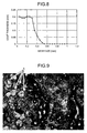
- FIG. 8 is a plot of a relation between a mesh size of a sifter and a thickness of a coat
- FIG. 9 is a photograph of a surface of a coat formed with an electrode that is manufactured using a sifter of which a mesh size is 0.5 mm;
- FIG. 10 is a flowchart of manufacturing an electrode for electric discharge surface treatment with a metallic powder or a ceramic powder having an average grain diameter of several ⁇ m;
- FIG. 11 is a flowchart of manufacturing an electrode for electric discharge surface treatment with a metallic powder less likely to be oxidized and having an average grain diameter of several tens of ⁇ m;
- FIG. 12 is a flowchart of manufacturing an electrode for electric discharge surface treatment with a metallic powder likely to be oxidized and having an average grain diameter of several tens of ⁇ m;
- FIG. 13 is a photograph of a coat formed by electric discharge surface treatment
- FIG. 14 is a flowchart of a process of manufacturing another electrode for electric discharge surface treatment according to embodiments of the present invention.
- FIG. 15 is a cross-section of a molder for molding a powder
- FIG. 16 is a conceptual view of electric discharge surface treatment performed by an apparatus for electric discharge surface treatment
- FIG. 17A is a plot of a voltage waveform (waveform of an interpole voltage) between an electrode and a work at a time of electric discharge;
- FIG. 17B is a plot of a current waveform of a current flowing through the apparatus at the time of electric discharge.
- FIG. 18 is a graph of a change in a weight of an electrode according to a time for soaking the electrode in a dielectric fluid.
- an electrode for electric discharge surface treatment with which formation of a dense thick coat by stable electric discharge without deteriorating surface roughness of the coat, and a method for manufacturing such an electrode are described.
- FIG. 1 is a schematic of the electric discharge surface treatment by the apparatus for electric discharge surface treatment.
- An apparatus for electric discharge surface treatment 1 includes a work piece (hereinafter, “work”) 11 on which a coat 14 is desired to be formed, an electrode for electric discharge surface treatment 12 for forming the coat 14 on the surface of the work 11 , a power supply for electric discharge surface treatment 13 electrically connected to the work 11 and the electrode for electric discharge surface treatment 12 for supplying a voltage to both of the work 11 and the electrode 12 to cause arc discharge therebetween.
- work work piece
- electrode for electric discharge surface treatment 12 for forming the coat 14 on the surface of the work 11
- a power supply for electric discharge surface treatment 13 electrically connected to the work 11 and the electrode for electric discharge surface treatment 12 for supplying a voltage to both of the work 11 and the electrode 12 to cause arc discharge therebetween.
- a work tank 16 is further provided so that the work 11 and a portion of the electrode for electric discharge surface treatment 12 opposed to the work 11 make contact with an oil-based dielectric fluid 15 , such as kerosene.
- an oil-based dielectric fluid 15 such as kerosene.
- the work 11 and the electrode for electric discharge surface treatment 12 are placed in a process atmosphere.
- FIG. 1 and the following description a case in which the electric discharge surface treatment is performed in a dielectric fluid is exemplarily depicted.
- the electrode for electric discharge surface treatment may be simply referred to as an electrode.
- a distance between a surface of the electrode for electric discharge surface treatment 12 and a surface of the work 11 that are opposite to each other is referred to as an interpole distance.
- the electric discharge surface treatment is performed by, for example, taking the work 11 on which the coat 14 is desired to be formed as a positive pole and the electrode for electric discharge surface treatment 12 as a negative pole using an electrode that is formed of a metal powder or a ceramic powder having an average grain diameter of 10 nanometers (nm) to several tens of ⁇ m to be a supply source of the coat 14 . While the interpole distance is controlled by a control mechanism, which is not shown, so that these poles do not make contact with each other in the dielectric fluid 15 , an electric discharge is caused to take place therebetween.
- electrode particle 21 of the electrode 12 melted by a blast or an electrostatic force by the electric discharge is separated from the electrode 12 , and is moved toward the surface of the work 11 . Then, when reaching the surface of the work 11 , the electrode particles 21 are re-coagulated into the coat 14 . A part of the separated electrode particles 21 reacts with the dielectric fluid 15 or a component 22 in an atmosphere to form a substance 23 , which also contributes to formation of the coat 14 . In this manner, the coat 14 is formed on the surface of the work 11 .
- the electrode 12 is not peeled off by the blast or the electrostatic force by the electric discharge, thereby making it impossible to supply the electrode material to the work 11 . That is, whether a thick coat can be formed by the electric discharge surface treatment depends on how the material is supplied from the electrode 12 and how the material supplied is melted on the surface of the work 11 and is bonded with the material of the material of the work 11 . How the electrode material is supplied depends on how hard the electrode 12 is, that is, hardness.
- FIG. 2 is a flowchart of a process of manufacturing the electrode for electric discharge surface treatment.
- a metallic powder or a ceramic powder that include a material that forms the coat 14 desired to be formed on the work 11 is crushed (step S 1 ). If the coat 14 is formed with several kinds of materials, powders of the materials are mixed at a desired ratio and crushed. For example, a metallic powder, a metallic alloy powder, or a ceramic spherical powder having an average grain diameter of several tens of ⁇ m that is available on the market is crushed by a mill apparatus, such as a ball mill, into grains having an average grain diameter of 3 ⁇ m or less.
- Crushing may be performed in a liquid.
- the liquid is evaporated to dry the powder (step S 2 ).
- the powder that is dried includes large solids formed due to coagulation of grains, to fragment the grains in such large solids, and to sufficiently mix the powder with wax at the next step, the powder is sifted (step S 3 ).
- the powder including coagulated solids is put on a net of which a mesh size is smaller than the interpole distance.
- a voltage applied between the electrode for electric discharge surface treatment 12 and the work 11 for causing an electric discharge is normally within a range of 80 volts (V) to 300 V.
- V volts
- the distance between the electrode 12 and the work 11 during the electric discharge surface treatment is of the order of 0.3 mm.
- an arc discharge occurring across both poles causes the coagulated solids forming the electrode 12 to be separated from the electrode without changing a size of the coagulated solids.
- an electric discharge causes the solids to be separated from the electrode 12 without changing the size of the solids.
- Such solids are deposited on the work 11 or are drifted in an interpole space between the electrode 12 and the work 11 filled with the dielectric fluid 15 .
- the electric discharge is concentrated on that place, and no electric discharge occurs at other places.
- the coat 14 cannot be uniformly deposited on the surface of the work 11 .
- the large solids cannot be completely melted by heat of the electric discharge.
- the coat 14 becomes so brittle that the coat 14 is easily scraped off by hand. Furthermore, as in the latter case, if large solids are drifted in the interpole space, a short circuit occurs between the electrode 12 and the work 11 , thereby making it impossible to cause an electric discharge. Therefore, to form the coat 14 uniformly, and to achieve stable electric discharge, solids, which is formed due to the coagulation of the grain, having a size larger than the interpole distance should not be present in the powder that forms the electrode 12 . Such coagulation of grains likely to occur in a metallic powder and conductive ceramic, and is less likely to occur in a non-conductive powder. The coagulation of grains becomes more likely to occur as the average grain diameter of the powder is made smaller.
- a process of sifting the powder coagulated at step S 3 is required.
- a mesh size at the sifting should be smaller than the interpole distance.
- the powder is mixed with wax, such as paraffin, of approximately 1% to 10% in a weight percentage as required (step S 4 ). If the powder is mixed with wax, formability improves, but the powder is again surrounded by a liquid, causing coagulation by the action of an intermolecular force or the electrostatic force and forming large solids. To fragmenting such solids formed with grains re-coagulated, the powder is sifted (step S 5 ). A method of sifting at this step is carried out in a same manner as a method at step S 3 described above.
- wax such as paraffin
- FIG. 3 is a cross-section of a molder for molding the powder.
- a lower punch 104 is inserted from a lower portion of a hole formed on a mold (die) 105 , and a space formed between the lower punch 104 and the mold (die) 105 is filled with the powder (when the powder is formed of a plurality of constituents, powder mixture) 101 .
- An upper punch 103 is then inserted from an upper portion of a hole formed on the mold (die) 105 .
- the powder 101 is compression molded with a pressure applied by a pressurizer or the like from both sides of the molder filled with the powder 101 described above by the upper punch 103 and the lower punch 104 .
- the powder 101 that is compression molded is referred to as a green compact.
- the electrode 12 becomes hard, and when a low pressure is applied, the electrode 12 becomes soft.
- the electrode 12 becomes hard, and when the grain diameter of the powder 101 is large, the electrode 12 becomes soft.
- the green compact is then removed from the molder and heated in a vacuum furnace or a furnace filled with a nitrogen atmosphere, thereby obtaining a conductive electrode (step S 7 ).
- a conductive electrode When a high heating temperature is applied, the electrode 12 becomes hard, and when a low heating temperature is applied, the electrode 12 becomes soft.
- heating the green compact it is also possible to decrease electric resistance of the electrode 12 . Therefore, even if the powder is compression molded without mixing with wax at step S 4 , heating is meaningful.
- bonding among powder particles in the green compact proceeds, thereby producing an electrode for electric discharge surface treatment 12 that has conductivity.
- the electrode for electric discharge surface treatment 12 can be molded even when the crushing process at step S 1 described above is omitted, that is, even when the powder having an average grain diameter of several tens of ⁇ m is used as it is or when the sifting process at step S 3 is omitted, and large solids as large as 0.3 mm or more are present.
- non-uniformity in hardness occurs in the electrode 12 such that hardness of a surface of the electrode is high and hardness of a center portion is low, which is not preferable.
- the center portion is consumed through the electric discharge, but portions near the surface are not consumed. Thus, deposition to the surface of the work 11 is not proceeded, which is not preferable, either.
- the electrode material at a portion of a perimeter of the electrode 12 is too hard to be supplied, thereby causing the surface of the work 11 to be removed.
- the center portion of the electrode 12 is brittle, it is consumed quickly after the process is started. As a result, the surface of the electrode 12 becomes such that its perimeter protrudes and its center portion is recessed. Since an electric discharge occurs only at the perimeter having a small interpole distance, removal of the surface of the work 11 proceeds, thereby making deposition impossible.
- powders of Co, Ni (nickel), which are less likely to be oxidized, an alloy or oxide thereof, or ceramics having an average grain diameter thereof 3 ⁇ m or less are usually available on the market. Therefore, when any of these powders is used, the crushing process at step S 1 and the drying process at step S 2 described above may be omitted.
- a stellite powder (a Co alloy having an average grain diameter of 50 ⁇ m), which is less likely to be oxidized under temperatures of 800 degrees Celsius (° C.) or lower was crushed by a vibrating mill to bring an average grain diameter to be 1.5 ⁇ m, and was then dried.
- a stellite used herein has a composition including 25 weight % Cr (chromium), 10 weight % Ni (nickel), 7 weight % W (tungsten), 0.5 weight % C (carbon), and Co for the rest.
- a stellite having a composition including 28 weight % Mo (molybdenum), 17 weight % Cr, 3 weight % Si (silicon), and Co for the rest instead of the stellite having the above structure, a stellite having a composition including 28 weight % Mo (molybdenum), 17 weight % Cr, 3 weight % Si (silicon), and Co for the rest may be used.
- a stellite having a composition including 28 weight % Mo (molybdenum), 17 weight % Cr, 3 weight % Si (silicon), and Co for the rest or a stellite having a composition including 28 weight % Cr, 5 weight % Ni, 19 weight % W, and Co for the rest may be used.
- Electrodes were manufactured using a non-sifted powder, and a sifted powder respectively.
- the dimensions of the mold used at the time of pressing were 18.2 mm in diameter and 30.5 mm in length.
- the stellite powder was compression molded at a predetermined pressure of the press, and was then heated.
- step S 3 the sifting process after drying (step S 3 ) and the sifting process after mixing paraffin (step S 5 ) were omitted to manufacture an electrode, a section photograph (scaling: 35 times) of which is shown in FIG. 4 .
- a sifter having a mesh size of 0.15 mm was used for fine crushing and, after mixing with paraffin, a sifter having a mesh size of 0.3 mm was used to manufacture an electrode.
- a section photograph of the electrode thus manufactured is shown in FIG. 5 .
- the electrode shown in FIG. 4 is examined.
- a portion appearing white is a large solid, and it can be seen that many of such portions are present in a mixed manner.
- the white portion is scratched by a pin, the portion appearing white is separated as a solid.
- FIG. 6 is a graph depicting one example of a current waveform and a voltage waveform between the poles during the electric discharge surface treatment.
- a waveform V shown in FIG. 6 at a portion near a top of the graph represents a voltage
- a waveform I shown in FIG. 6 at a portion near a bottom of the graph represents a current.
- On a vertical axis on a right end an underline drawn under 1 represents 0 A, while an underline drawn under 3 represents 0 V.
- a horizontal axis represents time in 100 millisecond (ms) divisions, while vertical axes represent in 50 V divisions on top and in 5 A divisions on bottom.
- a waveform W 1 shown on the left side from approximately the center of the drawing represents a waveform when a current is successfully generated with the application of a voltage.
- a waveform W 2 shown on the right side from approximately the center of the drawing a current waveform changes, while a voltage waveform does not change.
- a short circuit occurs between the poles. Therefore, it can be determined that the state represented by the waveform on the right side from approximately the center of the drawing is a short-circuit state.
- the coat formed by the electric discharge surface treatment using the electrode manufactured with the sifted stellite powder is shown in FIG. 7 .
- Process conditions electric-discharge pulse conditions
- the electrode for electric discharge surface treatment manufactured does not include large solids formed due to the coagulation of the powder, specifically, those larger than a distance between the electrode and the work at the time of the electric discharge surface treatment. This can prevent situations such as large solids are deposited on the work or drifted between the poles during the electric discharge surface treatment, thereby achieving a stable electric discharge. As a result, a thick coat with a smooth surface can be obtained.
- step S 2 When a powder having an average grain diameter of 3 ⁇ m or less is directly obtained from the market for manufacturing an electrode, the drying process (step S 2 ) and the subsequent sifting process (step S 3 ) are not required. Also, a powder produced by water atomization or the like has a spherical shape, and has a high moldability at the time of compression and shaping even without paraffin to be mixed. Therefore, when such a powder is used to manufacture an electrode, the paraffin mixing process (step S 4 ) and the subsequent sifting process (step S 5 ) are not required.
- a method for forming the electrode is not limited to compression molding as long as the powder is molded into an electrode.
- Method for forming the electrode other than the method by compression molding include a method with slurry, a method by metal injection molding (MIM), a method by spraying, a method of molding nano powder on a jet stream, or the like. The fact is applicable also for following embodiments.
- a powder is dispersed in a solvent, and is then put in a porous mold, such as a plaster mold, to remove the solvent, thereby molding the powder.
- a powder mixed with a binder is injected in a heated metal mold, thereby molding the powder.
- a powder that is heated is sprayed to be molded in a partially-bound state.
- a Co powder having an average grain diameter of 1 mm was used to study a relation between the size of a mesh of a sifter and the coat thickness.
- a sifted powder was used herein, the dimensions of a mold were 18.2 mm in diameter and 30.5 mm in length, and an electrode produced by compression molding the powder at a predetermined pressure of a press and then by heating a resultant compact was used. Process conditions are similar to those in the first embodiment, and the processing time was 10 minutes.
- the relation between the mesh size of the sifter and the coat thickness is shown in FIG. 8 .
- the coat thickness shown in FIG. 8 represents an average value of the coat thickness measured at five points on the coat. It is apparent from FIG. 8 that, when the mesh size exceeded 0.3 mm, the coat thickness decreased with respect to a process time, and when the mesh size was over 0.5 mm, no coat was able to be deposited.
- FIG. 9 A photograph of the surface of the coat based on an electrode manufactured using a sifter having a mesh size of 0.5 mm is shown in FIG. 9 . From FIG. 9 , it is apparent that small protruding particles A appear to be attached on the coat because large solids of the stellite powder cause a short circuit between the poles, thereby causing a large current to flow.
- the mesh size of the sifter is set as 0.3 mm, which is the distance between the electrode and the work, or smaller, it is possible to obtain a stable electric discharge and deposition of a thick coat.
- an electrode for electric discharge surface treatment that is used in forming a metallic coat by the electric discharge surface treatment, and that is formed with a powder of metal likely to be oxidized or an alloy including metal likely to be oxidized, and a method for manufacturing such an electrode.
- FIG. 10 is a flowchart of manufacturing such electrode for electric discharge surface treatment.
- a powder of metal, a metallic alloy, or ceramics having a constituent of a coat desired to be formed on the work is purchased (step S 11 ).
- a powder is available on the market and is a spherical powder of metal or ceramics that are less likely to be oxidized and that have an average grain diameter of several ⁇ m.
- the metallic powder, the metal alloy powder, or the ceramic powder is mixed with wax, such as paraffin, of approximately 1% to 10% in weight percentage as required (step S 12 ).
- step S 13 If the powder and wax are mixed together, moldability improves. However, surrounding of the powder particles are again covered with a liquid, thereby causing coagulation by the action of an intermolecular force or the electrostatic force, and forming large solids. Thus, solids formed again due to the coagulation are sifted to be fragmented (step S 13 ).
- step S 14 the powder obtained is compression molded by a compression press. Compression molding of the powder is performed using a molder in the manner described in the first embodiment described above. In the following, a solid obtained by compression molding is referred to as a green compact.
- the green compact is removed from the molder, and is then heated in a vacuum furnace or a furnace filled with the nitrogen atmosphere, thereby obtaining a conductive electrode (step S 15 ).
- a conductive electrode At the time of heating, when a high heating temperature is applied, the electrode becomes hard, and when a low heating temperature is applied, the electrode becomes soft.
- heating the green compact it is possible to decrease the electric resistance of the electrode. Therefore, even if the powder is compression molded without mixing with wax at step S 12 , heating is meaningful. With this, bonding among powder particles in the green compact proceeds, thereby obtaining an electrode for electric discharge surface treatment that has conductive.
- An electrode for electric discharge surface treatment can be manufactured in the manner as described above using a metallic powder or a ceramic powder that are less likely to be oxidized as an electrode material.
- metallic powders and ceramic powders that are less likely to be oxidized and that are available on the market are those having an average grain diameter of several ⁇ m.
- metallic powders that are likely to be oxidized and that are available on the market are limited to those having an average grain diameter of 10 ⁇ m or more.
- a ratio of the surface area to the volume of the powder increases.
- a heat capacity of the powder decreases, and the powder becomes very sensitive to energy. Therefore, for example, when a metallic powder likely to be oxidized is surrounded by oxygen, the powder is oxidized very quickly to a portion inside the powder, thereby losing its properties as metal, such as conductivity and ductility.
- oxidation of the powder may explosively proceed. That is why the metallic powder likely to be oxidized and available on the market is limited to those having a large average grain diameter of 10 ⁇ m or more.
- the metal likely to be oxidized includes Cr (chromium), Al (aluminum), and Ti (titanium).
- Cr chromium
- Al aluminum
- Ti titanium
- a method for manufacturing the electrode for electric discharge surface treatment formed with a commercially-available metallic powder that has an average grain diameter of several tens of ⁇ m, and that is less likely to be oxidized is described with reference to a flowchart shown in FIG. 11 .
- the commercially-available metallic powder having an average grain diameter of several tens of ⁇ m and less likely to be oxidized is crushed with a mill, such as a ball mill, in volatile solvent of acetone or the like into particles having an average grain diameter of 3 ⁇ m or less (step S 21 ).
- the solvent is vaporized to dry the powder (step S 22 ). Since the powder dried has large solids formed due to the coagulation of grains, to fragment these large solids and to sufficiently mix the powder with wax at a next step, the powder is sifted (step S 23 ).
- the powder is mixed with wax, such as paraffin, of approximately 1% to 10% in weight percentage as required (step S 24 ). If the powder is mixed with wax, formability improves, but the powder is again surrounded by a liquid, thereby causing the coagulation by the action of an intermolecular force or the electrostatic force, and forming large solids. To fragment the solids formed due to the re-coagulation, the powder is sifted (step S 25 ).
- wax such as paraffin
- step S 26 the powder obtained is compression molded by a compression press. Compression molding of the powder is performed using a molder in the manner described in the first embodiment described above. In the following, a solid of the powder obtained by compression molding is referred to as a green compact.
- the green compact is then removed from the molder, and is then heated in a vacuum furnace or a furnace filled with a nitrogen atmosphere, thereby obtaining a conductive electrode (step S 27 ).
- a vacuum furnace or a furnace filled with a nitrogen atmosphere thereby obtaining a conductive electrode.
- the electrode becomes hard, and when a low heating temperature is applied, the electrode becomes soft.
- heating the green compact it is possible to decrease electric resistance of the electrode 12 . Therefore, even if the powder is compression molded without mixing with wax at step S 14 , heating is meaningful. With this, bonding among powder particles in the green compact proceeds, thereby manufacturing an electrode for electric discharge surface treatment that has conductivity.
- An electrode for electric discharge surface treatment can be manufactured in the manner as described above using a commercially-available metallic powder having an average grain diameter of several tens of ⁇ m and less likely to be oxidized.
- FIG. 12 is a flowchart of manufacturing an electrode for electric discharge surface treatment according to the present invention.
- a commercially-available metallic powder likely to be oxidized has an average grain diameter of several tens of ⁇ m.
- the commercially-available metallic powder having an average grain diameter of several tens of ⁇ m and likely to be oxidized is crushed with a mill, such as a ball mill, in volatile alcohol or solvent (hereinafter, “solvent medium”) into grains having an average grain diameter of 3 ⁇ m or less (step S 31 ).
- solvent medium volatile alcohol or solvent
- the metallic powder and the solvent medium are put in a container for separation into solid and liquid.
- the electrode powder that is, the metallic powder
- the electrode powder is caused to settle in the solvent medium for removal of a supernatant of the solvent medium to obtain only the metallic powder (step S 32 ).
- the metallic powder at this time is not oxidized because the solvent medium is sufficiently contained.
- the metallic powder obtained is compression molded by a compression press without being dried (step S 33 ).
- a solid obtained by compression molding the metallic powder is referred to as a green compact.
- Compression molding of the powder is performed using a molder in the manner described in the first embodiment described above.
- the metallic powder is left being pressed by the press until a shape of an electrode is obtained, while volatilizing the solvent medium.
- a liquid having a low boiling point, such as acetone is used as the solvent medium, the solvent medium volatilizes within no more than several minutes.
- the solvent medium since what is required is that the solvent medium is dried to the extent that the green compact can keep its shape, the solvent medium does not have to be completely volatilized. Therefore, if the green compact has been dried to an extent sufficient to keep its shape, the green compact can be extracted from the molder before the solvent medium is completely dried.
- the electrode (compact) when the electrode (compact) is dried, a little space is left in a portion occupied by the solvent medium, that is, a portion between metal particles in the electrode.
- the volume of the space and oxygen that is present therein are so small that oxidation of the metallic powder does not go beyond oxidation of its surface.
- the metallic powder is in an extremely chemically-stable condition (in a high entropy condition). Therefore, even when the metallic powder having the oxidized coat formed thereon is exposed in air, a portion inside is not oxidized. Therefore, by performing steps S 31 to S 33 described above, oxidation of the metallic powder can be prevented from going beyond the oxidation on the surface.
- step S 34 heating is performed in a vacuum furnace or a furnace filled with a nitrogen atmosphere, thereby producing a conductive electrode. Even when the green compact is not completely dried during pressing, it is possible to make the solvent completely volatile during the heating process.
- An electrode for electric discharge surface treatment can be manufactured in the manner as described above using a commercially-available metallic powder that has an average grain diameter of several ⁇ m and that is likely to be oxidized.
- the mold is appropriately heated (approximately at a boiling point of a solvent medium) during pressing, it is possible to reduce time required for volatilizing the solvent medium.
- the solvent medium For example, when acetone is used as the solvent medium, it is preferable that the mold be heated at the order of 60° C. If the mold is heated at such high temperatures as 300° C. to 1000° C., the metallic powder is melted, or bonding of the metallic powder proceeds too much. Such problems do not occur with the temperature of the order of degrees above.
- each metallic powder particle forming the green compact is bonded with its many surrounding metallic powder particles to have an increased ratio of the volume to the surface area (this is virtually the same as having an increased grain diameter), and therefore, becomes insensitive to heat generated when the metallic powder is oxidized.
- the portion inside of the powder is not oxidized.
- a metallic powder having a low moldability such a metallic powder including acetone or ethanol should be mixed with wax before compression molding. Moldability can be improved if the powder is mixed with wax, such as paraffin, of approximately 1% to 10% in weight percentage to improve the transmission of pressure from the press to a portion inside of the powder at the time of a pressing process.
- wax such as paraffin
- acetone may dissolve the wax. Therefore, it is preferable to use alcohol, such as ethanol, at the time of crushing.
- the powder obtained is compression molded by a compression press in a manner similar to that above, and is then heated by a vacuum furnace or a furnace filled with a nitrogen atmosphere, thereby manufacturing a conductive electrode.
- the wax in the electrode is removed at the time of heating.
- the solvent media shown in Table 1 are examples of a solvent medium usable for the present invention. Therefore, in this invention, any solvent medium can be used as long as it has a boiling point of around 100° C., and as long as the solvent medium does not corrode a container or a press used in crushing. However, in consideration of environment, alcohols, such as ethanol, are preferable.
- the material of a ball and a container of the vibration-type ball mill was ZrO 2 , and a size of the ball was 1 ⁇ 2 inch.
- 1 kilogram (kg) of a Cr powder was put in a 3.6-liter container, and the container was filled with ethanol. The container was then vibrated to crush the Cr powder. As a result, the average grain diameter of the Cr powder was able to be reduced to 2.0 ⁇ m.
- the Cr powder crushed was extracted together with ethanol to let the Cr powder precipitate in ethanol.
- the Cr powder was allowed to precipitate for approximately 1 hour, thereby making it possible to separate the Cr powder and ethanol. Thereafter, a supernatant of ethanol was removed, thereby obtaining a Cr powder containing a large amount of ethanol.
- this compact was heated in a vacuum furnace at a predetermined heating temperature for approximately 4 hours to manufacture a conductive electrode. Ethanol was completely evaporated during heating and was removed from the electrode.
- a depositing process (electric discharge surface treatment) was performed using the electrode for electric discharge surface treatment manufactured with the Cr powder as the electrode material.
- a coat having a thickness of approximately 1 mm was able to be formed.
- a photograph of the coat formed by the electric discharge surface treatment is depicted in FIG. 13 . In the photograph shown in FIG. 13 , a thick coat of approximately 1 mm formed is shown. Concentration of the electric discharge or occurrence of a short circuit was not observed on a surface of the coat, and therefore, it can be assumed that a stable electric discharge had proceeded.
- an electrode for electric discharge surface treatment can be manufactured with oxidation of the metallic powder proceeding only on a surface and without oxidation proceeding at a portion inside of the metallic powder.
- metal likely to be oxidized can be selected as an electrode material for an electrode for electric discharge surface treatment, and a thick coat of metal likely to be oxidized, such as Ti, Al, or Cr, can be formed in a non-oxidized state by an electric discharge surface treatment.
- a thick coat having a smooth surface by excluding, when a metallic powder or a metallic compound powder is used to manufacture an electrode by compression molding, large solids formed due to the coagulation of powder particles, specifically, large solids of which a diameter is equal to or shorter than the distance between the electrode and the work, at the time of the electric discharge surface treatment.
- a Co alloy powder for example, a stellite powder
- a metallic compound powder can be used as a metallic compound powder.
- FIG. 14 is a flowchart of manufacturing the electrode for electric discharge surface treatment.
- a commercially-available metallic powder likely to be oxidized has an average grain diameter of approximately 10 ⁇ m.
- a commercially-available metallic powder likely to be oxidized and having an average grain diameter of approximately 10 ⁇ m is crushed in acetone, which is highly volatile, with a mill, such as a ball mill apparatus, into particles having an average grain diameter of 3 ⁇ m or less (step S 41 ).
- the metallic crushed powder is dried in a nitrogen atmosphere or an inert gas atmosphere.
- step S 42 only a surface of the powder is oxidized while slightly taking air in.
- the metallic powder likely to be oxidized is exposed to oxygen, the metallic powder is oxidized, as a matter of course.
- oxidation of the metallic powder proceeds only on the surface of the powder.
- the metallic powder is in an extremely chemically-stable condition (in a high entropy condition). Therefore, even when the metallic powder having the oxidized coat formed thereon is exposed in air, the portion inside is not oxidized.
- Such a process of forming an oxidized coat on a metallic powder is referred to as a gradual oxidizing process.
- the metallic powder after drying may form large solids due to the coagulation of particles.
- the powder is mixed with wax, such as paraffin, of approximately 1% to 10% in weight percentage before pressing, thereby making it possible to improve formability of the metallic powder.
- the metallic powder after drying is sifted so that wax, such as paraffin, and the metallic powder are mixed well with each other, thereby clearing the coagulation of the metallic powder (step S 43 ).
- the powder is mixed with wax, such as paraffin, of approximately 1% to 10% in weight percentage as required before pressing (step S 44 ).
- wax such as paraffin
- the powder is again surrounded by a liquid, thereby causing the coagulation by the action of the intermolecular force or the electrostatic force, and forming large solids.
- the powder is sifted (step S 45 ).
- step S 46 the powder obtained is molded by a compression press. Compression molding the powder is performed using a molder in the manner described in the first embodiment described above. In the following, a solid of the powder obtained by compression molding is referred to as a green compact.
- the green compact is removed from the molder, and is then heated in a vacuum furnace or a furnace filled with a nitrogen atmosphere, thereby obtaining a conductive electrode (step S 47 ).
- An electrode for electric discharge surface treatment can be manufactured in the manner as described above with, as an electrode material, a commercially-available metallic powder that has an average grain diameter of approximately 10 ⁇ m, and that is likely to be oxidized.
- a Cr powder commercially available has an average grain diameter of the order of 10 ⁇ m.
- Such a powder was first crushed by a vibration-type ball mill. Crushing conditions were similar to those in the third embodiment described above, and crushing was performed under conditions similar to those shown in Tables 1 and 2. That is, the material of a ball and a container in the vibration-type ball mill was ZrO 2 , and the size of the ball was 1 ⁇ 2 inch. 1 kg of a Cr powder was put in a 3.6-liter container, and the container was filled with acetone as a solvent medium. The container was then vibrated to crush the Cr powder. As a result, the average grain diameter of the Cr powder was able to be reduced to 2.0 ⁇ m.
- the Cr powder after crushing was put in a container and placed in a drying apparatus, and then was dried by being cooled with chiller water at a temperature of approximately 10° C.
- the Cr powder dried weighed approximately 1 kg.
- the Cr powder dried was uniformly spread at a bottom of an approximately 100-liter container.
- the container was first filled with nitrogen, and then air is injected at 0.2 liter (L) per minute in the container so that a volume ratio of nitrogen and air was 9:1.
- the temperature inside the container was kept at 60° C. and left for approximately 5 hours. In this manner, the surface of the Cr powder crushed was slightly oxidized. In other words, the surface of the Cr powder crushed was gradually oxidized.
- electric resistance of the electrode for electric discharge surface treatment manufactured is of the order of 10 kilo-ohms (k ⁇ ), and therefore, an electric discharge cannot be achieved even by performing an electric discharge surface treatment using the electrode for electric discharge surface treatment.
- the pressure of the press is increased to some extent at the time of compressing and molding, the oxidized coat of the Cr powder is broken, thereby reducing the electric resistance of the electrode manufactured to approximately 10.
- the metallic powder With an oxidized coat being formed on the surface of the metallic powder, the metallic powder is chemically stabilized, and is therefore, easy to handle as normal ceramics.
- an electrode for electric discharge surface treatment can be molded by a manufacturing method similar to the conventional method.
- an oxide is generally non-conductive. Therefore, a conductive electrode for electric discharge surface treatment cannot be manufactured unless the oxidized coat of the metallic powder is broken by heating or pressing. With an electrode for electric discharge surface treatment manufactured without the oxidized coat of the metallic powder being broken, that is, a non-conductive electrode for electric discharge surface treatment, an electric discharge cannot be generated, as a matter of course.
- the oxidized coat of the metallic powder should be broken by applying a predetermined pressure at the time of compression molding, thereby causing a metallic bond between metallic powders. As a result, the electrode manufactured has conductivity, and with the electrode, it is possible to generate an electric discharge, thereby making the electric discharge surface treatment possible.
- a sifter having a mesh size of 0.15 mm was used to finely crush the Cr powder. Then, the Cr powder finely-crushed was mixed with paraffin of 8% in weight percentage, and was then finely crushed again by a sifter having a mesh size of 0.05 mm.
- a depositing process (electric discharge surface treatment) was performed using the electrode for electric discharge surface treatment manufacture with this Cr powder as the electrode material.
- the electric discharge surface treatment performing for 3 minutes, a coat having a thickness of approximately 1 mm was able to be formed. Concentration of the electric discharge or occurrence of a short circuit was not observed on a surface of the coat, and therefore, it can be assumed that a stable electric discharge had proceeded.
- an electrode for electric discharge surface treatment can be manufactured without oxidation proceeding to the portion inside of the metallic powder and with oxidation of the metallic powder proceeding only to the surface.
- metal likely to be oxidized can be selected as an electrode material for an electrode for electric discharge surface treatment, and a thick coat of metal likely to be oxidized, such as Ti, Al, or Cr, can be formed as being in a non-oxidized state by the electric discharge surface treatment.
- an oxidized coat is formed on the surface of the metallic powder likely to be oxidized, thereby obtaining a chemically-stable metallic powder.
- the powder becomes easy to handle as ceramics.
- an electrode for electric discharge surface treatment can be manufactured by a manufacturing method similar to the conventional method.
- a heating wire is wound around a side surface of a container of a mill container, such as a ball mill apparatus.
- An input to the heating wire is adjusted such that an inner wall of the container becomes at a temperature of 60° C. to 80° C.
- Alcohol (propanol or butanol) having a boiling point of 100° C. or higher is then put in the container.
- wax of 5 weight % to 10 weight % in weight percentage with respect to a powder to be crushed is put in the container.
- Wax having a melting point of approximately 50° C. is used.
- a ball made of zirconia for crushing and the powder to be crushed are put in the container.
- the amount of each input is similar to that in the third embodiment.
- the kinematic viscosity of the melted wax is approximately three times as high as the kinematic viscosity of alcohol, thereby increasing an influence the solvent medium on the ball in resistance. To complete crushing within a time as short as the time required fro crushing when alcohol is used, it is required to increase the number of vibrations to some extent.
- the powder is covered with wax even after alcohol is dried, and therefore does not make contact with air, thereby obtaining a powder that is not oxidized. Also, compared with the manufacturing method according to the fourth embodiment, the sifting process can be omitted.
- an electrode material such as Ti
- the electrode for electric discharge surface treatment includes a large amount of material easy to form carbide.
- a material on a surface of a work piece (work) is changed, thereby changing characteristics, such as a thermal conductivity and a melting point, accordingly.
- characteristics such as a thermal conductivity and a melting point
- Examples of an electrode for electric discharge surface treatment with which formation of a thick coat is possible as described above are listed below.
- the temperatures in the heating process shown below were obtained through experiments performed by the inventors.
- Electrode for electric discharge surface treatment manufactured by compression molding a Co powder and by further performing a heating process
- the temperature in the heating process after compression molding is preferably 400° C. to 600° C.
- the temperature in the heating process after compression molding is preferably 100° C. to 300° C.
- the temperature in the heating process after compression molding may be 200° C. or lower, or in some cases, the heating process is not required.
- Electrode for electric discharge surface treatment manufactured by compression molding a powder of an alloy hard to form a carbide, such as Co, and by further performing a heating process
- An electrode for electric discharge surface treatment manufactured by compression molding a Co-based alloy powder (a grain diameter of 1 ⁇ m to 3 ⁇ m) that includes 25 weight % Cr (chromium), 10 weight % Ni (nickel), 7 weight % W (tungsten), and the like, and by further performing the heating process can also form a dense thick coat.
- the temperature in the heating process after compression molding is preferably higher than that for the Co powder because of a material difference, of the order of 700° C. to 900° C.
- a thick coat can be formed by the electric discharge surface treatment, as long as certain conditions are satisfied, such that a predetermined amount (for example, 40 weight % or more) of a material hard to be carbonized should be included.
- an electrode for electric discharge surface treatment formed of a 100% Fe (iron) material, or with an electrode for electric discharge surface treatment formed of a steel material formation of a thick coat by the electric discharge surface treatment is possible.
- an electrode for electric discharge surface treatment formed of Ni (nickel) or the like allows formation of a thick coat in a electric discharge surface treatment.
- a Co-based alloy powder (a grain diameter of 1 ⁇ m to 3 ⁇ m) that includes 25 weight % Cr (chromium), 10 weight % Ni (nickel), 7 weight % W (tungsten), and the like was compression molded, and then the heating process was further performed at a temperature of 800° C. to manufacture an electrode for electric discharge surface treatment. Then, the electric discharge surface treatment was performed using this electrode for electric discharge surface treatment to form a coat on a work of an Ni alloy. Specific description is provided below.
- FIG. 15 is a cross-section of a molder for molding the powder.
- a lower punch 203 was inserted from a lower portion of a hole formed on a mold (die) 204 , and a space formed between the lower punch 203 and the mold (die) 204 was filled with a Co-based alloy powder 201 including 25 weight % Cr (chromium), 10 weight % Ni (nickel), 7 weight % W (tungsten), and the like.
- the alloy powder 201 was compression molded by a pressure applied by a pressurizer or the like from both sides of the molder filled with the powder 201 described above by the upper punch 202 and the lower punch 203 .
- the alloy powder 201 compression molded is referred to as a green compact.
- the green compact is then removed from the molder and heated in a vacuum furnace at a temperature of 800° C., thereby obtaining a conductive compact electrode, that is, the electrode for electric discharge surface treatment.
- the alloy powder 201 is mixed with wax, such as paraffin, thereby improving moldability of the alloy powder 201 .
- wax is an insulating material, if a large amount of wax remains in the electrode, the electric resistance of the electrode increases, thereby degrading the electric discharge property.
- Wax can be removed by putting the green compact in the vacuum furnace to be heated. In addition, by heating the green compact, it is possible to decrease the electric resistance of the green compact, and to increase strength of the green compact. Therefore, even when wax is not mixed, heating after compression molding is meaningful.
- FIG. 16 a state is shown in which a pulse-like electric discharge occurs.
- the apparatus for electric discharge surface treatment shown in FIG. 16 includes an electrode for electric discharge surface treatment 301 (hereinafter, simply “electrode 301 ”), a dielectric fluid 303 covering an electrode 301 and a work 302 made of the Ni alloy, and a power supply for electric discharge surface treatment 304 that causes a pulse-like electric discharge by applying a voltage between the electrode 301 and the work 302 .
- electrode 301 an electrode for electric discharge surface treatment 301
- dielectric fluid 303 covering an electrode 301 and a work 302 made of the Ni alloy
- a power supply for electric discharge surface treatment 304 that causes a pulse-like electric discharge by applying a voltage between the electrode 301 and the work 302 .
- a servo mechanism for controlling an interpole distance that is, a distance between the electrode 301 and the work 302 , a depot storing the dielectric fluid 303 , and the like are omitted because they are not directly related to the present invention.
- the electrode 301 and the work 302 are placed in the dielectric fluid 303 to be opposed to each other. Then, in the dielectric fluid 303 , a pulse-like electric discharge is caused between the electrode 301 and the work 302 by using the power supply for electric discharge surface treatment 304 . Specifically, a voltage is applied between the electrode 301 and the work 302 to cause an electric discharge. As shown in FIG. 16 , an arc column of electric discharge 305 occurs between the electrode 301 and the work 302 .
- the electrode 301 has a negative polarity
- the work 302 has a positive polarity
- FIGS. 17A and 17B are diagrams of examples of pulse conditions of electric discharge in the electric discharge surface treatment, in which FIG. 17A depicts a voltage waveform (waveform of an interpole voltage) between the electrode 301 and the work 302 at the time of electric discharge, while FIG. 17B depicts a current waveform of a current flowing through the apparatus for electric discharge surface treatment at the time of electric discharge.
- a voltage value and a current value are each positive in a direction of an arrow shown in each of FIGS. 17A and 17B , that is, in an upper direction of a vertical axis.
- the current value is positive when the electrode 301 side has a negative polarity, while the work 302 is as a positive-polarity electrode.
- a no-load voltage ui is applied between both poles at a time t 0 .
- a current begins to flow at a time t 1 after an electric-discharge delay time td has elapsed, thereby starting the electric discharge.
- the voltage at this time is an electric-discharge voltage ue, and the current at this time is represented by a peak current value ie. Then, when the supply of the voltage between both poles is stopped at a time t 2 , the current stops flowing.
- a duration between t 2 to t 1 is referred to as an electric-discharge pulse width te.
- a voltage waveform in a duration between t 0 to t 2 is repeatedly applied between both poles at intervals of a pause time to. That is, as shown in FIG. 17A , a pulse-like voltage is applied between the electrode 301 and the work 302 .
- a dense, thick coat was able to be formed by performing an electric discharge surface treatment with the structure and conditions described above.
- a problem occurred in which, the coat thickness of the coat formed differed every time the process was performed even with the process performed under the same conditions and for the same time duration.
- the amount of deposition (coat thickness) of the coat when a brand-new electrode 301 was used was approximately 150 ⁇ m
- the coat thickness of the formed coating when an electrode 301 previously used several days ago was used for performing an electric discharge surface treatment was approximately 100 ⁇ m.
- the coat thickness of the formed coating varies even if the process is performed under the same conditions, it is inconvenient in view of automating the process when, for example, coatings are successively formed on the same component. That is, since the coat thickness of the coat cannot be controlled, a coat is formed to be thick, and then a process of removing an excess coating is required. This is disadvantageous in terms of process time and cost.
- the cause of variations in coat thickness of the coat is due to an inflow of oil, which is a dielectric fluid used in the electric discharge surface treatment, in the space between the poles. Since the electrode for electric discharge surface treatment is compression molded from a powdered material, its inside is in a state where many spaces are present. Then, several tens of % of a volume of the electrode is such spaces, and these spaces play an important role in forming a coat by the electric discharge surface treatment.
- oil which is a dielectric fluid used in the electric discharge surface treatment
- the electrode material is not normally supplied by an electric-discharge pulse and a phenomenon occurs such that, upon impact of the electric discharge, the electrode collapses over a wide range.
- the electrode material is too closely and firmly formed, thereby causing a phenomenon of a short supply of the electrode material by an electric-discharge pulse and making it impossible to form a thick coat.
- the spaces in the electrode for electric discharge surface treatment are important in forming a coat.
- the spaces in the electrode for electric discharge surface treatment also produce variations in coat thickness of the coat. That is, when the electrode for electric discharge surface treatment is brand-new, the spaces in the electrode are in a hollow state.
- oil which is the dielectric fluid, flows into the spaces inside the electrode, and the spaces are filled with oil.
- the electrode can be prevented from being excessively consumed due to the electric discharge at the electric discharge surface treatment, thereby making it easy to form a dense coating.
- the above (three) effects mentioned above vary with time, which causes the variations in the coat thickness of the coat. Therefore, the more the electrode is used, that is, the more the electrode is soaked in the dielectric fluid, the thinner the coat becomes even though the electric discharge surface treatment is performed under the same conditions and for the same time duration. Hence, the thickness of the coat decreases.
- the present embodiment has a feature in which the electrode for electric discharge surface treatment is soaked in a dielectric fluid to fill the spaces in the electrode with the dielectric fluid in advance, thereby suppressing variations in coat thickness of the coat at the time of the electric discharge surface treatment.
- a powdered material that is, any one of a metallic powder, a metal compound powder, and a ceramic powder
- a powdered material that is, any one of a metallic powder, a metal compound powder, and a ceramic powder
- oil or a dielectric fluid used in the electric discharge surface treatment is caused to flow into the space inside the green compact.
- the processes up to the process of forming the green compact are similar to those for manufacturing the electrode for electric discharge surface treatment described above.
- the electrode for electric discharge surface treatment is manufactured in the manner described above, and the electrode is filled with oil or a dielectric fluid used in the electric discharge surface treatment in the space inside the electrode for electric discharge surface treatment in advance before being used for the electric discharge surface treatment.
- the green compact electrode that is, the electrode for electric discharge surface treatment
- the electric discharge surface treatment is performed with the electrode of which the space in the electrode for electric discharge surface treatment is filled with oil or the dielectric solution. Therefore, variations that occur in process between a brand-new electrode and an electrode for which a predetermined time has elapsed since manufactured can also be minimized.
- FIG. 18 depicts a state in which a weight of the electrode increases according to a time for soaking the electrode in a dielectric fluid. Amount of increase in weight of the electrode is equivalent to an amount of the dielectric fluid absorbed in the electrode. From FIG. 18 , it can be assumed that the dielectric fluid flows into the space in the electrode within 2 hors to 3 hours.
- a Co-based alloy powder (a grain diameter of 1 ⁇ m to 3 ⁇ m) that includes Cr (chromium), Ni (nickel), W (tungsten), and the like was compression molded, and then the heating process was further performed at a temperature of 800° C. Thereafter, the electrode having been soaked in the dielectric fluid for 30 hours was used for the electric discharge surface treatment for a work of an Ni alloy.
- electric-discharge pulse conditions were such that the electrode for use had an electrode area (that is, an area to be processed) of 18 mm, and the peak current value is 10 A, the pulse width is 8 ⁇ s, and the pause time is 16 ⁇ s, and the process was performed for 10 minutes.
- an amount of deposition (coat thickness) with the use of a brand-new electrode was approximately 100 ⁇ m, and the amount when a process was performed 7 days later under the same conditions was also approximately 100 ⁇ m.
- variations in thickness of the coat were able to be nearly solved.
- the compact electrode manufactured that is, the electrode for electric discharge surface treatment
- the electric discharge surface treatment is performed with the green compact electrode of which the spaces inside are filled with the dielectric fluid. Therefore, the variations that occur in the process between a brand-new electrode and even an electrode produced after a predetermined time has elapsed can also be minimized.
- the electrode for electric discharge surface treatment (compact electrode)
- the electrode is stored in air
- the dielectric fluid in the spaces inside the electrode evaporates. Therefore, to eliminate the variations in coat formed by the electric discharge surface treatment, it is preferable that the electrode is stored in oil similar to the dielectric liquid. Flow of the dielectric fluid into the electrode is completed in several hours.
- constituents prone to evaporation in the dielectric fluid evaporate, while those resistant to evaporation remains in the electrode. This affects binding strength of powder particles of the electrode material, and also affects a condition of the coat to be formed at the time of performing the electric discharge surface treatment with the electrode. Therefore, it is preferable that the electrode is stored in the dielectric solution.
- the electrode is not particularly required to be soaked in oil, as long as the electrode is set within a time in which the dielectric fluid absorbed in the electrode does not evaporate, and the electrode may be left in air.
- the electrode for electric discharge surface treatment is stored in oil, thereby preventing not only variations in the hardness of the electrode with time, but also oxidation of the electrode material. If the electrode includes an electrode material likely to be oxidized, when the electrode is stored in air for a long time, oxidation of the electrode material proceeds to affect a quality of the electrode and a quality of the coat to be formed. Therefore, by storing the electrode in oil, it is possible prevent the oxidation of the electrode material, and to stabilize the quality of the electrode and the quality of the coat formed by the electric discharge surface treatment using the electrode.
- the electrode for electric discharge surface treatment When the electrode for electric discharge surface treatment is stored in this manner, it is possible to effectively prevent deterioration in a quality of the electrode due to hardening or the like by storing the electrode in a package.
- the electrode may be packaged by vacuum packaging, soon after the electrode is manufactured.
- the influence upon the formation of the coat of the dielectric absorbed in the electrode has been mentioned.
- soaking the electrode in the dielectric fluid is effective in preventing the oxidation of the electrode material.
- the powder material of the electrode changes into ceramics, thereby making it difficult to form a dense coat.
- it is also effective to store the electrode in a vacuum package or in an inert gas (a noble gas), such as helium or argon, or an inert gas, such as nitrogen.
- a noble gas such as helium or argon
- an inert gas such as nitrogen
- the electrode for electric discharge surface treatment is stored in vacuum or an inert gas, thereby preventing oxidation of the powder material of the electrode. As a result, even an electrode in which a long time has elapsed since manufactured can form a dense coat.
- an electrode for electric discharge surface treatment with which surface treatment in which a stable electric discharge is generated, and in which a thick coat can be formed without deteriorating surface roughness.
- an electrode with a metallic powder likely to be oxidized without making the metallic powder oxidized during a manufacturing process, and is possible to form a thick metallic coat by electric discharge surface treatment.
- the electrode for electric discharge surface treatment When the electrode for electric discharge surface treatment is stored in this manner, it is possible to effectively prevent deterioration in a quality of the electrode due to hardening or the like by storing the electrode in a package.
- the electrode may be packaged by vacuum packaging, soon after the electrode is manufactured.
Landscapes
- Chemical & Material Sciences (AREA)
- Engineering & Computer Science (AREA)
- Mechanical Engineering (AREA)
- Chemical Kinetics & Catalysis (AREA)
- Materials Engineering (AREA)
- Metallurgy (AREA)
- Organic Chemistry (AREA)
- Manufacturing & Machinery (AREA)
- Other Surface Treatments For Metallic Materials (AREA)
- Powder Metallurgy (AREA)
- Ceramic Capacitors (AREA)
- Fixed Capacitors And Capacitor Manufacturing Machines (AREA)
Applications Claiming Priority (7)
| Application Number | Priority Date | Filing Date | Title |
|---|---|---|---|
| JP2003-158897 | 2003-06-04 | ||
| JP2003158897 | 2003-06-04 | ||
| JP2003-160507 | 2003-06-05 | ||
| JP2003160507 | 2003-06-05 | ||
| JP2003-166012 | 2003-06-11 | ||
| JP2003166012 | 2003-06-11 | ||
| PCT/JP2004/001471 WO2004108989A1 (ja) | 2003-06-04 | 2004-02-12 | 放電表面処理用電極及びその製造方法並びにその保管方法 |
Related Parent Applications (1)
| Application Number | Title | Priority Date | Filing Date |
|---|---|---|---|
| PCT/JP2004/001471 Continuation-In-Part WO2004108989A1 (ja) | 2003-06-04 | 2004-02-12 | 放電表面処理用電極及びその製造方法並びにその保管方法 |
Publications (2)
| Publication Number | Publication Date |
|---|---|
| US20060081462A1 US20060081462A1 (en) | 2006-04-20 |
| US7915559B2 true US7915559B2 (en) | 2011-03-29 |
Family
ID=33514557
Family Applications (1)
| Application Number | Title | Priority Date | Filing Date |
|---|---|---|---|
| US11/291,878 Active 2027-10-04 US7915559B2 (en) | 2003-06-04 | 2005-12-02 | Electrode for electric discharge surface treatment, method for manufacturing electrode, and method for storing electrode |
Country Status (10)
| Country | Link |
|---|---|
| US (1) | US7915559B2 (ja) |
| EP (1) | EP1630255B1 (ja) |
| JP (1) | JP4641260B2 (ja) |
| KR (1) | KR100753274B1 (ja) |
| CN (1) | CN1798873B (ja) |
| BR (1) | BRPI0411033A (ja) |
| CA (1) | CA2525761A1 (ja) |
| RU (1) | RU2335382C2 (ja) |
| TW (1) | TWI279272B (ja) |
| WO (1) | WO2004108989A1 (ja) |
Cited By (4)
| Publication number | Priority date | Publication date | Assignee | Title |
|---|---|---|---|---|
| US20090214352A1 (en) * | 2005-03-09 | 2009-08-27 | Ihi Corporation | Surface treatment method and repair method |
| US20100124490A1 (en) * | 2002-10-09 | 2010-05-20 | Ihi Corporation | Rotating member and method for coating the same |
| US9187831B2 (en) | 2002-09-24 | 2015-11-17 | Ishikawajima-Harima Heavy Industries Co., Ltd. | Method for coating sliding surface of high-temperature member, high-temperature member and electrode for electro-discharge surface treatment |
| US9284647B2 (en) | 2002-09-24 | 2016-03-15 | Mitsubishi Denki Kabushiki Kaisha | Method for coating sliding surface of high-temperature member, high-temperature member and electrode for electro-discharge surface treatment |
Families Citing this family (12)
| Publication number | Priority date | Publication date | Assignee | Title |
|---|---|---|---|---|
| WO2004111301A1 (ja) | 2003-06-10 | 2004-12-23 | Mitsubishi Denki Kabushiki Kaisha | 放電表面処理用電極とその評価方法、および放電表面処理方法 |
| WO2007043102A1 (ja) * | 2005-09-30 | 2007-04-19 | Mitsubishi Denki Kabushiki Kaisha | 放電表面処理用電極及び放電表面処理方法並びに被膜 |
| US9249492B2 (en) * | 2005-11-07 | 2016-02-02 | Micropyretics Heaters International, Inc. | Materials having an enhanced emissivity and methods for making the same |
| CN101495677B (zh) * | 2006-04-05 | 2011-08-31 | 三菱电机株式会社 | 覆膜以及覆膜的形成方法 |
| US9347137B2 (en) | 2006-09-11 | 2016-05-24 | Ihi Corporation | Method of manufacturing electrode for electrical-discharge surface treatment, and electrode for electrical-discharge surface treatment |
| US8372313B2 (en) | 2007-11-19 | 2013-02-12 | Mitsubishi Electric Corporation | Electrical-discharge surface-treatment electrode and metal coating film formed using the same |
| JP5172465B2 (ja) * | 2008-05-20 | 2013-03-27 | 三菱電機株式会社 | 放電表面処理用電極の製造方法および放電表面処理用電極 |
| JP5354010B2 (ja) | 2009-04-14 | 2013-11-27 | 株式会社Ihi | 放電表面処理用電極及びその製造方法 |
| RU2653395C1 (ru) * | 2017-07-11 | 2018-05-08 | Федеральное государственное бюджетное образовательное учреждение высшего образования "Сибирский государственный индустриальный университет" | Способ нанесения износостойких покрытий на основе карбида титана, Cr3 C2 и алюминия на штамповые стали |
| WO2022006468A1 (en) * | 2020-07-02 | 2022-01-06 | Ultima Genomics, Inc. | Methods and systems for nucleic acid analysis |
| CN114231970A (zh) * | 2021-12-02 | 2022-03-25 | 中原工学院 | 一种宽温域自润滑复合涂层及其制备工艺 |
| CN117086419B (zh) * | 2023-06-29 | 2025-09-30 | 深圳大学 | 一种固粉复合材料电极的制备方法及装置 |
Citations (20)
| Publication number | Priority date | Publication date | Assignee | Title |
|---|---|---|---|---|
| SU1479208A1 (ru) | 1987-05-07 | 1989-05-15 | Научно-Производственное Объединение "Магнетон" | Способ изготовлени анизотропных ферритбариевых магнитов |
| US4954169A (en) | 1988-06-22 | 1990-09-04 | Bayer Aktiengesellschaft | Fine-grained, high-purity earth acid metal powders, a process for their production and their use |
| JPH05148615A (ja) | 1991-11-18 | 1993-06-15 | Res Dev Corp Of Japan | 金属材料の表面処理方法 |
| RU2023316C1 (ru) | 1991-04-22 | 1994-11-15 | Научно-Производственное Объединение "Магнетон" | Способ изготовления анизотропных ферритовых магнитов |
| KR950007174B1 (ko) | 1992-10-22 | 1995-07-03 | 쌍용양회공업주식회사 | 시계 케이스용 경질 합금의 제조방법 |
| JPH07197275A (ja) | 1993-12-31 | 1995-08-01 | Res Dev Corp Of Japan | 液中放電による金属材料の表面処理方法 |
| JPH08300227A (ja) | 1995-04-14 | 1996-11-19 | Res Dev Corp Of Japan | 放電加工用電極および放電による金属表面処理方法 |
| DE19701170A1 (de) | 1996-01-17 | 1997-07-24 | Japan Science & Tech Corp | Verfahren zur Oberflächenbehandlung mittels elektrischer Entladung |
| JPH11229159A (ja) | 1998-02-16 | 1999-08-24 | Mitsubishi Electric Corp | 放電表面処理装置およびこれを用いた放電表面処理方法 |
| WO1999058744A1 (en) | 1998-05-13 | 1999-11-18 | Mitsubishi Denki Kabushiki Kaisha | Electrode for discharge surface treatment and manufacturing method thereof and discharge surface treatment method and device |
| JP2000096105A (ja) | 1998-09-22 | 2000-04-04 | Ishifuku Metal Ind Co Ltd | 放電被覆用電極製造方法及びその方法により製造された放電被覆用電極 |
| WO2001005545A1 (fr) | 1999-07-16 | 2001-01-25 | Mitsubishi Denki Kabushiki Kaisha | Electrode pour traitement de surface par decharge et procede de production de celle-ci |
| CN1286733A (zh) | 1998-03-16 | 2001-03-07 | 三菱电机株式会社 | 放电表面处理方法和实施该方法的装置及电极 |
| WO2001023641A1 (en) | 1999-09-30 | 2001-04-05 | Mitsubishi Denki Kabushiki Kaisha | Electric discharge surface treating electrode and production method thereof and electric discharge surface treating method |
| WO2001023640A1 (fr) | 1999-09-30 | 2001-04-05 | Mitsubishi Denki Kabushiki Kaisha | Electrode de traitement de surface par decharge electrique, son procede de production et procede de traitement de surface par decharge electrique |
| US20010014405A1 (en) | 1998-11-13 | 2001-08-16 | Takashi Yuzawa | Surface treatment method using electric discharge, and an electrode for the surface treatment method |
| US20010013508A1 (en) | 1998-11-13 | 2001-08-16 | Akihiro Goto | Method of surface treatment using electric discharge and an electrode |
| US6441333B1 (en) | 1998-03-11 | 2002-08-27 | Mitsubishi Denki K.K. | Green compact electrode for discharge surface treatment and method of manufacturing green compact electrode for discharge surface treatment |
| US6793982B1 (en) | 1998-05-13 | 2004-09-21 | Mitsubishi Denki Kabushiki Kaisha | Electrode of green compact for discharge surface treatment, method of producing the same, method of discarge surface treatment, apparatus therefor, and method of recycling electrode of green compact for discharge surface treatment |
| US6935917B1 (en) | 1999-07-16 | 2005-08-30 | Mitsubishi Denki Kabushiki Kaisha | Discharge surface treating electrode and production method thereof |
-
2004
- 2004-02-12 RU RU2005141421/02A patent/RU2335382C2/ru not_active IP Right Cessation
- 2004-02-12 EP EP04710516.8A patent/EP1630255B1/en not_active Expired - Lifetime
- 2004-02-12 JP JP2005506726A patent/JP4641260B2/ja not_active Expired - Lifetime
- 2004-02-12 WO PCT/JP2004/001471 patent/WO2004108989A1/ja not_active Ceased
- 2004-02-12 BR BRPI0411033-1A patent/BRPI0411033A/pt not_active Application Discontinuation
- 2004-02-12 KR KR1020057023285A patent/KR100753274B1/ko not_active Expired - Fee Related
- 2004-02-12 CN CN2004800153641A patent/CN1798873B/zh not_active Expired - Lifetime
- 2004-02-12 CA CA002525761A patent/CA2525761A1/en not_active Abandoned
- 2004-02-19 TW TW093104055A patent/TWI279272B/zh not_active IP Right Cessation
-
2005
- 2005-12-02 US US11/291,878 patent/US7915559B2/en active Active
Patent Citations (26)
| Publication number | Priority date | Publication date | Assignee | Title |
|---|---|---|---|---|
| SU1479208A1 (ru) | 1987-05-07 | 1989-05-15 | Научно-Производственное Объединение "Магнетон" | Способ изготовлени анизотропных ферритбариевых магнитов |
| US4954169A (en) | 1988-06-22 | 1990-09-04 | Bayer Aktiengesellschaft | Fine-grained, high-purity earth acid metal powders, a process for their production and their use |
| KR970001559B1 (ko) | 1988-06-22 | 1997-02-11 | 헤르만 씨. 스타르크 베를린 지엠비에치 앤드 캄파니 케이지 | 미립 고순도 토산금속분말, 이의 제조방법, 이를 포함하는 소결전극 및 전해질 축전기 |
| RU2023316C1 (ru) | 1991-04-22 | 1994-11-15 | Научно-Производственное Объединение "Магнетон" | Способ изготовления анизотропных ферритовых магнитов |
| JPH05148615A (ja) | 1991-11-18 | 1993-06-15 | Res Dev Corp Of Japan | 金属材料の表面処理方法 |
| KR950007174B1 (ko) | 1992-10-22 | 1995-07-03 | 쌍용양회공업주식회사 | 시계 케이스용 경질 합금의 제조방법 |
| JPH07197275A (ja) | 1993-12-31 | 1995-08-01 | Res Dev Corp Of Japan | 液中放電による金属材料の表面処理方法 |
| JPH08300227A (ja) | 1995-04-14 | 1996-11-19 | Res Dev Corp Of Japan | 放電加工用電極および放電による金属表面処理方法 |
| DE19701170A1 (de) | 1996-01-17 | 1997-07-24 | Japan Science & Tech Corp | Verfahren zur Oberflächenbehandlung mittels elektrischer Entladung |
| JPH11229159A (ja) | 1998-02-16 | 1999-08-24 | Mitsubishi Electric Corp | 放電表面処理装置およびこれを用いた放電表面処理方法 |
| US6441333B1 (en) | 1998-03-11 | 2002-08-27 | Mitsubishi Denki K.K. | Green compact electrode for discharge surface treatment and method of manufacturing green compact electrode for discharge surface treatment |
| CN1286733A (zh) | 1998-03-16 | 2001-03-07 | 三菱电机株式会社 | 放电表面处理方法和实施该方法的装置及电极 |
| WO1999058744A1 (en) | 1998-05-13 | 1999-11-18 | Mitsubishi Denki Kabushiki Kaisha | Electrode for discharge surface treatment and manufacturing method thereof and discharge surface treatment method and device |
| US6793982B1 (en) | 1998-05-13 | 2004-09-21 | Mitsubishi Denki Kabushiki Kaisha | Electrode of green compact for discharge surface treatment, method of producing the same, method of discarge surface treatment, apparatus therefor, and method of recycling electrode of green compact for discharge surface treatment |
| JP3227454B2 (ja) | 1998-05-13 | 2001-11-12 | 三菱電機株式会社 | 放電表面処理用電極及びその製造方法並びに放電表面処理方法及び装置 |
| JP2000096105A (ja) | 1998-09-22 | 2000-04-04 | Ishifuku Metal Ind Co Ltd | 放電被覆用電極製造方法及びその方法により製造された放電被覆用電極 |
| US20010013508A1 (en) | 1998-11-13 | 2001-08-16 | Akihiro Goto | Method of surface treatment using electric discharge and an electrode |
| US20010014405A1 (en) | 1998-11-13 | 2001-08-16 | Takashi Yuzawa | Surface treatment method using electric discharge, and an electrode for the surface treatment method |
| CH694120A5 (de) | 1999-07-16 | 2004-07-30 | Mitsubishi Electric Corp | Verfahren zum Herstellen einer Elektrode für Funkenoberflächenbehandlung. |
| WO2001005545A1 (fr) | 1999-07-16 | 2001-01-25 | Mitsubishi Denki Kabushiki Kaisha | Electrode pour traitement de surface par decharge et procede de production de celle-ci |
| US6935917B1 (en) | 1999-07-16 | 2005-08-30 | Mitsubishi Denki Kabushiki Kaisha | Discharge surface treating electrode and production method thereof |
| WO2001024961A1 (en) | 1999-09-30 | 2001-04-12 | Mitsubishi Denki Kabushiki Kaisha | Electrode for discharge surface treating and production method thereof and discharge surface treating method |
| WO2001023640A1 (fr) | 1999-09-30 | 2001-04-05 | Mitsubishi Denki Kabushiki Kaisha | Electrode de traitement de surface par decharge electrique, son procede de production et procede de traitement de surface par decharge electrique |
| WO2001023641A1 (en) | 1999-09-30 | 2001-04-05 | Mitsubishi Denki Kabushiki Kaisha | Electric discharge surface treating electrode and production method thereof and electric discharge surface treating method |
| CH693872A5 (de) | 1999-09-30 | 2004-03-31 | Mitsubishi Electric Corp | Elektrode fuer die Funkenerosionsbearbeitung und Verfahren zu ihrer Herstellung. |
| US20060021868A1 (en) * | 1999-09-30 | 2006-02-02 | Mitsubishi Denki Kabushiki Kaisha | Electrode for discharge surface treatment, a method of manufacturing the electrode for discharge surface treatment, and a discharge surface treatment method |
Non-Patent Citations (5)
| Title |
|---|
| Development of Electrical Discharge Coating Method Akihiro Goto et al. Proc. International Symposium for Electro-machining (ISEM 13). |
| European Office Action corresponding to European Patent Application 04710516.8, dated Aug. 24, 2010. |
| Formation of hard layer on metallic Material by EDM Akihiro Goto et al. Proc. International Symposium for Electro-machining (ISEM 12). |
| Korean Office Action dated Nov. 14, 2006 issued in KR Application No. 10-2005-7023285. |
| S. S. Kiparisov, et al., Powder Metallurgy, 1980, p. 25, Metallurgiya Publishers, Moscow. |
Cited By (5)
| Publication number | Priority date | Publication date | Assignee | Title |
|---|---|---|---|---|
| US9187831B2 (en) | 2002-09-24 | 2015-11-17 | Ishikawajima-Harima Heavy Industries Co., Ltd. | Method for coating sliding surface of high-temperature member, high-temperature member and electrode for electro-discharge surface treatment |
| US9284647B2 (en) | 2002-09-24 | 2016-03-15 | Mitsubishi Denki Kabushiki Kaisha | Method for coating sliding surface of high-temperature member, high-temperature member and electrode for electro-discharge surface treatment |
| US20100124490A1 (en) * | 2002-10-09 | 2010-05-20 | Ihi Corporation | Rotating member and method for coating the same |
| US20090214352A1 (en) * | 2005-03-09 | 2009-08-27 | Ihi Corporation | Surface treatment method and repair method |
| US8162601B2 (en) * | 2005-03-09 | 2012-04-24 | Ihi Corporation | Surface treatment method and repair method |
Also Published As
| Publication number | Publication date |
|---|---|
| KR100753274B1 (ko) | 2007-08-29 |
| JP4641260B2 (ja) | 2011-03-02 |
| EP1630255A4 (en) | 2008-10-29 |
| KR20060038385A (ko) | 2006-05-03 |
| CA2525761A1 (en) | 2004-12-16 |
| BRPI0411033A (pt) | 2006-07-18 |
| EP1630255A1 (en) | 2006-03-01 |
| CN1798873B (zh) | 2010-08-25 |
| JPWO2004108989A1 (ja) | 2006-07-20 |
| WO2004108989A1 (ja) | 2004-12-16 |
| US20060081462A1 (en) | 2006-04-20 |
| RU2335382C2 (ru) | 2008-10-10 |
| TW200427537A (en) | 2004-12-16 |
| TWI279272B (en) | 2007-04-21 |
| CN1798873A (zh) | 2006-07-05 |
| EP1630255B1 (en) | 2013-07-03 |
| RU2005141421A (ru) | 2006-06-10 |
Similar Documents
| Publication | Publication Date | Title |
|---|---|---|
| US7915559B2 (en) | Electrode for electric discharge surface treatment, method for manufacturing electrode, and method for storing electrode | |
| US8377339B2 (en) | Electrode for electric discharge surface treatment, method of electric discharge surface treatment, and apparatus for electric discharge surface treatment | |
| US8658005B2 (en) | Electrical-discharge surface-treatment method | |
| US20100180725A1 (en) | Electrode for discharge surface treatment, manufacturing method and evaluation method for electrode for discharge surface treatment, discharge surface treatment apparatus, and discharge surface treatment method | |
| JP4602401B2 (ja) | 放電表面処理用電極の製造方法および放電表面処理用電極 | |
| CN1798870B (zh) | 放电表面处理用电极、放电表面处理用电极的制造方法、放电表面处理装置和放电表面处理方法 | |
| US7776409B2 (en) | Electrode for discharge surface treatment and method of evaluating the same, and discharge-surface-treating method | |
| JP4705677B2 (ja) | 被膜および被膜の形成方法 | |
| JP4332636B2 (ja) | 放電表面処理用電極の製造方法及び放電表面処理用電極 | |
| JP2006257556A (ja) | 放電表面処理方法 | |
| RU2417137C2 (ru) | Способ изготовления электрода для электроразрядной обработки поверхности и электрод для электроразрядной обработки поверхности |
Legal Events
| Date | Code | Title | Description |
|---|---|---|---|
| AS | Assignment |
Owner name: MITSUBISHI DENKI KABUSHIKI KAISHA, JAPAN Free format text: ASSIGNMENT OF ASSIGNORS INTEREST;ASSIGNORS:GOTO, AKIHIRO;AKIYOSHI, MASAO;MATSUO, KATSUHIRO;AND OTHERS;REEL/FRAME:017318/0082;SIGNING DATES FROM 20050720 TO 20050728 Owner name: ISHIKAWAJIMA-HARIMA HEAVY INDUSTRIES CO., JAPAN Free format text: ASSIGNMENT OF ASSIGNORS INTEREST;ASSIGNORS:GOTO, AKIHIRO;AKIYOSHI, MASAO;MATSUO, KATSUHIRO;AND OTHERS;REEL/FRAME:017318/0082;SIGNING DATES FROM 20050720 TO 20050728 Owner name: MITSUBISHI DENKI KABUSHIKI KAISHA, JAPAN Free format text: ASSIGNMENT OF ASSIGNORS INTEREST;ASSIGNORS:GOTO, AKIHIRO;AKIYOSHI, MASAO;MATSUO, KATSUHIRO;AND OTHERS;SIGNING DATES FROM 20050720 TO 20050728;REEL/FRAME:017318/0082 Owner name: ISHIKAWAJIMA-HARIMA HEAVY INDUSTRIES CO., JAPAN Free format text: ASSIGNMENT OF ASSIGNORS INTEREST;ASSIGNORS:GOTO, AKIHIRO;AKIYOSHI, MASAO;MATSUO, KATSUHIRO;AND OTHERS;SIGNING DATES FROM 20050720 TO 20050728;REEL/FRAME:017318/0082 |
|
| FEPP | Fee payment procedure |
Free format text: PAYOR NUMBER ASSIGNED (ORIGINAL EVENT CODE: ASPN); ENTITY STATUS OF PATENT OWNER: LARGE ENTITY |
|
| STCF | Information on status: patent grant |
Free format text: PATENTED CASE |
|
| FPAY | Fee payment |
Year of fee payment: 4 |
|
| MAFP | Maintenance fee payment |
Free format text: PAYMENT OF MAINTENANCE FEE, 8TH YEAR, LARGE ENTITY (ORIGINAL EVENT CODE: M1552); ENTITY STATUS OF PATENT OWNER: LARGE ENTITY Year of fee payment: 8 |
|
| MAFP | Maintenance fee payment |
Free format text: PAYMENT OF MAINTENANCE FEE, 12TH YEAR, LARGE ENTITY (ORIGINAL EVENT CODE: M1553); ENTITY STATUS OF PATENT OWNER: LARGE ENTITY Year of fee payment: 12 |