US7930134B2 - Electronic device for measuring motion of screw mechanism - Google Patents
Electronic device for measuring motion of screw mechanism Download PDFInfo
- Publication number
- US7930134B2 US7930134B2 US12/342,124 US34212408A US7930134B2 US 7930134 B2 US7930134 B2 US 7930134B2 US 34212408 A US34212408 A US 34212408A US 7930134 B2 US7930134 B2 US 7930134B2
- Authority
- US
- United States
- Prior art keywords
- angle
- linear displacement
- measuring
- value
- screw mechanism
- Prior art date
- Legal status (The legal status is an assumption and is not a legal conclusion. Google has not performed a legal analysis and makes no representation as to the accuracy of the status listed.)
- Active
Links
- 230000007246 mechanism Effects 0.000 title claims abstract description 55
- 230000001133 acceleration Effects 0.000 claims abstract description 50
- 238000006073 displacement reaction Methods 0.000 claims abstract description 50
- 230000005484 gravity Effects 0.000 claims abstract description 49
- 238000012545 processing Methods 0.000 claims abstract description 29
- XUIMIQQOPSSXEZ-UHFFFAOYSA-N Silicon Chemical compound [Si] XUIMIQQOPSSXEZ-UHFFFAOYSA-N 0.000 claims description 31
- 229910052710 silicon Inorganic materials 0.000 claims description 31
- 239000010703 silicon Substances 0.000 claims description 31
- 238000000034 method Methods 0.000 claims description 15
- 230000003287 optical effect Effects 0.000 claims description 5
- 239000012528 membrane Substances 0.000 claims description 3
- 238000004519 manufacturing process Methods 0.000 description 6
- 230000010355 oscillation Effects 0.000 description 6
- 238000005259 measurement Methods 0.000 description 5
- 230000008901 benefit Effects 0.000 description 4
- 230000008859 change Effects 0.000 description 4
- 238000013016 damping Methods 0.000 description 4
- 230000006870 function Effects 0.000 description 4
- 230000007423 decrease Effects 0.000 description 3
- 238000005265 energy consumption Methods 0.000 description 3
- 238000005516 engineering process Methods 0.000 description 3
- 238000009434 installation Methods 0.000 description 3
- 238000012423 maintenance Methods 0.000 description 3
- 238000004364 calculation method Methods 0.000 description 2
- 238000011109 contamination Methods 0.000 description 2
- 230000008878 coupling Effects 0.000 description 2
- 238000010168 coupling process Methods 0.000 description 2
- 238000005859 coupling reaction Methods 0.000 description 2
- 238000010586 diagram Methods 0.000 description 2
- 239000000428 dust Substances 0.000 description 2
- 238000012986 modification Methods 0.000 description 2
- 230000004048 modification Effects 0.000 description 2
- 230000008569 process Effects 0.000 description 2
- 230000004044 response Effects 0.000 description 2
- XLYOFNOQVPJJNP-UHFFFAOYSA-N water Substances O XLYOFNOQVPJJNP-UHFFFAOYSA-N 0.000 description 2
- XAGFODPZIPBFFR-UHFFFAOYSA-N aluminium Chemical compound [Al] XAGFODPZIPBFFR-UHFFFAOYSA-N 0.000 description 1
- 229910052782 aluminium Inorganic materials 0.000 description 1
- 238000006243 chemical reaction Methods 0.000 description 1
- 230000003247 decreasing effect Effects 0.000 description 1
- 238000011161 development Methods 0.000 description 1
- 230000006872 improvement Effects 0.000 description 1
- 230000006698 induction Effects 0.000 description 1
- 230000003993 interaction Effects 0.000 description 1
- 230000006386 memory function Effects 0.000 description 1
- 229910021420 polycrystalline silicon Inorganic materials 0.000 description 1
- 230000009467 reduction Effects 0.000 description 1
- 230000035945 sensitivity Effects 0.000 description 1
- 238000012546 transfer Methods 0.000 description 1
Images




Classifications
-
- G—PHYSICS
- G01—MEASURING; TESTING
- G01D—MEASURING NOT SPECIALLY ADAPTED FOR A SPECIFIC VARIABLE; ARRANGEMENTS FOR MEASURING TWO OR MORE VARIABLES NOT COVERED IN A SINGLE OTHER SUBCLASS; TARIFF METERING APPARATUS; MEASURING OR TESTING NOT OTHERWISE PROVIDED FOR
- G01D5/00—Mechanical means for transferring the output of a sensing member; Means for converting the output of a sensing member to another variable where the form or nature of the sensing member does not constrain the means for converting; Transducers not specially adapted for a specific variable
- G01D5/12—Mechanical means for transferring the output of a sensing member; Means for converting the output of a sensing member to another variable where the form or nature of the sensing member does not constrain the means for converting; Transducers not specially adapted for a specific variable using electric or magnetic means
- G01D5/14—Mechanical means for transferring the output of a sensing member; Means for converting the output of a sensing member to another variable where the form or nature of the sensing member does not constrain the means for converting; Transducers not specially adapted for a specific variable using electric or magnetic means influencing the magnitude of a current or voltage
- G01D5/24—Mechanical means for transferring the output of a sensing member; Means for converting the output of a sensing member to another variable where the form or nature of the sensing member does not constrain the means for converting; Transducers not specially adapted for a specific variable using electric or magnetic means influencing the magnitude of a current or voltage by varying capacitance
- G01D5/241—Mechanical means for transferring the output of a sensing member; Means for converting the output of a sensing member to another variable where the form or nature of the sensing member does not constrain the means for converting; Transducers not specially adapted for a specific variable using electric or magnetic means influencing the magnitude of a current or voltage by varying capacitance by relative movement of capacitor electrodes
- G01D5/2412—Mechanical means for transferring the output of a sensing member; Means for converting the output of a sensing member to another variable where the form or nature of the sensing member does not constrain the means for converting; Transducers not specially adapted for a specific variable using electric or magnetic means influencing the magnitude of a current or voltage by varying capacitance by relative movement of capacitor electrodes by varying overlap
- G01D5/2415—Mechanical means for transferring the output of a sensing member; Means for converting the output of a sensing member to another variable where the form or nature of the sensing member does not constrain the means for converting; Transducers not specially adapted for a specific variable using electric or magnetic means influencing the magnitude of a current or voltage by varying capacitance by relative movement of capacitor electrodes by varying overlap adapted for encoders
Definitions
- the invention relates to a measuring device, and specifically, to a device for measuring linear displacement of a screw mechanism.
- Screw mechanisms have the capability of converting rotational motion into linear motion. Specific examples of screw mechanisms include leadscrews, ball screws, jackscrews, rack and pinions, etc.
- the screw mechanism Compared to other mechanisms capable of realizing linear motion, the screw mechanism provides a large speed reduction ratio, and a small linear displacement value associated with a large rotation angle. Driven by the development of modern manufacturing industry, highly precise driving and positioning can be readily realized with screw mechanisms, and thus screw mechanisms are widely used in the fields of precision instruments.
- direct length measuring devices are widely utilized. These include linear grating, magnetic grating, induction synchronizer, and so on.
- indirect length measuring devices are also known, by which the rotation angle is measured first, and then the linear displacement value is obtained through scale conversion.
- conventional indirect length measuring devices must be installed perfectly parallel and concentric to the motion direction of the screw mechanism to avoid generating large measuring errors.
- a hand wheel gravity-based vertical position indicator For applications utilizing horizontal screw mechanisms, a hand wheel gravity-based vertical position indicator has been developed by Siko. Based on the principle of gravity, a free oscillating pendulum set inside the indicator drives a gear system to transfer motion of the oscillating pendulum to a pointer.
- a gear system to transfer motion of the oscillating pendulum to a pointer.
- the application of a gear, a pointer, and a dial indicating system limits the measuring resolution and accuracy. Therefore, much opportunity for improvement exists in the field of measuring linear motion of horizontal screw mechanisms.
- an electronic measuring device for measuring the linear displacement of a horizontal screw mechanism, comprising: a gravity acceleration sensor; an MCU (Microprocessor Control Unit) data processing unit (“MCU”); a control unit; a digital display unit; and a supporting and protecting member.
- MCU Microprocessor Control Unit
- measuring the linear displacement of a horizontal screw mechanism comprises a) using the principle of gravity, obtaining a digital quantity of the rotation angle of the rotational shaft by measuring the rotation angle of the horizontal rotational shaft of the screw mechanism relative to the vertical position via the means of an inertial sensor sensitive to the Earth gravity field; b) calculating the ratio relationship between the angle and the linear displacement according to the characteristic of the screw mechanism; c) obtaining the linear displacement value by processing the data with the MCU unit; and d) displaying the digital linear displacement value on the display unit.
- constant acceleration sensors e.g., of a silicon micro capacitive-type, a silicon micro piezoelectric-type, a silicon micro thermocouple-type, a silicon micro resonant-type, or a silicon micro optical waveguide-type; or gravity acceleration sensors, e.g., of a membrane potential-type, a disk capacitive gate-type, can be applied.
- the silicon micro capacitive-type sensor, the silicon micro piezoelectric-type sensor, the silicon micro thermocouple-type sensor, the silicon micro resonant-type sensor, and the silicon micro optical waveguide-type are acceleration sensors designed based on Micro Electro-Mechanical Systems technology (MEMS).
- MEMS Micro Electro-Mechanical Systems technology
- the control unit mainly sets the reference zero point.
- the supporting and protecting member supports and protects the sensor.
- the measuring device is designed to digitally measure the quantity of the rotational angle of the shaft of the horizontal screw mechanism relative to the vertical based on the principle of gravity. Because gravity acts on the measuring device approximately in the same direction regardless of the local position, the detecting components of the measuring device do not need to be oriented concentrically with respect to the rotational shaft. Therefore, in a class of this embodiment or in another embodiment of the invention, the measuring device is attached to the screw mechanism in an off-center position, as shown in FIGS. 3-4 .
- the measuring range for measuring the angle of rotation value of between 0 and N*360° relative to vertical, wherein N is a number of rotation. N is an integer greater or equal to 1 and less then infinity. Particularly, the measuring range for measuring the angle of rotation value is between 0 and 360°, 720°, 1080°, 1440°, 1800°, and so on.
- a gravity inertial acceleration sensor is applied to digitally measure the quantity of the rotational angle of the rotational shaft of the horizontal screw mechanism relative to the vertical.
- high resolution of the angle of rotation can be also readily obtained, laying the foundation for realizing a digital and highly precise measurement.
- the resolution for measuring the angle of rotation value is at least 1.0°, at least 0.5°, at least 0.2°, at least 0.1°, at least 0.05°, at least 0.02°, or at least 0.01°.
- the accuracy for measuring the angle of rotation value is at least 1.0°, at least 0.5°, at least 0.2°, at least 0.1°, at least 0.05°, at least 0.02°, or at least 0.01°.
- an MCU microprocessor control unit
- processes the sensor data so that (a) the programmable characteristic and the calculation capability of the MCU is fully utilized; (b) the precise ratio coefficient between the rotational angle of the screw mechanisms and the linear displacement value at different lead distances can be used in calculations; and (c) the application flexibility of the measuring device is increased.
- the memory function of the MCU is applied to record an amount of lost motion of the screw mechanism due to play, and the lost motion amount is processed and deducted before the value is displayed on the display unit, so as to make the displayed value closer to the actual displacement value.
- the practicability and reliability of the measuring device is increased accordingly.
- a plurality of inclined-placed reading windows is set on the display unit for easy reading of the digital value, as shown in FIG. 2 .
- the measuring device is used to determine the linear displacement of the carriage and the cross-slide in a lathe.
- FIG. 1 is a structural view of a measuring device in accordance with one embodiment of the invention attached to a screw mechanism;
- FIG. 2 is a perspective view of a measuring device in accordance with one embodiment of the invention.
- FIG. 3 illustrates an initial position of the measuring device attached to a dial handle of a screw mechanism in accordance with one embodiment of the invention
- FIG. 4 illustrates a measurement position of the measuring device attached to a dial handle of a screw mechanism in accordance with one embodiment of the invention after being rotated by 1 and 1 ⁇ 8 turn counterclockwise (405°);
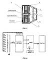
- FIG. 5 is a structural view of a measuring device in accordance with a first embodiment of the invention.
- FIG. 6 is a circuit block diagram of the measuring device in accordance with the first embodiment of the invention.
- FIG. 7 is a structural view of a measuring device in accordance with a second embodiment of the invention.
- FIG. 8 illustrates the position of a sensor in the measuring device in accordance with the second embodiment of the invention.
- FIG. 9 is a circuit block diagram of the measuring device in accordance with the first embodiment of the invention.
- the measuring device of the present invention comprises a gravity acceleration sensor 1 comprising a vertical gravity pendulum unit and a disk capacitive gate sensor; an end face magnetic damping device 2 ; an MCU (microprocessor control unit) data processing unit 3 ; a key-press control unit 4 ; a LCD/LED display unit 5 ; and a housing 6 comprising a supporting and protecting member.
- the vertical gravity pendulum unit of the gravity acceleration sensor 1 has a simple pendulum structure wherein a rotational shaft and a precision bearing act as rotator and supporter.
- An eccentric mass block is used as a pendulum.
- the disk capacitive sensor comprises a moving gate and a fixed gate. The moving gate is connected to the rotational shaft of the simple pendulum, and the fixed gate is connected to the housing 6 .
- the fixed gate When the measuring device is rotating with the rotational shaft of the horizontal screw mechanism, the fixed gate also rotates, while the moving gate of the disk capacitive sensor keeps returning to the vertical position owing to the gravity acting on the pendulum, generating relative rotational angle change between the moving gate and the fixed gate, and thus leading to a change in the coupling capacitance between the moving gate and the fixed gate.
- the pulse equivalent amount corresponding to the relative rotational angle between the moving gate and the fixed gate is obtained by sending an electric signal variation corresponding to the change of the coupling capacitance into the capacitive gate sensor for ASIC processing.
- the output pulse equivalent amount when the relative rotation between the moving gate and the fixed gate has stopped is the pulse equivalent amount corresponding to the change of the rotational angle of the rotational shaft of the screw mechanism.
- the end face magnetic damping device 2 is parallel to the oscillation plane of the pendulum.
- a plurality of thin magnetic slices is circularly disposed along the circumferential edge, and the magnetic poles of adjacent magnetic slices are opposite to each other.
- One face of each magnetic slice is affixed to a magnetic conducting ring; the other face serves to form an air magnetic circuit.
- the pendulum is kept in the air magnetic gap.
- the pendulum When the simple pendulum is oscillating in the gravitational field, the pendulum cuts the magnetic lines of force to generate eddy current, and thereby to form resistance to the oscillating motion of the pendulum.
- the eddy current is proportional to the oscillation speed. Because the oscillation resistance decreases with the decrease of the oscillation speed, the ultimate position of the pendulum is not influenced by the resistance. Contrarily, the oscillation of the pendulum can be stabilized quickly due to the existence of oscillation resistance. Therefore, the pulse equivalent amount of the relative rotation angle between the moving gate and the fixed gate of the capacitive gravity acceleration sensor can reflect rapidly and reliably the relative rotational angle variation of the rotational shaft of the screw mechanism.
- the measuring device of the invention is practical and can be used under oscillating condition of the pendulum.
- the end face magnetic damping device functions in the entire range of 360°.
- the MCU data processing unit 3 processes and converts the pulse equivalent amount of the relative rotation angle between the moving gate and the fixed gate of the capacitive gravity acceleration sensor.
- the lead S is the linear distance the nut advances in one revolution of the screw (in or out).
- the ⁇ value can be calculated by processing and converting the pulse equivalent amount of the relative rotation angle between the moving gate and the fixed gate of the capacitive gravity acceleration sensor.
- the S value is input or selected through key-press control according to the actual value.
- the linear displacement value L is calculated by the above formula, it can be transformed into metric or British system according to demand, and can be coded and digitally output and displayed on the LCD/LED display unit 5 .
- the linear distance can be displayed as 0.61 mm or in inches as 0.02406 inches.
- the linear distance can be displayed as 0.0305 inches or in mm as 0.7761 mm.
- lost motion due to, e.g., play may occur with the screw mechanism.
- the screw mechanism is moving back, such a situation could appear that the rotational shaft has started rotating, but the linear displacement does not start synchronously.
- the capacitive gravity acceleration sensor functions to detect and record the rotation angle variation of the rotational shaft, the obtained linear displacement value based on processing the rotation angle variation would be then inconsistent with the actual back movement linear displacement value.
- a program is included in the program processing of the MCU unit to modify the back movement linear displacement value.
- the actual lost motion deviation value will be measured on site and then be input through key-press control to the program for modifying the displayed value (lost motion calibration), so that the measuring device of the invention is more accurate.
- the housing 6 comprised of supporting and protecting member is designed with electric and magnetic shielding and dust/water protection, so that the capacitive gravity acceleration sensor and the MCU data processing unit are well protected; resistance to vibration, disturbance, and contamination are improved, and the operational stability and reliability of the measuring device are increased.
- the supporting and protecting member is designed with quick assembly and disassembly components, such as magnetic adhesion, quick assembly fitting members, according to demand, to facilitate the installation and maintenance of the measuring device.
- the gravity acceleration sensor comprises a vertical gravity pendulum unit and a disk capacitive sensor.
- This provides the advantages of: 1) wide measuring range, perfect linearity, and multi-turn capability of measurement; 2) applying special integrated circuit (IC) to output digital signal for subsequent processing; 3) magnetic interaction between the moving gate and the fixed gate, free from disturbance to the sensitivity of the vertical gravity pendulum, quick response speed, small temperature difference, low energy consumption, etc.
- IC integrated circuit
- the measuring device of the invention offers more practicality and versatility.
- the gravity acceleration sensor comprises a vertical gravity pendulum unit and a disk capacitive sensor, providing the advantage that the resolution of the disk capacitive sensor can be adjusted according to actual demand. Measuring devices with different manufacturing cost and different precision can be manufactured to satisfy different application requirements. For example, if the sensor is 2-pitch manufactured, then the screw mechanism corresponding to 10 mm lead will have a minimum resolution of 10 ⁇ m; and if the sensor is 18-pitch manufactured, the screw mechanism corresponding to 10 mm lead will have a minimum resolution of 1 ⁇ m.
- the measuring device of the present invention comprises a silicon micro thermocouple type gravity acceleration sensor 1 , a MCU data processing unit 2 , a key-press control unit 3 , a LCD/LED display unit 4 , and a housing 5 comprised of a supporting and protecting member.
- the silicon micro thermocouple type gravity acceleration sensor 1 is an acceleration sensor designed based on MEMS (Micro Electro-Mechanical Systems) technology.
- the function principle of the gravity acceleration sensor 1 is based on the conductance of free convection thermal field.
- the acceleration value is obtained by measuring the variation of internal temperature caused by the acceleration generator.
- the mass block of the sensor is gas, a heat source disposed at the central position of the silicon chip generates a suspending hot air masses in a cavity.
- Four thermal couple sets comprised of aluminum and polycrystalline silicon are disposed symmetrically and equidistantly in the four directions of the heat source.
- the silicon micro thermocouple type gravity acceleration sensor When the silicon micro thermocouple type gravity acceleration sensor is free from acceleration or is disposed horizontally, the temperature decrease gradient is totally symmetric around the heat source. At this point, the voltages resulting from temperature inductance of the four thermocouple sets are identical. Owing to the conductance of the free convection thermal field, the acceleration at any direction can disturb the profile of the heat source, resulting in the asymmetry of the heat source, thus causing output voltage difference between the four thermocouple sets. The difference of the output voltage is proportional directly with the induced acceleration.
- acceleration signal transportation paths inside of the acceleration sensor There are two totally identical acceleration signal transportation paths inside of the acceleration sensor; one path is used for measuring the induced acceleration on X axes, the other path is used for measuring the induced acceleration on Y axes.
- the silicon micro thermocouple type gravity acceleration sensor is disposed vertically, within the rotation range of 360°, one of the gravity acceleration signals measured on X-axes and Y-axes changes from small to large, the other changes from large to small, and alternatively the cycle repeats indefinitely.
- the rotation angle position of the sensor then can be obtained by comparing and processing the signals output from the X-axes and Y-axes through the MCU data processing unit 2 .
- the actual rotation angle of the sensor By detecting the cycle times of the signals on X-axes and Y-axes through the MCU unit, and in combination with the rotation angle position of the sensor, the actual rotation angle of the sensor can be calculated.
- the actual rotation angle of the sensor corresponds to the relative rotation angle variation of the rotational shaft of the screw mechanism.
- the ⁇ value can be calculated according to the signal output on X-axes and Y-axes of the silicon micro thermocouple type gravity acceleration sensor.
- the S value is input or selected through key-press control according to the actual value.
- the linear displacement value L is calculated by the above formula, it can be transformed into metric or British system according to demand, and can be coded and digitally output and displayed on the LCD/LED display unit 4 .
- the linear distance can be displayed as 0.61 mm or in inches as 0.02406 inches.
- the linear distance can be displayed as 0.0305 inches or in mm as 0.7761 mm.
- lost motion due to, e.g., play may occur with the screw mechanism.
- the screw mechanism is moving back, such a situation could appear that the rotational shaft has started rotating, but the linear displacement does not start synchronously.
- the capacitive gravity acceleration sensor functions to detect and record the rotation angle variation of the rotational shaft, the obtained linear displacement value based on processing the rotation angle variation would be then inconsistent with the actual back movement linear displacement value.
- a program is included in the program processing of the MCU unit to modify the back movement linear displacement value.
- the actual lost motion deviation value will be measured on site and then be input through key-press control to the program for modifying the displayed value (lost motion calibration), so that the measuring device of the invention is more accurate.
- the housing 5 comprised of supporting and protecting member is designed with electric and magnetic shielding and dust/water protection, so that the capacitive gravity acceleration sensor and the MCU data processing unit are well protected; resistance to vibration, disturbance, and contamination are improved, and the operational stability and reliability of the measuring device are increased.
- the supporting and protecting member is designed with quick assembly and disassembly components, such as magnetic adhesion, quick assembly fitting members, according to demand, to facilitate the installation and maintenance of the measuring device.
- the gravity acceleration sensor is a silicon micro thermocouple-type gravity acceleration sensor manufactured by applying MEMS technology.
- the manufacturing process is compatible with the conventional integrated circuit (IC), so that it is easy to be integrated with the signal processing circuit. This allows for convenient digitalization and mass production. It also provides the features of compact size, light weight, low cost, and high reliability.
- pulse power supplying can be applied, so that the influence of vibration to the measurement is reduced, and the energy consumption is decreased effectively, contributing to the practicality and versatility of the measuring device.
- the gravity acceleration sensor can be a constant acceleration sensor of a silicon micro capacitive-type, a silicon micro piezoelectric-type, a silicon micro resonant-type, or a silicon micro optical waveguide-type.
- a method for measuring the linear displacement of a screw mechanism comprises processing the sensor signal by the MCU data processing unit, controlling by the key-press control unit, displaying by the display unit, and supporting and protecting by the housing comprised of a supporting and protecting member. This realized the purpose of the devices of Examples 2 and 3.
Landscapes
- Engineering & Computer Science (AREA)
- Power Engineering (AREA)
- Physics & Mathematics (AREA)
- General Physics & Mathematics (AREA)
- Length Measuring Devices With Unspecified Measuring Means (AREA)
- Arrangements For Transmission Of Measured Signals (AREA)
- Transmission Devices (AREA)
Applications Claiming Priority (3)
| Application Number | Priority Date | Filing Date | Title |
|---|---|---|---|
| CN2008100736560A CN101308010B (zh) | 2008-07-01 | 2008-07-01 | 测量水平螺旋传动机构直线位移量的铅垂式数显电子测量装置 |
| CN200810073656.0 | 2008-07-01 | ||
| CN200810073656 | 2008-07-01 |
Publications (2)
| Publication Number | Publication Date |
|---|---|
| US20100004894A1 US20100004894A1 (en) | 2010-01-07 |
| US7930134B2 true US7930134B2 (en) | 2011-04-19 |
Family
ID=40124581
Family Applications (1)
| Application Number | Title | Priority Date | Filing Date |
|---|---|---|---|
| US12/342,124 Active US7930134B2 (en) | 2008-07-01 | 2008-12-23 | Electronic device for measuring motion of screw mechanism |
Country Status (3)
| Country | Link |
|---|---|
| US (1) | US7930134B2 (fr) |
| EP (1) | EP2141462B1 (fr) |
| CN (1) | CN101308010B (fr) |
Families Citing this family (6)
| Publication number | Priority date | Publication date | Assignee | Title |
|---|---|---|---|---|
| CN101819615A (zh) * | 2010-03-15 | 2010-09-01 | 湖南德沐数码科技有限公司 | 一种通过重力加速度保护多媒体产品的方法 |
| CN103809752B (zh) * | 2014-02-12 | 2017-08-29 | 华勤通讯技术有限公司 | 可控制显示位置的便携式终端及其显示方法 |
| CN104931017A (zh) * | 2015-06-19 | 2015-09-23 | 北京送变电公司 | 坡比测量仪 |
| CN108931219B (zh) * | 2018-09-08 | 2024-03-12 | 慈兴集团有限公司 | 滚珠丝杆自动检测装置 |
| CN110793420A (zh) * | 2019-10-23 | 2020-02-14 | 山东理工大学 | 基于螺旋测微原理的高精度位置定位装置 |
| CN115682896B (zh) * | 2023-01-03 | 2023-04-07 | 泉州昆泰芯微电子科技有限公司 | 运动位置检测装置、阀门组件及开度检测方法、管道系统 |
Family Cites Families (3)
| Publication number | Priority date | Publication date | Assignee | Title |
|---|---|---|---|---|
| IT1128168B (it) * | 1980-07-22 | 1986-05-28 | Micrometro Italia Srl | Micrometro a lettura digitale |
| US6171880B1 (en) * | 1999-06-14 | 2001-01-09 | The United States Of America As Represented By The Secretary Of Commerce | Method of manufacture of convective accelerometers |
| CN2854513Y (zh) * | 2005-09-03 | 2007-01-03 | 桂林市晶瑞传感技术有限公司 | 一种便携式数显水平倾角仪 |
-
2008
- 2008-07-01 CN CN2008100736560A patent/CN101308010B/zh active Active
- 2008-12-23 US US12/342,124 patent/US7930134B2/en active Active
-
2009
- 2009-04-29 EP EP09159110.7A patent/EP2141462B1/fr active Active
Non-Patent Citations (1)
| Title |
|---|
| Yaw sensor, BOSCH, Oct. 18, 2001, p. 1-4. * |
Also Published As
| Publication number | Publication date |
|---|---|
| CN101308010B (zh) | 2010-09-29 |
| EP2141462A3 (fr) | 2014-07-02 |
| EP2141462B1 (fr) | 2016-08-10 |
| CN101308010A (zh) | 2008-11-19 |
| US20100004894A1 (en) | 2010-01-07 |
| EP2141462A2 (fr) | 2010-01-06 |
Similar Documents
| Publication | Publication Date | Title |
|---|---|---|
| US7930134B2 (en) | Electronic device for measuring motion of screw mechanism | |
| CN103063189B (zh) | 基于光杠杆的测角器件检定方法 | |
| US10222243B2 (en) | Devices, systems and methods for shifted delta sum angle measurement | |
| CN104501714B (zh) | 汽轮机转子偏心方位角在线监测装置及其监测方法 | |
| JPS63163213A (ja) | 位置検出装置 | |
| CN103048071A (zh) | 用于监测悬浮状态下无框力矩电机动态扭矩的装置及方法 | |
| CN203011370U (zh) | 基于光杠杆的测角器件检定装置 | |
| CN100410667C (zh) | 低转速测量校准仪及校准方法 | |
| JPH08178700A (ja) | インクリメンタルエンコーダ | |
| CN100529662C (zh) | 单轴光纤陀螺寻北仪 | |
| CN104236523A (zh) | 角度检测装置和具有其的倾角传感器 | |
| US4944190A (en) | Flow meter | |
| CN101852581A (zh) | 连续壁厚测量仪及测量方法 | |
| CN105300353B (zh) | 基于过采样技术的高精度倾角测量仪 | |
| CN204301683U (zh) | 汽轮机转子偏心方位角在线监测装置 | |
| JP2977821B1 (ja) | 回転量測定装置 | |
| CN201221937Y (zh) | 测量水平螺旋传动机构直线位移量的铅垂式数显电子测量装置 | |
| CN200975934Y (zh) | 传感器位移校验装置 | |
| JPS63223569A (ja) | 低速気流における風速計の校正方法および装置 | |
| JPH06507492A (ja) | 軸変位測定装置 | |
| CN116358390B (zh) | 一种平面小曲率测量仪器及其使用方法 | |
| CN110988401A (zh) | 一种光电加速度计标定方法及其系统 | |
| CN201672912U (zh) | 连续壁厚测量仪 | |
| SU1756778A2 (ru) | Устройство дл определени моментов газостатических опор | |
| JPS63313007A (ja) | 回転体の軸方向延び量計測装置 |
Legal Events
| Date | Code | Title | Description |
|---|---|---|---|
| AS | Assignment |
Owner name: GUILIN GEMRED SENSOR TECHNOLOGY LTD., CHINA Free format text: ASSIGNMENT OF ASSIGNORS INTEREST;ASSIGNORS:LI, GUANGJIN;SHI, JIAN;REEL/FRAME:025962/0297 Effective date: 20110307 |
|
| STCF | Information on status: patent grant |
Free format text: PATENTED CASE |
|
| FPAY | Fee payment |
Year of fee payment: 4 |
|
| MAFP | Maintenance fee payment |
Free format text: PAYMENT OF MAINTENANCE FEE, 8TH YR, SMALL ENTITY (ORIGINAL EVENT CODE: M2552); ENTITY STATUS OF PATENT OWNER: SMALL ENTITY Year of fee payment: 8 |
|
| MAFP | Maintenance fee payment |
Free format text: PAYMENT OF MAINTENANCE FEE, 12TH YR, SMALL ENTITY (ORIGINAL EVENT CODE: M2553); ENTITY STATUS OF PATENT OWNER: SMALL ENTITY Year of fee payment: 12 |