US7976317B2 - Low profile modular electrical connectors and systems - Google Patents
Low profile modular electrical connectors and systems Download PDFInfo
- Publication number
- US7976317B2 US7976317B2 US11/999,069 US99906907A US7976317B2 US 7976317 B2 US7976317 B2 US 7976317B2 US 99906907 A US99906907 A US 99906907A US 7976317 B2 US7976317 B2 US 7976317B2
- Authority
- US
- United States
- Prior art keywords
- housing
- contact
- plug connector
- plug
- connector
- Prior art date
- Legal status (The legal status is an assumption and is not a legal conclusion. Google has not performed a legal analysis and makes no representation as to the accuracy of the status listed.)
- Active, expires
Links
Images




Classifications
-
- H—ELECTRICITY
- H01—ELECTRIC ELEMENTS
- H01R—ELECTRICALLY-CONDUCTIVE CONNECTIONS; STRUCTURAL ASSOCIATIONS OF A PLURALITY OF MUTUALLY-INSULATED ELECTRICAL CONNECTING ELEMENTS; COUPLING DEVICES; CURRENT COLLECTORS
- H01R12/00—Structural associations of a plurality of mutually-insulated electrical connecting elements, specially adapted for printed circuits, e.g. printed circuit boards [PCB], flat or ribbon cables, or like generally planar structures, e.g. terminal strips, terminal blocks; Coupling devices specially adapted for printed circuits, flat or ribbon cables, or like generally planar structures; Terminals specially adapted for contact with, or insertion into, printed circuits, flat or ribbon cables, or like generally planar structures
- H01R12/70—Coupling devices
- H01R12/7088—Arrangements for power supply
Definitions
- the present invention generally relates to electrical power connectors that are useful as low-profile board-to-board connectors and wire-to-board connectors and that can provide excellent operation under high current density conditions and are particularly suitable for use as modular components within modular assemblies.
- U.S. Pat. No. 4,845,589 which relates to bus bar connectors and addresses undesired effects due to temperature cycling owing to heat generation.
- the patent describes an electrical power connector having two exposed sidewalls that merge with a support structure to form a U-shaped structure. Extending from the two exposed sidewalls are spring contact arms that mate with a bus bar. A sliding structure is provided with the objectives of allowing easy access to the power connector and correcting problems resulting from temperature cycling.
- U.S. Pat. No. 5,618,187 pertains to a bus bar contact for mounting on a circuit board comprising a U-shaped center section, contact fingers, termination posts and stabilizing tabs. The U-shaped center section of the bus bar contact has two exposed parallel panels.
- Pat. No. 6,666,698 describes air gaps between terminals that are susceptible to arcing.
- the patent describes mechanical means which is said to impart higher mating and unmating velocities to diminish arcing in high volt systems.
- U.S. Pat. No. 6,930,889 relates to a circuit board and a slot connector assembly.
- the patent describes a circuit board comprised of a substrate and electrical contacts wherein the electrical contacts mate with contact springs of a slot connector.
- U.S. Pat. No. 6,319,075 pertains to electrical connectors and more particularly to electrical power connectors said to be useful in circuit board or backplane interconnection systems.
- This patent describes electrical terminals comprising a pair of spaced apart planar walls having a bridging structure extending between and joining the walls.
- the bridging structure has forward and rearward bridging elements or a bridging element having an open upper section for heat dissipation.
- U.S. Pat. No. 6,780,027 relates to electrical connectors for transmitting electrical power. This patent is directed to an electrical connector having both an aperture for engagement with a complementary contact and a protruding tab for engagement with an AC cable plug.
- 6,848,950 is directed to power contacts employed in electrical connectors that transmit electrical power.
- the patent describes two-piece electrical contacts having three electrical interfaces. One electrical interface uses the walls of the two pieces to mate with an electrical connector; another interface has terminals or tails extending from the contact to engage a circuit board; and a third interface is a plug projection for engaging a cable plug.
- the patent further describes an electrical connector comprising a first power contact providing both a cable-to-board interface and a board-to-board interface.
- This patent also describes an electrical connector having a power contact with a first wall and a second wall wherein the first wall and the second wall are coupled.
- the electrical connector also has a second power contact with a third wall and a fourth wall wherein the third wall and the fourth wall are uncoupled.
- U.S. Pat. No. 6,848,953 describes an electrical connector, particularly electrical power connectors said to be useful in circuit board or backplane interconnectors.
- the patent discusses a contact with two opposing sidewalls having a bridge extending between the sidewalls and a clip extending from the bridge for engaging the arm of a bus bar.
- U.S. Pat. No. 6,869,294 pertains to matable electrical connectors having power capabilities.
- the patent discloses a plug connector having a substantially U-shaped electrically conductive body. Three open sides and three closed sides define the body. The three closed sides comprise two side walls and an upper bridging element.
- U.S. Pat. No. 6,890,221 pertains to a matable electrical connector in a housing. This approach requires a receptacle connector comprising a pair of spaced receptacle contact walls and a plug connector comprised of a pair of spaced plug contact walls wherein both the receptacle connector and the plug connector are in the same housing.
- 7,059,919 pertains to an electrical connector, particularly electrical power connectors said to be useful in circuit board or backplane interconnectors.
- the patent discusses a pair of flexible beams that extend from a pair of opposed contact side walls.
- the flexible beams are widthwise tapered in a direction from which the beams extend.
- the flexible beams also extend outwardly away from each other and inwardly towards each other.
- An unobstructed heat flow path is defined between the flexible beams.
- U.S. Pat. No. 7,070,464 pertains to electrical connectors, particularly electrical power connectors said to be useful in circuit board or backplane interconnectors.
- the patent describes a pair of opposed contact walls having a bridging element adjoining the opposed contact walls.
- the patent discusses two opposed contact walls each having panels and flexible beams extending from the panels.
- the flexible beams extend outwardly away from each other and inwardly toward each other.
- Prior art including some of that discussed hereinabove describes power connectors that use coupled contacts wherein a cumbersome and restrictive bridging element connects two contacts.
- the bridging elements take up space, restrict air flow and hinder flexible use of contacts.
- the power connector of this invention employing uncoupled contacts has a low profile but sufficient height to provide good air flow within the connectors.
- the power connectors as described herein have low profiles with only slight or moderate temperature rise during extended use.
- board space is saved, the power connectors providing about 30 to about 60 amps per blade and typically about 45 to about 55 amps per blade, equating to between about 120 and about 300 amps per inch and typically between about 180 and about 275 amps per inch.
- the improved power connectors can include plug connectors and receptacle connectors for mating with each other or other components.
- the power connector, the receptacle connector or both may comprise two uncoupled contacts seated in cavities in the housing.
- the contacts have exposed surfaces to dissipate heat resulting from Joule effects, and the cavities are constructed with openings and/or spacings to improve air flow in one or more of the top, bottom, bottom and/or rear of the connector cavities.
- Improved airflow permits higher current density without unacceptable temperature rise and contributes to providing power connectors that have a low profile with no sacrifice of quality or power handling capabilities.
- the use of uncoupled walls eliminates a bridging structure that is used in some prior art approaches to couple and hold two contact walls in position relative to one another.
- the bridging structure typically needs space on the topside of the contact walls adding to the connector height and profile. Eliminating the space required when a bridging structure is included contributes to a lower connector profile.
- the uncoupled contacts can employ small barbs on the sides of the contacts to assist in holding the contacts in place.
- a barb is positioned on a side, such as near the bottom of a contact to ride on a shoulder of the housing and lock in the contact vertically.
- a barb near the top of a contact locks the contact into a housing channel to lock in the contact horizontally.
- Each barb adds little if anything to connector profile. Typically both barb arrangements will be used to provide secure positioning in two dimensions.
- the mating sections of the contacts for the plug connector form a blade structure
- the mating sections of the contacts for the receptacle connector typically have multiple contact beams for parallel path current flow to minimize resistance and heat generation in order to aid in employing higher current densities.
- the multiple contact beams form a receiving section that has camming portions for blade entrance and restriction portions for tight blade contact.
- one mating connector can have guide posts and the other mating connector can have guide apertures to receive the guide posts.
- the guide posts and apertures can be placed on top of the connectors which typically preserves board space or can be placed the side of the connectors for enhanced air flow.
- FIG. 1 is a perspective view, partially broken away, of an embodiment of a plug connector coupled to a receptacle connector;
- FIG. 1A is a perspective view of a contact pair of the plug connector shown in FIG. 1 ;
- FIG. 1B is a side elevational view of a contact as in FIG. 1A ;
- FIG. 2 is a perspective view of another embodiment of a plug contact having two uncoupled plug contact members
- FIG. 3 is a detailed perspective view of the plug connector of FIG. 1 , shown connected with a printed circuit board;
- FIG. 4 is a detailed elevational view of the plug connector of FIG. 1 , showing engagement and spacing between the contact and components of the housing;
- FIG. 5 is a perspective view of a plug connector and of an embodiment of a receptacle connector, partially broken away, such as shown in FIG. 1 ;
- FIG. 5A is a perspective view of an embodiment of an uncoupled receptacle contact pair
- FIG. 5B is a side elevational view of a receptacle contact member of the contact pair as in FIG. 5 ;
- FIG. 5C is a top plan view of an uncoupled receptacle contact pair as in FIG. 5 ;
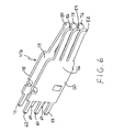
- FIG. 6 is a perspective view or another embodiment of a receptacle contact pair, showing two uncoupled receptacle contact members
- FIG. 7 is a perspective view of a plug connector having a plurality of plug contacts in an insulative housing
- FIG. 7A is a perspective view, partially broken away, of the edges of plug contacts in insulative housing
- FIG. 8 is a perspective view of a plug connector and of a receptacle connector with receptacle contacts in insulative housing, partially broken away, the receptacle contacts shown in engagement with blades of the plug connector;
- FIG. 8A is a perspective view of the receptacle connector of FIG. 8 , rotated 180 degrees, showing receptacle contacts in an insulative receptacle housing;
- FIG. 8B is a perspective view of embodiments of contacts shown in a mated configuration, with the respective housings being removed to provide more detailed views of uncoupled panels in both contacts seen in FIG. 8 ;
- FIG. 9 is a perspective view of an embodiment including an assembly of various modular components including a plug connector and a receptacle connector connected to a printed circuit board;
- FIG. 10 is another, differently oriented perspective view of the assembly embodiment illustrated in FIG. 9 ;
- FIG. 11 is an exploded perspective view of another orientation of the assembly embodiment illustrated in FIG. 9 ;
- FIG. 12 is a perspective view of one of the exploded assemblies of FIG. 11 , at another different orientation;
- FIG. 13 is a perspective view of two modules from FIG. 9 , illustrating a dovetail assembly embodiment
- FIG. 14 is another perspective view of an embodiment of modular components as generally shown in FIG. 13 ;
- FIG. 15 is a perspective view of another embodiment including a modular receptacle connector assembly coupled to a modular plug connector assembly;
- FIG. 16 is a side elevation view of the modular receptacle connector assembly shown in FIG. 15 ;
- FIG. 17 is a top plan view of another embodiment of a modular receptacle connector assembly.
- FIG. 1 illustrates a plug connector, generally designated at 10 , and a receptacle connector, generally designated at 11 . These are suitable for use as power connector components.
- the term power connector is meant to encompass AC power connectors and/or DC power connectors.
- the plug connector 10 illustrated in FIG. 1 includes a contact, generally designated at 13 , comprising a pair of mechanically uncoupled contact members, generally designated at 14 and 15 .
- the contact 13 is held in place by a plug connector insulative housing 17 , cut away at some of the contacts shown in this FIG. 1 .
- Contact members 14 and 15 have back panels or body panels 18 and 20 , respectively. Panels 18 and 20 are substantially parallel to each other and form a medial space 16 between them. As seen in FIGS.
- PCB printed circuit board
- beams 42 and 44 are also extending from back panels or body panels 18 and 20 .
- beams 42 and 44 which are mechanically uncoupled and extend from sides of the panels 18 and 20 that are orthogonal to the sides of panels 18 and 20 from which the tails extend.
- the tails in this embodiment are typically solder tails and compliant tails.
- These contact members include back or body panels 18 a and 20 a , which have tails 21 , 23 , 25 and 27 and tails 31 , 33 , 35 and 37 , respectively, that extend from these back panels in a direction generally opposite to or in line with the respective beams 42 and 44 .
- the tails in this embodiment typically are solder tails and compliant tails.
- the blade extends from back panel or body panel pairs or contact members 18 , 20 or 18 a , 20 a .
- beams 42 and 44 extend from the back or body panels first in an inward direction toward each other until they meet, and then they are parallel to each other, typically in contact with each other along this length.
- the outwardly extending section of the beams 42 and 44 form blade 46 , which is the mating portion of the contacts 13 of the plug connector 10 . As seen in FIGS.
- barbs 117 and 120 can be provided to cooperate with members of the housing such as housing shoulders or projections 118 , to maintain the contact members 14 , 15 in place and/or to provide housing channel 116 or open volume 119 along a face of a contact member.
- Receptacle connector generally designated at 11 in FIG. 1 and with its housing removed in FIG. 5 , has contacts, generally designated at 47 , each having two spaced apart uncoupled contact members 48 and 50 forming a medial space 52 between contact members 48 and 50 .
- Contacts members 48 and 50 have back panels or body panels 54 and 56 , respectively, that are substantially parallel to each other. Extending from the bottom of panels 54 and 56 are tails 57 , 59 , 61 , 63 and 65 and tails 66 , 68 , 70 , 72 and 74 , respectively, for insertion into a PCB. After insertion, the tails may be soldered in place. Also extending from panels 54 and 56 are beams 76 , 78 and 80 and beams 82 , 84 and 86 , respectively.
- beams 76 , 78 and 80 and beams 82 , 84 and 86 extend from respective edges of the back panels or body panels 54 and 56 that are orthogonal to the edges of panels 54 and 56 from which the tails extend.
- the tails of this embodiment typically are solder tails or compliant tails. This orthogonal relative orientation of the beams and tails is used for parallel board connection.
- FIG. 5 illustrates that beams 76 , 78 and 80 and beams 82 , 84 and 86 extend from respective edges of the back panels or body panels 54 and 56 that are orthogonal to the edges of panels 54 and 56 from which the tails extend.
- the tails of this embodiment typically are solder tails or compliant tails. This orthogonal relative orientation of the beams and tails is used for parallel board connection.
- a contact is provided, generally designated as contact 47 a
- the beams 76 , 78 and 80 and beams 82 , 84 and 86 extend from respective edges of panels 54 and 56 that are opposite of the edges of panels 54 and 56 from which tails 67 , 69 and 71 , and tails 58 , 60 and 62 extend, respectively.
- the tails in this embodiment are typically solder tails or compliant tails. This opposing relative orientation of the beams and tails is used for perpendicular board connection, where one board can be considered a horizontal board and the other a vertical board.
- the beams extend from the back panels or body panels 54 , 56 .
- beams 76 , 78 and 80 and beams 82 , 84 and 86 first extend from the respective panels 54 and 56 inwardly toward the opposing beam of the opposing contact and then outwardly away from the opposing beam.
- the sections of the opposing beams that extend outwardly form camming surfaces 88 and 90 first contact a plug connector during mating. In an illustrated embodiment, the camming surfaces 88 , 90 engage blade 46 of the plug connector 10 .
- plug connector 10 includes insulative plug housing 96 that has a top wall 100 , a front wall 102 and side walls 104 .
- Housing 96 also has one or more tunnel like cavities 98 that extend through the back and bottom of housing 96 and extend close to but not through top wall 100 , front wall 102 and sidewall 104 .
- Front wall 102 has aperture 106 at each section that is large enough for blade 46 to pass through.
- Front wall 102 also has two smaller apertures 108 at each section that allow for probes to be inserted into housing 96 .
- Front wall 102 in addition has an indentation 110 at each section that extends from top to bottom and forms a top aperture 112 and a bottom aperture 114 therealong.
- a housing channel 116 and a housing shoulder or projection 118 in housing 96 assist in positioning each pair of contact members 14 and 15 .
- Contact members 14 and 15 are spaced apart from side walls of cavities 98 .
- a side barb or projecting member 117 on one or both of contact members 14 and 15 is shown, for example in FIG. 3 , toward the bottom of the panels riding on housing shoulder 118 to lock contact members 14 and 15 vertically while providing air space around the contact members.
- Contact members 14 and 15 are positioned slightly above a board component such as PCB 148 shown in FIG. 3 when in use to assist in providing a slight spacing 150 from the PCB or the like. Such spacing assists with proper solder flow while also providing air volume for heat dissipation and typically is facilitated by providing standoffs 115 .
- This illustrated plug connector embodiment also provides a barb or a projecting member 120 on each or both of contact members 14 and 15 , as shown for example in FIG. 1A .
- Each such barb or member 120 fits within housing channel 116 and engages wall 121 ( FIG. 4 ) of housing 17 to prevent horizontal movement of contact members 14 and 15 within the connector housing 96 . Maintaining proper positioning helps to assure correct alignment and air space around the contact members, and same can contribute to reducing size requirements.
- the housing shoulders and the housing channels can be positioned such that housing 96 is positioned slightly above the PCB so there exists a slight space between housing 96 and the PCB, typically with the assistance of the standoff 115 as noted herein.
- receptacle connector 11 has insulative receptacle housing, generally designated at 122 , that has a top wall 124 , a front wall 126 and side walls 128 .
- Housing 122 also has one or more tunnel like cavities 130 , typically one at each section, that extend through the back and bottom of housing 122 and extend close to but not through top wall 124 , front wall 126 and side walls 128 .
- Front wall 126 has aperture 132 at each section just large enough for blade 46 from plug connector 10 and only minimal air to pass through.
- Housing channel or top slots 134 and housing shoulder or projection 136 position contact members 48 and 50 in each section of housing 122 .
- Contacts 47 comprised of contact members 48 and 50 are spaced apart from side walls of cavities 130 at each section. Barbs 137 are shown in this illustrated embodiment on contact members 48 and 50 , as shown in FIG. 8B , ride on housing shoulder 136 and lock contact members 48 and 50 vertically. Contact members 48 and 50 are positioned slightly above the PCB when in use to assist in providing clearance from the PCB. Such typically is facilitated by including at least one standoff 139 .
- This illustrated receptacle connector embodiment also provides a barb 138 in one or each of contact members 48 and 50 that fits within housing channel 134 at each section to prevent horizontal movement of contact members 48 and 50 within housing 122 , while providing air space around the contact members 48 and 50 .
- the contact barbs, the housing shoulders and the housing channels can be positioned such that housing 122 is positioned slightly above the PCB 148 so there exists a slight space between housing 122 and the PCB.
- FIG. 8B shows a typical mating engagement between plug contact 13 and receptacle contact 47 and provides an unobstructed view of an embodiment of these components.
- a plug connector 10 and a receptacle connector 11 shown in a power connector assembly 152 , can be used in a modular manner by placing complementary interlocking connectors such as interlocking dove tails 140 and 142 on respective outer sides of the plug housing and on respective outer sides of the receptacle housing.
- This modular housing approach provides product flexibility with ease of manufacturing and low tooling cost.
- signal connectors generally designated as 154 , 156
- Multiple signal modules and power modules can be assembled to provide a power connector assembly, with or without signal modules.
- guide posts 144 on the housing of the plug connector 10 and guide post receptors 146 on the housing of the receptacle connector 11 may optionally be used for ease of mating.
- One or more guide posts can be added with corresponding guide post receptors to further aid in alignment and mating.
- the guide post and post receptors system will incorporate dovetails 140 a and 142 a .
- FIG. 15 represents a modular connector system, generally designated as 210 , that comprises a modular receptacle connector assembly, generally designated as 211 , and a modular plug connector assembly, generally designated as 212 .
- Modular plug assembly 212 is shown connecting PCB or mother board 215 , considered horizontal, to PCB or daughter board 217 , considered to be vertical.
- Modular connector system 210 is thus shown as one modular piece that connects two PCBs at a right angle.
- FIG. 16 illustrates receptacle connector assembly 211 comprised of three interconnected modules, power receptacle module for DC input power, generally designated as 221 , receptacle module for electrical signal, generally designated as 223 , and receptacle module for DC ground return, generally designated as 225 .
- DC power receptacle module 221 has insulative housing 208 .
- DC power receptacle module 221 has a plurality of cavities 228 in housing 208 to seat DC power receptacle contacts 230 ( FIG. 16 ).
- DC power input of power receptacle module 221 as shown in FIG. 16 suitably comprises one set of contacts to provide one DC power supply.
- Said DC power supply provides between about 500 and about 2200 watts and typically between about 800 and about 1500 watts, with the current divided substantially equally over the input contacts.
- the DC receptacle contacts have a pitch of about 6.0 mm.
- Signal module 223 has insulative housing 164 and suitably contains between about 6 and about 40 mated signal contacts and typically between about 18 and about 32 signal receptacle contacts 166 .
- Side 170 of signal receptacle housing 164 interconnects to side 172 of power input receptacle housing 208 , as shown in FIG. 16 .
- Side 170 and side 172 have mating dove tail members 174 and 176 .
- This modular housing approach provides product flexibility with ease of manufacturing and low tooling cost.
- Secondary interlocking features such as clips 178 ( FIG. 16 ) at the bottom of the module 223 are also employed to aid in proper alignment of the modules and increase the strength of the interlock. All side by side aligned modules in modular connector system 210 may be interlocked employing these features.
- DC ground return receptacle module 225 ( FIG. 16 ) has insulative housing 180 with cavities 181 for seating DC ground receptacle contacts 182 .
- These DC ground receptacle contacts transmit ground power return of about 500 to about 2200 watts and typically between about 800 and about 1500 watts, and the current is divided substantially equally among the ground receptacle contacts.
- the contacts Opposite the mating portion of the ground return receptacle contacts, the contacts have a plurality of compliant pins for insertion into a board considered to be vertical.
- DC power input receptacle contacts 230 and DC ground return receptacle contacts 182 align substantially in a row.
- DC power plug module 214 has insulative housing 234 with cavities 235 to seat DC power plug contacts 236 .
- Electrical signal plug module 216 has signal plug housing 248 that incorporates between about 6 and about 40 mated signal contacts and typically between about 18 and about 32 signal contacts.
- DC ground module 218 has insulative housing 252 with cavities 254 to seat DC ground plug contacts 256 .
- Guide posts 264 and 266 ( FIG. 17 ) on the housing of the plug modules 214 and 218 , respectively, and guide post receptors 268 and 270 ( FIG. 16 ) on the housing of the receptacle modules 221 and 225 , respectively, may optionally be used for ease of mating.
- One or more guide posts can be added with corresponding guide post receptors to further aid in alignment and mating. When the guide posts and receptors are added to the tops of modules, this helps to preserve board space such as by minimizing width.
- modular connector system 210 shown in FIG. 15 has a height of between about 12 and about 25 mm off the board and typically between about 18 and about 22 mm off the board.
Landscapes
- Coupling Device And Connection With Printed Circuit (AREA)
Priority Applications (4)
| Application Number | Priority Date | Filing Date | Title |
|---|---|---|---|
| US11/999,069 US7976317B2 (en) | 2007-12-04 | 2007-12-04 | Low profile modular electrical connectors and systems |
| TW097145912A TWI392157B (zh) | 2007-12-04 | 2008-11-27 | 低輪廓模組化電氣連接器及系統 |
| CN2008901003113U CN201829645U (zh) | 2007-12-04 | 2008-12-03 | 连接器 |
| PCT/US2008/085358 WO2009073695A1 (fr) | 2007-12-04 | 2008-12-03 | Connecteurs et systèmes électriques modulaires à profil bas |
Applications Claiming Priority (1)
| Application Number | Priority Date | Filing Date | Title |
|---|---|---|---|
| US11/999,069 US7976317B2 (en) | 2007-12-04 | 2007-12-04 | Low profile modular electrical connectors and systems |
Publications (2)
| Publication Number | Publication Date |
|---|---|
| US20090142953A1 US20090142953A1 (en) | 2009-06-04 |
| US7976317B2 true US7976317B2 (en) | 2011-07-12 |
Family
ID=40342806
Family Applications (1)
| Application Number | Title | Priority Date | Filing Date |
|---|---|---|---|
| US11/999,069 Active 2028-01-10 US7976317B2 (en) | 2007-12-04 | 2007-12-04 | Low profile modular electrical connectors and systems |
Country Status (4)
| Country | Link |
|---|---|
| US (1) | US7976317B2 (fr) |
| CN (1) | CN201829645U (fr) |
| TW (1) | TWI392157B (fr) |
| WO (1) | WO2009073695A1 (fr) |
Cited By (24)
| Publication number | Priority date | Publication date | Assignee | Title |
|---|---|---|---|---|
| US20120149217A1 (en) * | 2009-05-20 | 2012-06-14 | Molex Incorporated | Board-to-board connector |
| US20120164892A1 (en) * | 2010-12-27 | 2012-06-28 | Chief Land Electronic Co., Ltd. | Power connector assembly with improved terminals |
| US20140065899A1 (en) * | 2011-05-13 | 2014-03-06 | Tyco Electronics Amp Gmbh | Plug Contact Modules and Plug Contact Arrangement For Transmitting Frequencies in the Gigahertz Range |
| US20140127949A1 (en) * | 2012-11-08 | 2014-05-08 | Alltop Electronics (Suzhou) Ltd. | Electrical connector with improved contact |
| US20140127945A1 (en) * | 2012-11-08 | 2014-05-08 | Alltop Electronics (Suzhou), Ltd | Electrical connector with improved retention structure |
| US20140377967A1 (en) * | 2013-06-25 | 2014-12-25 | Alltop Electronics (Suzhou), Ltd. | Electrical connector with improved contact structure |
| US20150357734A1 (en) * | 2013-03-14 | 2015-12-10 | Fci Americas Technology Llc | Flexible power connector |
| US20160013570A1 (en) * | 2014-07-11 | 2016-01-14 | Rupert Fry, JR. | Orthogonal electrical connector system |
| US20160064872A1 (en) * | 2014-09-02 | 2016-03-03 | BizConn International Corp. | Large current female connector for high-speed transmission |
| US9385500B2 (en) | 2013-08-26 | 2016-07-05 | FCI Asia Pte. Ltd. | Electrical connector including fins |
| US9401558B1 (en) * | 2015-01-30 | 2016-07-26 | Alltop Electronics (Suzhou) Ltd. | Power connector |
| US20160295082A1 (en) * | 2015-03-31 | 2016-10-06 | Canon Kabushiki Kaisha | Apparatus body of image pickup apparatus and lens adapter for equipping interchangeable lens to apparatus body |
| US20170006733A1 (en) * | 2013-12-17 | 2017-01-05 | Molex, Llc | Power connector |
| US9774157B2 (en) | 2013-07-12 | 2017-09-26 | Molex, Llc | Power connector |
| US9853388B2 (en) * | 2013-11-27 | 2017-12-26 | Fci Americas Technology Llc | Electrical power connector |
| US20180219332A1 (en) * | 2017-01-30 | 2018-08-02 | Fci Usa Llc | Multi-piece power connector with cable pass through |
| US20190020142A1 (en) * | 2017-01-24 | 2019-01-17 | Alltop Electronics (Suzhou) Ltd. | Power connector |
| US10522945B2 (en) * | 2016-08-22 | 2019-12-31 | Interplex Industries, Inc. | Electrical connector |
| US10741945B2 (en) | 2013-08-26 | 2020-08-11 | Fci Usa Llc | Replacement electrical connectors |
| US10763607B2 (en) | 2016-08-22 | 2020-09-01 | Interplex Industries, Inc. | Electrical connector |
| US11095056B2 (en) * | 2019-11-04 | 2021-08-17 | Dongguan Luxshare Technologies Co., Ltd. | Electrical connector with reduce distance between electrical terminals |
| US11539154B2 (en) * | 2020-07-21 | 2022-12-27 | Te Connectivity Solutions Gmbh | Power contact for electrical connector |
| US12176637B2 (en) | 2021-02-09 | 2024-12-24 | Fci Usa Llc | Electrical connector for high power computing system |
| US12401146B2 (en) | 2019-12-12 | 2025-08-26 | Fci Usa Llc | Card-edge connector system with busbar connection for high-power applications |
Families Citing this family (28)
| Publication number | Priority date | Publication date | Assignee | Title |
|---|---|---|---|---|
| US8435043B2 (en) * | 2008-08-13 | 2013-05-07 | Alltop Electronics (Suzhou) Co., Ltd | Power connector assembly |
| CH699404A1 (de) * | 2008-08-25 | 2010-02-26 | Josef Martin Gmbh & Co Kg | Energieträgerkupplung, sowie Kupplung mit Energieträgerkupplung. |
| USD664096S1 (en) | 2009-01-16 | 2012-07-24 | Fci Americas Technology Llc | Vertical electrical connector |
| USD610548S1 (en) | 2009-01-16 | 2010-02-23 | Fci Americas Technology, Inc. | Right-angle electrical connector |
| USD606497S1 (en) | 2009-01-16 | 2009-12-22 | Fci Americas Technology, Inc. | Vertical electrical connector |
| US7677919B1 (en) * | 2009-02-09 | 2010-03-16 | Tai Twun Enterprise Co., Ltd. | Battery connector |
| CN201601287U (zh) * | 2009-09-04 | 2010-10-06 | 富士康(昆山)电脑接插件有限公司 | 电连接器 |
| US7963810B1 (en) * | 2010-01-28 | 2011-06-21 | Cheng Uei Precision Industry Co., Ltd. | Electrical connector |
| US8425237B2 (en) | 2010-09-11 | 2013-04-23 | International Business Machines Corporation | Socket having heat-dissipating vents |
| JP5041563B1 (ja) * | 2011-06-27 | 2012-10-03 | 日本航空電子工業株式会社 | コネクタ、コネクタ装置および電池ユニット |
| JP2013182878A (ja) * | 2012-03-05 | 2013-09-12 | Yazaki Corp | 電子部品の接続構造 |
| US9301025B2 (en) * | 2013-03-07 | 2016-03-29 | Telect, Inc. | Removable sensor modules |
| US9680236B2 (en) | 2013-07-08 | 2017-06-13 | Fci Americas Technology Llc | Electrical connector |
| DE102013111571B4 (de) * | 2013-10-21 | 2016-11-17 | Wago Verwaltungsgesellschaft Mbh | Gerätegehäuse, Elektronikgeräte und Steckkontaktträger |
| US9780517B2 (en) * | 2013-12-23 | 2017-10-03 | Amphenol Fci Asia Pte Ltd | Electrical connector |
| CN104485533A (zh) * | 2014-12-29 | 2015-04-01 | 苏州华旃航天电器有限公司 | 一种电源连接器的插座 |
| CN110679042B (zh) * | 2017-08-02 | 2023-01-17 | 阿维科斯公司 | 将第一电线与第二电线连接的设备和方法 |
| BE1025701B1 (de) | 2017-11-10 | 2019-06-11 | Phoenix Contact Gmbh & Co. Kg | Buchsenlötkontakt und Kontaktmodul für eine Leiterplatte |
| DE102017220022B4 (de) * | 2017-11-10 | 2019-05-29 | Phoenix Contact Gmbh & Co. Kg | Buchsenlötkontakt und Kontaktmodul für eine Leiterplatte |
| US10879647B2 (en) | 2018-03-16 | 2020-12-29 | Fci Usa Llc | Double pole power connector |
| USD975024S1 (en) | 2019-04-12 | 2023-01-10 | Fci Connectors Dongguan Ltd. | Electrical connector |
| CN111817067A (zh) | 2019-04-12 | 2020-10-23 | 富加宜连接器(东莞)有限公司 | 电连接器、电连接器组件、电设备和电互连系统 |
| EP3761763A1 (fr) * | 2019-07-03 | 2021-01-06 | Schaffner EMV AG | Filtre avec ensemble de barre de bus |
| US11811159B2 (en) | 2020-03-27 | 2023-11-07 | Sung-Yu Chen | Terminal with leaf spring extending rearward from support at both side walls |
| CN214478325U (zh) * | 2020-03-27 | 2021-10-22 | 陈松佑 | 具分流结构的电连接器及分流装置 |
| TWM646549U (zh) * | 2021-10-29 | 2023-10-01 | 美商Fci美國有限責任公司 | 低輪廓電連接器 |
| CN119381802A (zh) * | 2023-07-26 | 2025-01-28 | 东莞立讯技术有限公司 | 电源连接器 |
| TWM652227U (zh) * | 2023-08-04 | 2024-03-01 | 大陸商歐品電子(昆山)有限公司 | 電源連接器及電源端子組件 |
Citations (23)
| Publication number | Priority date | Publication date | Assignee | Title |
|---|---|---|---|---|
| US3596235A (en) | 1968-08-22 | 1971-07-27 | Amp Inc | Electrical contact element and an electrical connector and an electrical connector assembly comprising the contact element |
| US4790763A (en) | 1986-04-22 | 1988-12-13 | Amp Incorporated | Programmable modular connector assembly |
| US4845589A (en) | 1987-05-04 | 1989-07-04 | Amp Incorporated | Bus bar connector assembly |
| US4881905A (en) | 1986-05-23 | 1989-11-21 | Amp Incorporated | High density controlled impedance connector |
| US5221210A (en) * | 1991-04-02 | 1993-06-22 | Amp Incorporated | Circuite board connector |
| WO1996013879A1 (fr) | 1994-10-28 | 1996-05-09 | Tvm, Inc. | Systeme de connecteur electrique modulaire hybride |
| US5584728A (en) | 1994-11-25 | 1996-12-17 | Hon Hai Precision Ind. Co., Ltd. | Modular connector assembly with variably positioned units |
| US5618187A (en) | 1994-11-17 | 1997-04-08 | The Whitaker Corporation | Board mount bus bar contact |
| US5667392A (en) | 1995-03-28 | 1997-09-16 | The Whitaker Corporation | Electrical connector with stabilized contact |
| US5951306A (en) | 1996-03-29 | 1999-09-14 | The Whitaker Corporation | Modular connector assembly |
| EP0951102A2 (fr) | 1998-04-17 | 1999-10-20 | Berg Electronics Manufacturing B.V. | Connecteur de puissance |
| US6059615A (en) | 1997-01-31 | 2000-05-09 | Berg Technology, Inc. | Modular cable to board power connector |
| US6299492B1 (en) * | 1998-08-20 | 2001-10-09 | A. W. Industries, Incorporated | Electrical connectors |
| US6402566B1 (en) * | 1998-09-15 | 2002-06-11 | Tvm Group, Inc. | Low profile connector assembly and pin and socket connectors for use therewith |
| US6666698B2 (en) | 2000-08-17 | 2003-12-23 | Tyco Electronics Corporation | Arc limiting electrical connector assembly |
| US6780027B2 (en) | 2003-01-28 | 2004-08-24 | Fci Americas Technology, Inc. | Power connector with vertical male AC power contacts |
| US6814590B2 (en) | 2002-05-23 | 2004-11-09 | Fci Americas Technology, Inc. | Electrical power connector |
| US6848953B2 (en) | 1998-04-17 | 2005-02-01 | Fci Americas Technology, Inc. | Power connector |
| US6848950B2 (en) * | 2003-05-23 | 2005-02-01 | Fci Americas Technology, Inc. | Multi-interface power contact and electrical connector including same |
| US6890221B2 (en) | 2003-01-27 | 2005-05-10 | Fci Americas Technology, Inc. | Power connector with male and female contacts |
| US6930889B2 (en) | 2001-03-16 | 2005-08-16 | Intel Corporation | Circuit board and slot connector assembly |
| US6969268B2 (en) | 2002-06-11 | 2005-11-29 | Molex Incorporated | Impedance-tuned terminal contact arrangement and connectors incorporating same |
| US20060166536A1 (en) | 1998-04-17 | 2006-07-27 | Northey William A | Electrical power connector |
Family Cites Families (5)
| Publication number | Priority date | Publication date | Assignee | Title |
|---|---|---|---|---|
| US5281762A (en) * | 1992-06-19 | 1994-01-25 | The Whitaker Corporation | Multi-conductor cable grounding connection and method therefor |
| US6380485B1 (en) * | 2000-08-08 | 2002-04-30 | International Business Machines Corporation | Enhanced wire termination for twinax wires |
| US6489563B1 (en) * | 2001-10-02 | 2002-12-03 | Hon Hai Precision Ind. Co., Ltd. | Electrical cable with grounding sleeve |
| JP2006054102A (ja) * | 2004-08-11 | 2006-02-23 | Jst Mfg Co Ltd | コネクタ及びケーブル保持部材 |
| TWM319540U (en) * | 2007-03-13 | 2007-09-21 | Alltop Technology Co Ltd | Improved terminal structure of power connector |
-
2007
- 2007-12-04 US US11/999,069 patent/US7976317B2/en active Active
-
2008
- 2008-11-27 TW TW097145912A patent/TWI392157B/zh active
- 2008-12-03 WO PCT/US2008/085358 patent/WO2009073695A1/fr not_active Ceased
- 2008-12-03 CN CN2008901003113U patent/CN201829645U/zh not_active Expired - Lifetime
Patent Citations (33)
| Publication number | Priority date | Publication date | Assignee | Title |
|---|---|---|---|---|
| US3596235A (en) | 1968-08-22 | 1971-07-27 | Amp Inc | Electrical contact element and an electrical connector and an electrical connector assembly comprising the contact element |
| US4790763A (en) | 1986-04-22 | 1988-12-13 | Amp Incorporated | Programmable modular connector assembly |
| US4881905A (en) | 1986-05-23 | 1989-11-21 | Amp Incorporated | High density controlled impedance connector |
| US4845589A (en) | 1987-05-04 | 1989-07-04 | Amp Incorporated | Bus bar connector assembly |
| US5221210A (en) * | 1991-04-02 | 1993-06-22 | Amp Incorporated | Circuite board connector |
| WO1996013879A1 (fr) | 1994-10-28 | 1996-05-09 | Tvm, Inc. | Systeme de connecteur electrique modulaire hybride |
| US5575690A (en) * | 1994-10-28 | 1996-11-19 | Tvm, Inc. | Hybrid modular electrical connector system |
| US5618187A (en) | 1994-11-17 | 1997-04-08 | The Whitaker Corporation | Board mount bus bar contact |
| US5584728A (en) | 1994-11-25 | 1996-12-17 | Hon Hai Precision Ind. Co., Ltd. | Modular connector assembly with variably positioned units |
| US5667392A (en) | 1995-03-28 | 1997-09-16 | The Whitaker Corporation | Electrical connector with stabilized contact |
| US5951306A (en) | 1996-03-29 | 1999-09-14 | The Whitaker Corporation | Modular connector assembly |
| US6059615A (en) | 1997-01-31 | 2000-05-09 | Berg Technology, Inc. | Modular cable to board power connector |
| US20050136713A1 (en) | 1998-04-17 | 2005-06-23 | Schell Mark S. | Power connector |
| US6869294B2 (en) * | 1998-04-17 | 2005-03-22 | Fci Americas Technology, Inc. | Power connector |
| US6319075B1 (en) | 1998-04-17 | 2001-11-20 | Fci Americas Technology, Inc. | Power connector |
| US20060194481A1 (en) | 1998-04-17 | 2006-08-31 | Fci Americas Technology, Inc. | Power connector |
| EP0951102A2 (fr) | 1998-04-17 | 1999-10-20 | Berg Electronics Manufacturing B.V. | Connecteur de puissance |
| US7059919B2 (en) | 1998-04-17 | 2006-06-13 | Fci Americas Technology, Inc | Power connector |
| US7374436B2 (en) * | 1998-04-17 | 2008-05-20 | Fci Americas Technology, Inc. | Power connector |
| US20060166536A1 (en) | 1998-04-17 | 2006-07-27 | Northey William A | Electrical power connector |
| US6848953B2 (en) | 1998-04-17 | 2005-02-01 | Fci Americas Technology, Inc. | Power connector |
| US7070464B2 (en) | 1998-04-17 | 2006-07-04 | Fci Americas Technology, Inc. | Power connector |
| US6299492B1 (en) * | 1998-08-20 | 2001-10-09 | A. W. Industries, Incorporated | Electrical connectors |
| US6604967B2 (en) | 1998-09-15 | 2003-08-12 | Tyco Electronics Corporation | Socket assembly and female connector for use therewith |
| US6402566B1 (en) * | 1998-09-15 | 2002-06-11 | Tvm Group, Inc. | Low profile connector assembly and pin and socket connectors for use therewith |
| US6666698B2 (en) | 2000-08-17 | 2003-12-23 | Tyco Electronics Corporation | Arc limiting electrical connector assembly |
| US6930889B2 (en) | 2001-03-16 | 2005-08-16 | Intel Corporation | Circuit board and slot connector assembly |
| US7168963B2 (en) | 2002-05-23 | 2007-01-30 | Fci Americas Technology, Inc. | Electrical power connector |
| US6814590B2 (en) | 2002-05-23 | 2004-11-09 | Fci Americas Technology, Inc. | Electrical power connector |
| US6969268B2 (en) | 2002-06-11 | 2005-11-29 | Molex Incorporated | Impedance-tuned terminal contact arrangement and connectors incorporating same |
| US6890221B2 (en) | 2003-01-27 | 2005-05-10 | Fci Americas Technology, Inc. | Power connector with male and female contacts |
| US6780027B2 (en) | 2003-01-28 | 2004-08-24 | Fci Americas Technology, Inc. | Power connector with vertical male AC power contacts |
| US6848950B2 (en) * | 2003-05-23 | 2005-02-01 | Fci Americas Technology, Inc. | Multi-interface power contact and electrical connector including same |
Non-Patent Citations (1)
| Title |
|---|
| International Search Report for PCT/US2008/085358. |
Cited By (39)
| Publication number | Priority date | Publication date | Assignee | Title |
|---|---|---|---|---|
| US8888505B2 (en) * | 2009-05-20 | 2014-11-18 | Molex Incorporated | Board-to-board connector |
| US20120149217A1 (en) * | 2009-05-20 | 2012-06-14 | Molex Incorporated | Board-to-board connector |
| US20120164892A1 (en) * | 2010-12-27 | 2012-06-28 | Chief Land Electronic Co., Ltd. | Power connector assembly with improved terminals |
| US8262395B2 (en) * | 2010-12-27 | 2012-09-11 | Chief Land Electronic Co., Ltd. | Power connector assembly with improved terminals |
| US20140065899A1 (en) * | 2011-05-13 | 2014-03-06 | Tyco Electronics Amp Gmbh | Plug Contact Modules and Plug Contact Arrangement For Transmitting Frequencies in the Gigahertz Range |
| US9548552B2 (en) * | 2011-05-13 | 2017-01-17 | Te Connectivity Germany Gmbh | Plug contact modules and plug contact arrangement for transmitting frequencies in the gigahertz range |
| US8932082B2 (en) * | 2012-11-08 | 2015-01-13 | Alltop Electronics (Suzhou) Ltd. | Electrical connector with improved retention structure |
| US20140127945A1 (en) * | 2012-11-08 | 2014-05-08 | Alltop Electronics (Suzhou), Ltd | Electrical connector with improved retention structure |
| US9054448B2 (en) * | 2012-11-08 | 2015-06-09 | Alltop Electronics (Suzhou) Ltd. | Electrical connector with improved contact |
| US20140127949A1 (en) * | 2012-11-08 | 2014-05-08 | Alltop Electronics (Suzhou) Ltd. | Electrical connector with improved contact |
| US20150357734A1 (en) * | 2013-03-14 | 2015-12-10 | Fci Americas Technology Llc | Flexible power connector |
| US9419356B2 (en) * | 2013-03-14 | 2016-08-16 | Fci Americas Technology Llc | Electrical power contact with two adjacent contact blades abutting each other |
| US20140377967A1 (en) * | 2013-06-25 | 2014-12-25 | Alltop Electronics (Suzhou), Ltd. | Electrical connector with improved contact structure |
| US9130293B2 (en) * | 2013-06-25 | 2015-09-08 | Alltop Electronics (Suzhou) Ltd. | Electrical connector with improved contact structure |
| US9774157B2 (en) | 2013-07-12 | 2017-09-26 | Molex, Llc | Power connector |
| US10741945B2 (en) | 2013-08-26 | 2020-08-11 | Fci Usa Llc | Replacement electrical connectors |
| US9385500B2 (en) | 2013-08-26 | 2016-07-05 | FCI Asia Pte. Ltd. | Electrical connector including fins |
| US10249974B2 (en) | 2013-11-27 | 2019-04-02 | Fci Usa Llc | Electrical power connector |
| US9853388B2 (en) * | 2013-11-27 | 2017-12-26 | Fci Americas Technology Llc | Electrical power connector |
| US20170006733A1 (en) * | 2013-12-17 | 2017-01-05 | Molex, Llc | Power connector |
| US10485134B2 (en) * | 2013-12-17 | 2019-11-19 | Molex, Llc | Power connector with air flow passages |
| US20160013570A1 (en) * | 2014-07-11 | 2016-01-14 | Rupert Fry, JR. | Orthogonal electrical connector system |
| US10263351B2 (en) * | 2014-07-11 | 2019-04-16 | Fci Usa Llc | Orthogonal electrical connector system |
| US9627825B2 (en) * | 2014-09-02 | 2017-04-18 | BizConn International Corp. | Large current female connector for high-speed transmission |
| US20160064872A1 (en) * | 2014-09-02 | 2016-03-03 | BizConn International Corp. | Large current female connector for high-speed transmission |
| US9401558B1 (en) * | 2015-01-30 | 2016-07-26 | Alltop Electronics (Suzhou) Ltd. | Power connector |
| US20160295082A1 (en) * | 2015-03-31 | 2016-10-06 | Canon Kabushiki Kaisha | Apparatus body of image pickup apparatus and lens adapter for equipping interchangeable lens to apparatus body |
| US11323601B2 (en) | 2015-03-31 | 2022-05-03 | Canon Kabushiki Kaisha | Apparatus body of image pickup apparatus and lens adapter for equipping interchangeable lens to apparatus body |
| US10764477B2 (en) * | 2015-03-31 | 2020-09-01 | Canon Kabushiki Kaisha | Apparatus body of image pickup apparatus and lens adapter for equipping interchangeable lens to apparatus body |
| US10763607B2 (en) | 2016-08-22 | 2020-09-01 | Interplex Industries, Inc. | Electrical connector |
| US10522945B2 (en) * | 2016-08-22 | 2019-12-31 | Interplex Industries, Inc. | Electrical connector |
| US10270199B2 (en) * | 2017-01-24 | 2019-04-23 | Alltop Electronics (Suzhou) Ltd. | Power connector |
| US20190020142A1 (en) * | 2017-01-24 | 2019-01-17 | Alltop Electronics (Suzhou) Ltd. | Power connector |
| US10784631B2 (en) * | 2017-01-30 | 2020-09-22 | Fci Usa Llc | Multi-piece power connector with cable pass through |
| US20180219332A1 (en) * | 2017-01-30 | 2018-08-02 | Fci Usa Llc | Multi-piece power connector with cable pass through |
| US11095056B2 (en) * | 2019-11-04 | 2021-08-17 | Dongguan Luxshare Technologies Co., Ltd. | Electrical connector with reduce distance between electrical terminals |
| US12401146B2 (en) | 2019-12-12 | 2025-08-26 | Fci Usa Llc | Card-edge connector system with busbar connection for high-power applications |
| US11539154B2 (en) * | 2020-07-21 | 2022-12-27 | Te Connectivity Solutions Gmbh | Power contact for electrical connector |
| US12176637B2 (en) | 2021-02-09 | 2024-12-24 | Fci Usa Llc | Electrical connector for high power computing system |
Also Published As
| Publication number | Publication date |
|---|---|
| TW200937765A (en) | 2009-09-01 |
| WO2009073695A1 (fr) | 2009-06-11 |
| CN201829645U (zh) | 2011-05-11 |
| TWI392157B (zh) | 2013-04-01 |
| US20090142953A1 (en) | 2009-06-04 |
Similar Documents
| Publication | Publication Date | Title |
|---|---|---|
| US7976317B2 (en) | Low profile modular electrical connectors and systems | |
| US6890221B2 (en) | Power connector with male and female contacts | |
| US7314377B2 (en) | Electrical power connector | |
| US7070464B2 (en) | Power connector | |
| US6827611B1 (en) | Electrical connector with multi-beam contact | |
| EP1648053B1 (fr) | Connecteur de puissance | |
| TWI399895B (zh) | 具有高電流密度之小型化電源連接器 | |
| EP1605550B1 (fr) | Accouplement de connecteurs électriques ayant un signal et des capacités de puissance | |
| EP1401054B1 (fr) | Boitier pour connecteur électrique | |
| EP1770828B1 (fr) | Accouplement de connecteurs électriques ayant un signal et des capacités de puissance |
Legal Events
| Date | Code | Title | Description |
|---|---|---|---|
| AS | Assignment |
Owner name: MOLEX INCORPORATED, ILLINOIS Free format text: ASSIGNMENT OF ASSIGNORS INTEREST;ASSIGNORS:PATEL, ARVIND;KOSTIC, BRATISLAV;MCGOWAN, DANIEL;AND OTHERS;REEL/FRAME:022420/0772;SIGNING DATES FROM 20090305 TO 20090319 Owner name: MOLEX INCORPORATED, ILLINOIS Free format text: ASSIGNMENT OF ASSIGNORS INTEREST;ASSIGNORS:PATEL, ARVIND;KOSTIC, BRATISLAV;MCGOWAN, DANIEL;AND OTHERS;SIGNING DATES FROM 20090305 TO 20090319;REEL/FRAME:022420/0772 |
|
| STCF | Information on status: patent grant |
Free format text: PATENTED CASE |
|
| FPAY | Fee payment |
Year of fee payment: 4 |
|
| MAFP | Maintenance fee payment |
Free format text: PAYMENT OF MAINTENANCE FEE, 8TH YEAR, LARGE ENTITY (ORIGINAL EVENT CODE: M1552); ENTITY STATUS OF PATENT OWNER: LARGE ENTITY Year of fee payment: 8 |
|
| MAFP | Maintenance fee payment |
Free format text: PAYMENT OF MAINTENANCE FEE, 12TH YEAR, LARGE ENTITY (ORIGINAL EVENT CODE: M1553); ENTITY STATUS OF PATENT OWNER: LARGE ENTITY Year of fee payment: 12 |
|
| AS | Assignment |
Owner name: MOLEX, LLC, ILLINOIS Free format text: CHANGE OF NAME;ASSIGNOR:MOLEX INCORPORATED;REEL/FRAME:062820/0197 Effective date: 20150819 |