US798529A - Bed-clamp. - Google Patents
Bed-clamp. Download PDFInfo
- Publication number
- US798529A US798529A US23604004A US1904236040A US798529A US 798529 A US798529 A US 798529A US 23604004 A US23604004 A US 23604004A US 1904236040 A US1904236040 A US 1904236040A US 798529 A US798529 A US 798529A
- Authority
- US
- United States
- Prior art keywords
- clamp
- spring
- bed
- wire
- hook
- Prior art date
- Legal status (The legal status is an assumption and is not a legal conclusion. Google has not performed a legal analysis and makes no representation as to the accuracy of the status listed.)
- Expired - Lifetime
Links
Images
Classifications
-
- B—PERFORMING OPERATIONS; TRANSPORTING
- B25—HAND TOOLS; PORTABLE POWER-DRIVEN TOOLS; MANIPULATORS
- B25B—TOOLS OR BENCH DEVICES NOT OTHERWISE PROVIDED FOR, FOR FASTENING, CONNECTING, DISENGAGING, OR HOLDING
- B25B5/00—Clamps
- B25B5/06—Arrangements for positively actuating jaws
-
- A—HUMAN NECESSITIES
- A47—FURNITURE; DOMESTIC ARTICLES OR APPLIANCES; COFFEE MILLS; SPICE MILLS; SUCTION CLEANERS IN GENERAL
- A47C—CHAIRS; SOFAS; BEDS
- A47C21/00—Attachments for beds, e.g. sheet holders or bed-cover holders; Ventilating, cooling or heating means in connection with bedsteads or mattresses
- A47C21/02—Holders for loose bed elements, e.g. sheet holders; bed cover holders
- A47C21/022—Sheet holders; Bed cover holders
-
- B—PERFORMING OPERATIONS; TRANSPORTING
- B25—HAND TOOLS; PORTABLE POWER-DRIVEN TOOLS; MANIPULATORS
- B25B—TOOLS OR BENCH DEVICES NOT OTHERWISE PROVIDED FOR, FOR FASTENING, CONNECTING, DISENGAGING, OR HOLDING
- B25B25/00—Implements for fastening, connecting or tensioning of wire or strip
-
- Y—GENERAL TAGGING OF NEW TECHNOLOGICAL DEVELOPMENTS; GENERAL TAGGING OF CROSS-SECTIONAL TECHNOLOGIES SPANNING OVER SEVERAL SECTIONS OF THE IPC; TECHNICAL SUBJECTS COVERED BY FORMER USPC CROSS-REFERENCE ART COLLECTIONS [XRACs] AND DIGESTS
- Y10—TECHNICAL SUBJECTS COVERED BY FORMER USPC
- Y10T—TECHNICAL SUBJECTS COVERED BY FORMER US CLASSIFICATION
- Y10T24/00—Buckles, buttons, clasps, etc.
- Y10T24/23—Bedclothes holders
Definitions
- This invention relates to bed-clamps, and more particularly to that class employing a spring.
- the invention has also for an object the provision of means whereby the movement of the spring is limited in one direction, and thereby greatly enhancing the effectiveness of the device.
- Afurther object ot' the invention is to provide novel means, in combination with the spring, of holding the clamping-jaws closed or in their normal position.
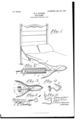
- FIG. 2 is a side elevation ot' the device.
- Fig. 3 is a fragmentary sectional view.
- Fig. 4 is an elevation, partly in section, of a fragment of a modified form of spring.
- Fig. 5 is a plan view of a securing or holding hook to be employed with wooden beds, and
- Fig. 6 is a view in perspective oi" an additional form of securing or holding means.
- l indicates a spiral spring made of one piece of wire.
- the wire is bent at one end to form the coiled hook 2, which is adapted to engage the flange or side strip of an iron bed or to engage the loop 3 oi' an eyebolt 4, threaded in the side of a wooden bed.
- the hook is so bent as to extend across the end of the spiralspring. rlhe coil of the l hook 21s at right angles to the direction of the coil of the spring 1.
- the opposite end portion 5 of the wire is bent at right angles and terminates in the hook 6, which is adapted to engage the pivotal -pin 7 of the clamp.
- the clamp consists of two sections 8 and 9, which have formed intermediate their lengths on both sides the ears 10, which overlap and receivethe pivotal pin 7.
- the outer portions of the. sections are slightly curved and have their ends normally contacting, between which in practice the bedclothes are to be inserted. extend outwardly to form the operating handles or levers 11.
- a spring 12 is provided.
- This spring consists of a strip of metal looped in its center, as at 18, to embrace the pin 7, and has its end portions 14 and 15 diverging and contacting with the handles or levers oi' the sections 11 at their under side.
- a central flexible connection 16 is employed between the opposite ends of the spring. One end of the connection is secured to the loop 2 and the opposite end within a recess or depression 17, vformed at the base of the straight portion 5.
- Fig. 4 illustrates a slightly-modified form of the invention.
- the device is or' the saine construction as before, with the exception that the end ot' the wire opposite the hooi; is bent at an angle and then coiled to form the eye a, thc said wire being then bent to form the tongue B.
- the return portion ot' the wire is then coiled to form an eye tremity of the wire is bent to lie approximately parallel with the angular portion c of the wire.
- the eyes are adapted to embrace the pivot of the clamp, and the end of the portion c bears against one of thcjaws of the clamp, while the tongue B, being resilient, bears against the opposite jaw.
- the free portion ot' the wire is also resilient and bears against the first-named jaw and tends to eX- ert a pressure ther-@against and hold the clamp in its normal or closed position.
- Fig. 5 illustrates a hook A which may be employed in place or' the eyebolt shown in Fig. 2.
- Fig. 6 shows a form of hook that may be employed when it is desired to secure the spring to a slat.
- the eye fr is engaged by the hook ot' the spring, and the an- 'lhe opposite portions of the sections to correspond withthe eye a, and the ex- ⁇ IIO gular hook portion ⁇ 1/ is adapted to engage a slat.
- the hooks illustrated may be made of wire or of [lat spring metal.
- extension at its opposite end, the extension beingbent upon itself to form a loop and then extended rearwardly and outwardly on an incline, then bent upon itself and extended around the loop and terminating in a rearwardly and outwardly extending' portions and a clamp consisting of two members pivoted one to the other, the loop of the straight portion of the spring encircling ⁇ the pivot of the members and the rearwardly and outwardly extending portions forming springs for holding the members in their closed or normal positions.
Landscapes
- Engineering & Computer Science (AREA)
- Mechanical Engineering (AREA)
- Clamps And Clips (AREA)
Description
10.798,529. -PATENTBD AUG.29,1905.
' w. D. PATRIGK. y
l BED CLAMP. APILIOATION FILED Dnc. 1904.
NETE@ STATES PATENT UFFCE.
BED-CLAMP..
Specification of Letters Patent.
Patented Aug. 29, 1905.
Application lei; December 8,1904. Serial No. 236,040.
To @ZZ 11171/0711/ t may concern,.-
Be it known that l, WILLIAM D. PATRICK, a citizen of the United States of America, residing` at Elba, in the county of Coffee and State of Alabama, have invented certain new and useful Improvements in BedCl-amps, of which the following is a specification.
This invention relates to bed-clamps, and more particularly to that class employing a spring. Y
It is an object of the invention to provide a device otl this class that can be readily applied to either a wooden or iron bed.
The invention has also for an object the provision of means whereby the movement of the spring is limited in one direction, and thereby greatly enhancing the effectiveness of the device.
Afurther object ot' the invention is to provide novel means, in combination with the spring, of holding the clamping-jaws closed or in their normal position.
It is also an object of the invention to produce a device of this character that will be simple in construction, eiiicient in practice, and economical to manufacture.
With the above and other objects in view the invention consists in the details oi' construction and in the arrangement and combination of parts to be hereinafter more fully described and claimed.
In describing the invention in detail reference will be had t0 the accompanying drawings, forming part of this specification, wherein like characters of reference will denote corresponding parts in the several views, and in which- Figurel is a view in perspective and partly in section of a fragment of a bed, showing the invention applied. Fig. 2 is a side elevation ot' the device. Fig. 3 is a fragmentary sectional view. Fig. 4 is an elevation, partly in section, of a fragment of a modified form of spring. Fig. 5 is a plan view of a securing or holding hook to be employed with wooden beds, and Fig. 6 is a view in perspective oi" an additional form of securing or holding means.
In the drawings, l indicates a spiral spring made of one piece of wire. The wire is bent at one end to form the coiled hook 2, which is adapted to engage the flange or side strip of an iron bed or to engage the loop 3 oi' an eyebolt 4, threaded in the side of a wooden bed. The hook is so bent as to extend across the end of the spiralspring. rlhe coil of the l hook 21s at right angles to the direction of the coil of the spring 1. The opposite end portion 5 of the wire is bent at right angles and terminates in the hook 6, which is adapted to engage the pivotal -pin 7 of the clamp. The clamp consists of two sections 8 and 9, which have formed intermediate their lengths on both sides the ears 10, which overlap and receivethe pivotal pin 7. The outer portions of the. sections are slightly curved and have their ends normally contacting, between which in practice the bedclothes are to be inserted. extend outwardly to form the operating handles or levers 11.
To hold the sections of the clamp in their normal or closed position, a spring 12 is provided. This spring consists of a strip of metal looped in its center, as at 18, to embrace the pin 7, and has its end portions 14 and 15 diverging and contacting with the handles or levers oi' the sections 11 at their under side.
To limit the movement or expansion of the spiral spring, a central flexible connection 16 is employed between the opposite ends of the spring. One end of the connection is secured to the loop 2 and the opposite end within a recess or depression 17, vformed at the base of the straight portion 5.
Fig. 4 illustrates a slightly-modified form of the invention.` In this form the device is or' the saine construction as before, with the exception that the end ot' the wire opposite the hooi; is bent at an angle and then coiled to form the eye a, thc said wire being then bent to form the tongue B. The return portion ot' the wire is then coiled to form an eye tremity of the wire is bent to lie approximately parallel with the angular portion c of the wire. The eyes are adapted to embrace the pivot of the clamp, and the end of the portion c bears against one of thcjaws of the clamp, while the tongue B, being resilient, bears against the opposite jaw. The free portion ot' the wire is also resilient and bears against the first-named jaw and tends to eX- ert a pressure ther-@against and hold the clamp in its normal or closed position.
Fig. 5 illustrates a hook A which may be employed in place or' the eyebolt shown in Fig. 2. v
Fig. 6 shows a form of hook that may be employed when it is desired to secure the spring to a slat. lIn this form the eye fr is engaged by the hook ot' the spring, and the an- 'lhe opposite portions of the sections to correspond withthe eye a, and the ex-` IIO gular hook portion `1/ is adapted to engage a slat.
The hooks illustrated may be made of wire or of [lat spring metal.
The construction and operation of the invention are thought to bc clearly apparent' from the Jforegoing description to those skilled in the art, it being noted that all changes may be resorted to that fairly fall within the scope of the claims hereunto annexed.
Having thus 'fully described my invention, what I claim as new, and desire to secure by Letters Patent, is-
l. In a device oic the character described, a coiled spring, securing means at one end, an extension on the opposite end and a clamp consisting' of two members pivoted one to the other, the extension ot' the spring engaging the pivot of the members and beingl bent to provide means for keeping the members of the clamp in normal contact.
2. In a device of the character described, a
coiled spring, securing means at one end, and
an extension at its opposite end, the extension beingbent upon itself to form a loop and then extended rearwardly and outwardly on an incline, then bent upon itself and extended around the loop and terminating in a rearwardly and outwardly extending' portions and a clamp consisting of two members pivoted one to the other, the loop of the straight portion of the spring encircling` the pivot of the members and the rearwardly and outwardly extending portions forming springs for holding the members in their closed or normal positions.
In testimony whereof I aflix my signature, in the presence of two witnesses, this 30th day of November, 1904.
VILLIAM D. PATRICK.
Witnesses:
B. DIXoN ARMSTRONG, M. J. LEE.
Priority Applications (1)
| Application Number | Priority Date | Filing Date | Title |
|---|---|---|---|
| US23604004A US798529A (en) | 1904-12-08 | 1904-12-08 | Bed-clamp. |
Applications Claiming Priority (1)
| Application Number | Priority Date | Filing Date | Title |
|---|---|---|---|
| US23604004A US798529A (en) | 1904-12-08 | 1904-12-08 | Bed-clamp. |
Publications (1)
| Publication Number | Publication Date |
|---|---|
| US798529A true US798529A (en) | 1905-08-29 |
Family
ID=2867017
Family Applications (1)
| Application Number | Title | Priority Date | Filing Date |
|---|---|---|---|
| US23604004A Expired - Lifetime US798529A (en) | 1904-12-08 | 1904-12-08 | Bed-clamp. |
Country Status (1)
| Country | Link |
|---|---|
| US (1) | US798529A (en) |
Cited By (2)
| Publication number | Priority date | Publication date | Assignee | Title |
|---|---|---|---|---|
| US2616143A (en) * | 1951-11-30 | 1952-11-04 | Ford R Falkner | Broom hanger |
| US5622297A (en) * | 1995-07-28 | 1997-04-22 | Safariland Ltd., Inc. | Adjustable handgun holster |
-
1904
- 1904-12-08 US US23604004A patent/US798529A/en not_active Expired - Lifetime
Cited By (2)
| Publication number | Priority date | Publication date | Assignee | Title |
|---|---|---|---|---|
| US2616143A (en) * | 1951-11-30 | 1952-11-04 | Ford R Falkner | Broom hanger |
| US5622297A (en) * | 1995-07-28 | 1997-04-22 | Safariland Ltd., Inc. | Adjustable handgun holster |
Similar Documents
| Publication | Publication Date | Title |
|---|---|---|
| US798529A (en) | Bed-clamp. | |
| US565255A (en) | Hair-pin | |
| US1182822A (en) | Fishing-sinker. | |
| US1093945A (en) | Hook. | |
| US879232A (en) | Bale-tie fastener. | |
| US978519A (en) | Sinker. | |
| US542827A (en) | Fence-building tool | |
| US1141145A (en) | Clip. | |
| US318092A (en) | Bed-spring | |
| US1068837A (en) | Fastening-clip. | |
| US757420A (en) | Wire clip for cushion-spring work. | |
| US562907A (en) | Hook for toe-pads | |
| US837247A (en) | Line-fastener. | |
| US207833A (en) | Improvement in springs for bed-bottoms | |
| US1147616A (en) | Bedclothes-fastener. | |
| US591429A (en) | Snap-hook | |
| US139077A (en) | Improvement in wire mattresses | |
| US837923A (en) | Bed-bottom. | |
| US872852A (en) | Napkin-holder. | |
| US861829A (en) | Trace-clip. | |
| US951929A (en) | Wagon-box fastener. | |
| US1098466A (en) | Lantern-rack. | |
| US488230A (en) | Tension device | |
| US331637A (en) | Clabence james hamilton | |
| US1136244A (en) | Clothes-clamp. |