US8024135B2 - Ultraviolet lidar for detection of biological warfare agents - Google Patents
Ultraviolet lidar for detection of biological warfare agents Download PDFInfo
- Publication number
- US8024135B2 US8024135B2 US11/104,505 US10450505A US8024135B2 US 8024135 B2 US8024135 B2 US 8024135B2 US 10450505 A US10450505 A US 10450505A US 8024135 B2 US8024135 B2 US 8024135B2
- Authority
- US
- United States
- Prior art keywords
- signals
- fluorescence
- pseudo
- backscattered
- airborne agents
- Prior art date
- Legal status (The legal status is an assumption and is not a legal conclusion. Google has not performed a legal analysis and makes no representation as to the accuracy of the status listed.)
- Expired - Fee Related, expires
Links
Images



Classifications
-
- G—PHYSICS
- G01—MEASURING; TESTING
- G01N—INVESTIGATING OR ANALYSING MATERIALS BY DETERMINING THEIR CHEMICAL OR PHYSICAL PROPERTIES
- G01N21/00—Investigating or analysing materials by the use of optical means, i.e. using sub-millimetre waves, infrared, visible or ultraviolet light
- G01N21/62—Systems in which the material investigated is excited whereby it emits light or causes a change in wavelength of the incident light
- G01N21/63—Systems in which the material investigated is excited whereby it emits light or causes a change in wavelength of the incident light optically excited
- G01N21/64—Fluorescence; Phosphorescence
- G01N21/645—Specially adapted constructive features of fluorimeters
- G01N21/6456—Spatial resolved fluorescence measurements; Imaging
-
- G—PHYSICS
- G01—MEASURING; TESTING
- G01N—INVESTIGATING OR ANALYSING MATERIALS BY DETERMINING THEIR CHEMICAL OR PHYSICAL PROPERTIES
- G01N21/00—Investigating or analysing materials by the use of optical means, i.e. using sub-millimetre waves, infrared, visible or ultraviolet light
- G01N21/17—Systems in which incident light is modified in accordance with the properties of the material investigated
- G01N21/25—Colour; Spectral properties, i.e. comparison of effect of material on the light at two or more different wavelengths or wavelength bands
- G01N21/31—Investigating relative effect of material at wavelengths characteristic of specific elements or molecules, e.g. atomic absorption spectrometry
- G01N21/35—Investigating relative effect of material at wavelengths characteristic of specific elements or molecules, e.g. atomic absorption spectrometry using infrared light
- G01N21/3504—Investigating relative effect of material at wavelengths characteristic of specific elements or molecules, e.g. atomic absorption spectrometry using infrared light for analysing gases, e.g. multi-gas analysis
-
- G—PHYSICS
- G01—MEASURING; TESTING
- G01N—INVESTIGATING OR ANALYSING MATERIALS BY DETERMINING THEIR CHEMICAL OR PHYSICAL PROPERTIES
- G01N21/00—Investigating or analysing materials by the use of optical means, i.e. using sub-millimetre waves, infrared, visible or ultraviolet light
- G01N21/17—Systems in which incident light is modified in accordance with the properties of the material investigated
- G01N21/47—Scattering, i.e. diffuse reflection
-
- G—PHYSICS
- G01—MEASURING; TESTING
- G01N—INVESTIGATING OR ANALYSING MATERIALS BY DETERMINING THEIR CHEMICAL OR PHYSICAL PROPERTIES
- G01N21/00—Investigating or analysing materials by the use of optical means, i.e. using sub-millimetre waves, infrared, visible or ultraviolet light
- G01N21/62—Systems in which the material investigated is excited whereby it emits light or causes a change in wavelength of the incident light
- G01N21/63—Systems in which the material investigated is excited whereby it emits light or causes a change in wavelength of the incident light optically excited
- G01N21/64—Fluorescence; Phosphorescence
- G01N21/6408—Fluorescence; Phosphorescence with measurement of decay time, time resolved fluorescence
-
- G—PHYSICS
- G01—MEASURING; TESTING
- G01N—INVESTIGATING OR ANALYSING MATERIALS BY DETERMINING THEIR CHEMICAL OR PHYSICAL PROPERTIES
- G01N21/00—Investigating or analysing materials by the use of optical means, i.e. using sub-millimetre waves, infrared, visible or ultraviolet light
- G01N21/62—Systems in which the material investigated is excited whereby it emits light or causes a change in wavelength of the incident light
- G01N21/63—Systems in which the material investigated is excited whereby it emits light or causes a change in wavelength of the incident light optically excited
- G01N21/64—Fluorescence; Phosphorescence
- G01N21/645—Specially adapted constructive features of fluorimeters
-
- G—PHYSICS
- G01—MEASURING; TESTING
- G01N—INVESTIGATING OR ANALYSING MATERIALS BY DETERMINING THEIR CHEMICAL OR PHYSICAL PROPERTIES
- G01N21/00—Investigating or analysing materials by the use of optical means, i.e. using sub-millimetre waves, infrared, visible or ultraviolet light
- G01N21/17—Systems in which incident light is modified in accordance with the properties of the material investigated
- G01N2021/1793—Remote sensing
-
- G—PHYSICS
- G01—MEASURING; TESTING
- G01N—INVESTIGATING OR ANALYSING MATERIALS BY DETERMINING THEIR CHEMICAL OR PHYSICAL PROPERTIES
- G01N21/00—Investigating or analysing materials by the use of optical means, i.e. using sub-millimetre waves, infrared, visible or ultraviolet light
- G01N21/17—Systems in which incident light is modified in accordance with the properties of the material investigated
- G01N21/25—Colour; Spectral properties, i.e. comparison of effect of material on the light at two or more different wavelengths or wavelength bands
- G01N21/31—Investigating relative effect of material at wavelengths characteristic of specific elements or molecules, e.g. atomic absorption spectrometry
- G01N21/35—Investigating relative effect of material at wavelengths characteristic of specific elements or molecules, e.g. atomic absorption spectrometry using infrared light
- G01N21/3504—Investigating relative effect of material at wavelengths characteristic of specific elements or molecules, e.g. atomic absorption spectrometry using infrared light for analysing gases, e.g. multi-gas analysis
- G01N2021/3513—Open path with an instrumental source
-
- G—PHYSICS
- G01—MEASURING; TESTING
- G01N—INVESTIGATING OR ANALYSING MATERIALS BY DETERMINING THEIR CHEMICAL OR PHYSICAL PROPERTIES
- G01N21/00—Investigating or analysing materials by the use of optical means, i.e. using sub-millimetre waves, infrared, visible or ultraviolet light
- G01N21/17—Systems in which incident light is modified in accordance with the properties of the material investigated
- G01N21/47—Scattering, i.e. diffuse reflection
- G01N2021/4704—Angular selective
- G01N2021/4709—Backscatter
-
- G—PHYSICS
- G01—MEASURING; TESTING
- G01N—INVESTIGATING OR ANALYSING MATERIALS BY DETERMINING THEIR CHEMICAL OR PHYSICAL PROPERTIES
- G01N21/00—Investigating or analysing materials by the use of optical means, i.e. using sub-millimetre waves, infrared, visible or ultraviolet light
- G01N21/62—Systems in which the material investigated is excited whereby it emits light or causes a change in wavelength of the incident light
- G01N21/63—Systems in which the material investigated is excited whereby it emits light or causes a change in wavelength of the incident light optically excited
- G01N21/64—Fluorescence; Phosphorescence
- G01N21/645—Specially adapted constructive features of fluorimeters
- G01N2021/6463—Optics
-
- G—PHYSICS
- G01—MEASURING; TESTING
- G01N—INVESTIGATING OR ANALYSING MATERIALS BY DETERMINING THEIR CHEMICAL OR PHYSICAL PROPERTIES
- G01N21/00—Investigating or analysing materials by the use of optical means, i.e. using sub-millimetre waves, infrared, visible or ultraviolet light
- G01N21/62—Systems in which the material investigated is excited whereby it emits light or causes a change in wavelength of the incident light
- G01N21/63—Systems in which the material investigated is excited whereby it emits light or causes a change in wavelength of the incident light optically excited
- G01N21/64—Fluorescence; Phosphorescence
- G01N2021/6495—Miscellaneous methods
Definitions
- This invention relates in general to laser induced detecting and ranging (LIDAR) systems.
- BWA bio-warfare agent sensing
- point detectors where a local sample is taken—either in the form of air sampler or a swab—and analyzed.
- the analysis can be based on immuno-assay, culture, or even a fluorescence based aerosol particle sizer or detector.
- a stand-off detector does not need to bring the sample to it for analysis, and is thus able to provide advance warning even before the BW agent arrives near the sensor, and operates continuously—not batch processing.
- Stand-off sensors for the detection and discrimination of bio-warfare agent aerosols have been used for performing the task of round-the-clock surveillance to provide advance warning for personnel of the release of a BWA.
- a fluorescence lidar which first detects aerosol particles by elastic light scattering and then employs UV laser excitation to generate auto-fluorescence from the proteins contained in the BWA particles for discrimination, is well established as a technique of choice for the stand-off BWA sensor.
- fluorescence sensors are not capable of specific identification, their real-time capability for standoff and point detection and discrimination with low false alarm rates makes them well suited as the first sensor in a suite of sensors.
- UV fluorescence lidars have conventionally required a large, high energy UV laser source and are consequently bulky, and expensive, which in turn have limited the utility of standoff lidar sensors. Indeed, in view of the small fluorescence cross sections for most of the BW agents, fluorescence lidars have relied upon high peak power (multi kW) pulsed solid state UV lasers to generate sufficient fluorescence signal from BW agent aerosols to achieve adequate measurement range and sensitivity.
- UV laser sources have limited the application of UV laser sources in lidar sensor applications.
- One object of at least one embodiment of the present invention is to provide a system and method for lidar detection which can utilize the recent availability of semiconductor ultraviolet optical source (SUVOS) semiconductor UV laser diodes.
- SUVOS semiconductor ultraviolet optical source
- Another object of an embodiment of the present invention is to provide a compact stand-off BW sensor that can be widely deployed.
- Another object of an embodiment of the present invention is to provide miniature sensor systems which can be mounted on robotic air-borne and ground vehicles thereby enhancing the BWA detection capability.
- the system includes a semiconductor ultraviolet optical source configured to emit an ultraviolet light, a controller configured to generate a pseudo-random code for emission of the ultraviolet light modulated at the pseudo-random code, a telescope configured to focus the ultraviolet light to a distance from the source and to receive elastically backscattered signals and fluorescence signals from the distance, and a sensor configured to detect the elastically backscattered and fluorescence signals.
- the method according to one embodiment of the present invention generates a pseudo-random code and emits at least one wavelength of ultraviolet light modulated at the pseudo-random code, transmits the modulated ultraviolet light pulses to a distance from the source, receives elastically backscattered signals and fluorescence signals from the distance, and detects the elastically backscattered and fluorescence signals.
- FIG. 1 is an optical and electronic system layout of a UV biological trigger lidar breadboard sensor of a preferred embodiment of the present invention
- FIG. 2 depicts lidar profiles, i.e., aerosol backscatter signal vs. range profiles, obtained with a preferred embodiment of the present invention by cross correlating the received signal with a pseudo-random modulation code applied to the broadcast signals;
- FIG. 3 is a photograph of a portable semiconductor UV laser diode based aerosol and fluorescence lidar breadboard of a preferred embodiment of the present invention
- FIG. 4 depicts a signal in the three receiver channels vs. BG ( bacillus globigii ) particle concentration, as measured against an aerodynamic particle sizer (APS);
- BG bacillus globigii
- FIG. 5 depicts a signal in the three receiver channels vs. OV (ovalbumin) concentration, as measured against APS;
- FIG. 6 is a one-dimensional time series color image of aerosol cloud evolution for BG stimulant release
- FIG. 7 is a false color time series depiction of lidar range profile data shown for yellow smoke grenade (interferent) release;
- FIG. 8 is a two-dimensional (R- ⁇ ) false color aerosol cloud images for the time series depicted in FIG. 7 ;
- FIG. 10 depicts a two parameter plot of several BWA stimulants and interferents detected by the lidar system according to a preferred embodiment of the present invention
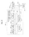
- FIG. 11 illustrates one embodiment of a computer system utilized by a lidar system of the present invention that may be implemented.
- FIG. 12 depicts a flowchart illustrating one preferred method of the present invention.
- a direct replacement of the pulsed solid state UV laser by the low power UV laser diodes would drastically reduce the range capability and sensitivity of such a lidar.
- semiconductor UV laser diodes are low power continuous-wave (cw) or pulsed devices with output powers of the order of tens of mW.
- PRM pseudo random modulation
- adequate sensitivity and range performance for the lidar system of the present invention are expected even at 10 mW power level of UV laser diodes. Accordingly, the present invention can realize a practical semiconductor ultraviolet optical source (SUVOS) for a BWA stand-off sensor.
- SUVS semiconductor ultraviolet optical source
- a short laser pulse is transmitted into the atmosphere, and a range resolved lidar profile is generated by time gating the signal backscattered by the aerosol and molecular components present in the beam path.
- a cw laser is utilized, and its output is amplitude modulated by a continuously repeating PR code (e.g., the A code or the M code) of a fixed length.
- the pseudo-random code can be based on a cyclic, digital (1 or 0) Nth order PR code.
- the M-code refers to maximum-length pseudo-random digital sequence (i.e., a sequence composed of ones and zeros) and usually generated by shift register by known procedures.
- a codes were introduced to avoid a common problem with the M-code, where the number of ones always exceeds the number of zeros by one, and thus includes the background noise in the correlation. See Y. Emery and C. Flesia, “Use of A1 and A2 sequences to modulate continuous-wave pseudorandom noise lidar”, Applied Optics, 37, 12, 2238-2242, 1998, the entire contents of which are incorporated herein by reference.
- one property of a PR modulated signal is that its autocorrelation yields an approximate delta function profile.
- This property permits a range resolved lidar profile to be constructed by correlating the lidar signal with the PR code, with the correlation time delay corresponding to the round trip time to the object and the correlation amplitude corresponding to the lidar signal strength.
- PRM technology as applied in the present invention is thus uniquely suited for the BW agent stand-off sensor, owing to PRM to utilize a cw light source for range resolved measurements. Further, PRM has a high sensitivity, due to the phase sensitive detection characteristics thereof.
- the average output power can be comparable to a semiconductor laser diode.
- a micro-chip laser with a 1 ⁇ J/pulse, 1 ns pulse duration and 10 kHz pulse repetition frequency corresponds to 1 kW peak power, but the average power is 10 mW. Since the PRM lidar technique of the present invention permits continuous measurement, it in effect allows a low average power source to function as effectively as a high peak power pulsed laser.
- the ultraviolet lidar sensor of the present invention employs a low-power ( ⁇ 5 mW), continuous-wave, 375 nm semiconductor laser diode that was modulated at high-speed with a pseudo-random (PR) code to provide range-resolved lidar detection of both aerosol elastic scattering and fluorescence.
- the sensor incorporates a 150 mm diameter receiver telescope and 3 photon-counting detection channels centered at 375 nm, 440 nm, and 550 nm. Aerosol elastic and fluorescence lidar profiles were obtained by correlating the signal photon-counts with the PR code.
- Demonstrations of the present invention have detected stimulants at a lidar range of 7.5 m, and in one embodiment of the present invention stimulants have been detected at a lidar range of several hundred meters, using a continuously scanned ( ⁇ 13°) LIDAR in a horizontal plane to detect downwind stimulant and interferent aerosol disseminations.
- FIG. 1 shows an optical and electronic system layout of one PRM lidar breadboard according to a preferred embodiment of the present invention, hereinafter referred to as UBTL (Ultraviolet Biological Trigger Lidar), because of its application as a front-end trigger sensor for other point sensors.
- UBTL Ultraviolet Biological Trigger Lidar
- a 375 nm laser diode supplied by CREETM constituted the active optical source component of the lidar system of the present invention.
- the 375 nm laser diode was packaged on a standard TO-9 semiconductor diode header without a cover or window.
- the peak power output of the 375 nm laser diodes was about 10 mW.
- a compact thermoelectrically cooled mount maintained the temperature of the laser constant throughout the experiments.
- the laser diode mount was also furnished with a fused silica aspheric lens for collimating the output.
- a high speed laser diode current driver was used to supply the current and also to modulate its output.
- the output power of the diode was found to decrease gradually due to aging.
- the threshold voltage of the diode also correspondingly increased.
- a laser control circuit of the present invention is configured to maintain the laser power output nearly constant, by monitoring the laser output power by a photodiode and increasing the driver output voltage.
- a pseudo-random generator can be a deterministic algorithm that generates a sequence of numbers with little or no discernible pattern in the numbers, except for broad statistical patterns. Deterministic algorithms are known in the art.
- a PR code generator e.g., an FPGA Field Programmable Gate Array on for example a programmable logic (TTL) IC chip
- TTL programmable logic
- FIG. 2 depicts lidar profiles, i.e., aerosol backscatter signal vs. range profiles, obtained in the present invention by cross correlating the received signal with a pseudo-random modulation code applied to the broadcast signals.
- a two mirror optical scheme was employed for the laser beam transmitter in a preferred embodiment of the present invention.
- This arrangement allowed boresighting of the lidar, which was done by adjusting the overlap between the transmitted beam and the telescope field of view (FOV).
- the range where full overlap of the transmitted beam with the receiver FOV occurred could be varied from about 5 m to 50 m or longer by changing the angle of the transmitted beam.
- a 150 mm diameter aperture commercial Maksutov-Cassegrain telescope served as the receiver. This telescope was chosen mainly because of its good image quality, good transmittance in the UV and visible wavelengths, and ready availability at a reasonable low cost, despite its size and weight.
- the telescope in one embodiment of the present invention collects signals from a far field, i.e., from a source remote from the telescope such that signals arriving at the telescope arrive along optical rays nearly parallel (as from a source at infinity).
- Signals collected by the telescope were divided into three spectral channels by dichroic beam dividers (BD 1 . . . . BD 3 )—one in UV for detecting the elastic scattered light and two in the visible (blue and green channels) for detecting the fluorescence. Since the lidar system of the present invention can be expected to operate at night, all three channels can be equipped with wide bandpass filters (F 1 . . . F 3 ).
- FIG. 1 shows schematically the optical system including lenses for imaging the telescope aperture on the detectors.
- Optical ray trace analysis was utilized to set the optical configuration, as shown in FIG. 1 , to arrange the three detector channels so as to receive signals from signals the same spatial region.
- the optical ray trace analysis provided an estimate of the overlap function as a function of range for the lidar for any given alignment of the transmitter beam with respect to the FOV of the telescope.
- Optical signal detection in the present invention can be done in all the three receiver channels with for example photon counting channel photomultiplier tube modules.
- the detector outputs from these modules includes TTL pulses corresponding to the photon counts.
- a multi-channel scaler (MCS) can be used to time resolve and store the data.
- Excellent time resolution (400 ps) can be achieved by employing a PC based high speed time of flight card.
- This card may also have multi channel scaling ability.
- two such boards can be used with the UV elastic channel detector attached to one time of flight card, whereas the blue and green fluorescence channel detector outputs were multiplexed, so that they could share the second time of flight card. Multiple cards can be used.
- the PR coded light from the laser diode was continuously transmitted with continuous code repetitions.
- data acquisition was synchronized with the PR code, and the data from every subsequent code length was accumulated with those from earlier codes.
- each code took 2.54 ⁇ s to generate and about 3 ⁇ 10 5 data acquisitions/sec were possible, after taking into account the short set up times of the MCS board for every data acquisition.
- FIG. 3 shows a photograph of the lidar sensor breadboard.
- the rectangular enclosure attached to the top of the telescope contains the laser diode transmitter, PRM code generator, laser diode driver, receiver optics train and detectors.
- a transportable half-height instrument rack (see photograph) contains a rack mount PC used for lidar operation, data acquisition and display. The two time of flight/MCS data acquisition cards were inside the LIDAR computer. Also seen in the top shelf of the rack are the computer display monitor screen and the keyboard. The next component seen in the rack is a box containing dc power supplies for the transceiver head. The component at the bottom of the rack is the UPS power supply.
- the lidar transceiver head can be mounted on a motorized rotary platform, which in turn is attached to a tripod that provided pan, tilt, and height adjustments for the lidar.
- the instrument can be leveled such that it scans in a horizontal plane.
- the rotary table can be programmed to constantly scan over a ⁇ 13° arc, taking approximately 2 minutes for each forward or backward scan.
- a software suite assists in lidar operation and data analysis.
- deriving the target response i.e., lidar aerosol and fluorescence profiles
- deriving the target response includes calculating the cross correlation of the averaged PRM signal with the PR code, such calculations being performed in the LIDAR computer or other computer processor.
- the cross correlation in one embodiment of the present invention can be performed in software.
- hardware devices can likewise perform the cross correlations. Indeed, correlations involve several computational steps and formerly took very long times before high speed computers were available. Many instruments used hardware correlators which were very expensive. But, use of an efficient mathematical procedure to rapidly complete correlation calculations and the use of a high speed computer permit correlation results to be available in near real-time.
- a computer program combined with the data analysis algorithm directly provides the target response.
- the computer program allows real-time operation of lidar by 1) running the lidar system, 2) carrying out data acquisition, 3) doing correlations and 4) displaying the correlation function—which is the target response, or in this case the aerosol cloud and any other hard targets in lidar FOV.
- Lidar operation in one embodiment of the present invention sends a series of PRM coded pulses and acquisition of data from the elastic and one of the fluorescence channels for about 6 secs, transfers the MCS outputs to hard disk for storage, and then initiates the next measurement from the elastic and the second fluorescence channel for 6 secs.
- Each 6 sec measurement corresponded to averaging over an approximately 2° arc, controlled in one embodiment by the above noted computer program.
- a lidar system according to one embodiment of the present invention was tested with BW stimulant aerosols in a 70 m 3 testing chamber equipped with aerosol dispersal equipment, observation ports, mixing fans, evacuation pumps and HEPA filters. Although the chamber was furnished with optical windows, two windowless shuttered ports were used, the shutter ports being opened for brief periods during the experiments thus avoiding strong elastic scatter and spurious fluorescence from the windows. Such an approach introduced a new constraint in the form of a short observation period ( ⁇ 10 sec), and introduced minor uncertainties in the reported concentrations caused by the opening and closing of ports.
- the lidar system according to one embodiment of the present invention was mounted for this test outside the testing chamber on a tripod at a height of 1.5 m above the floor and pointed horizontally through the 200 mm diam. observation port on the chamber wall.
- the testing chamber had a second, identical port in line with the first on the opposite chamber wall.
- the lidar sensor head was aligned during this test so that both the laser beam and the telescope field-of-view passed through the two ports when the inner and outer metal shutters were opened.
- the lidar sensor head of the present invention was located 5 m from the entrance port, and a beam-stop including a vertically mounted, low-pile black velvet cloth was located 1.5 m beyond the exit port. Aerosol testing path length in the chamber was ⁇ 5 m between the entrance and exit ports.
- a calibrated APS (aerodynamic particle sizer instrument) was located in the center of the chamber below the beam path to provide a continuous record of the estimate of aerosol particle size distributions.
- the APS data system computed averaged particle size distribution
- a 375 nm CREETM laser diode with about a 2.6 mW transmitted output power was used. Co-boresight alignment between the laser transmitter and the receiver telescope field-of-view was adjusted for maximum elastic backscatter from the chamber atmosphere.
- the maximum elastic backscatter in the UBTL lidar was achieved when the laser beam was aligned to cross through the telescope FOV in the chamber and the FOV was increased to its maximum value of 8 mrad.
- cps counts/sec
- the UBTL instrument of the present invention was tested with varying amounts of aerosol loadings of stimulants—BG ( bacillus globigii ), OV (ovalbumin) and Kaolin, and obtained strong blue and green fluorescence signals of several thousand cps, as well as strong elastic backscatter signals. Saturation of the 375 nm UV detection channel was prevented by a neutral density filter with optical density 2 (OD 2), to provide 100:1 attenuation.
- BG bacillus globigii
- OV ovalbumin
- Kaolin a neutral density filter with optical density 2
- Lidar data counts were ⁇ 9 ⁇ 10 6 photo-electron counts/sec in UV channel after correcting for the attenuator, 1 ⁇ 10 4 and 3 ⁇ 10 3 counts/sec in the blue and green fluorescence channels respectively.
- the aerosol particle concentration in the chamber was lowered in successive increments by approximately a factor of two for each step. For the first six or seven reductions in concentration, both the UV-elastic and fluorescence detector counts decreased approximately by the same factor (see FIG. 4 ).
- the particle concentration was reduced below 2.5 ⁇ 10 4 ppl, the aerosol fluorescence signal merged into the interfering background signals due to the chamber beam walls and the beam stop. With OV dissemination, the starting concentration was ⁇ 4 ⁇ 10 5 ppl, (about a third of BG).
- Photo-electron counts of ⁇ 6.5 ⁇ 10 6 counts/sec in UV channel, 9 ⁇ 10 3 and 10 ⁇ 10 3 counts/sec in the blue and green fluorescence channels respectively were obtained (see FIG. 5 ), which are only slightly smaller than those for BG. This was expected because of the higher cross sections for OV when compared to those for BG. With Kaolin the starting concentration was 1.1 ⁇ 10 6 ppl, the counts were ⁇ 2.4 ⁇ 10 7 counts/sec in UV channel, 2 ⁇ 10 3 and 1 ⁇ 10 3 counts/sec in the blue and green fluorescence channels respectively were obtained.
- Kaolin is non-fluorescent, finite signals in both fluorescence channels were obtained—indicating that there was either a leak of elastically scattered photons into the fluorescence channels, or the possibility of impurities in the sample of Kaolin or the contamination of Kaolin with the fluorescent materials in the disseminator.
- a lidar system according to one embodiment of the present invention was tested under ambient, field conditions including at nighttime in a 2-km field test grid.
- Field tests involved dissemination of various bio-warfare stimulants such as BG, EH, and MS2, and interferents during multiple test windows on separate nights.
- bio-warfare stimulants such as BG, EH, and MS2, and interferents during multiple test windows on separate nights.
- Various dissemination methods including ground point and line sources, ground-based vehicle, and aircraft were used.
- the field tests included nighttime blind disseminations of stimulant, or interferent aerosols for short durations (10 to 20 min) during specific time windows. These downwind disseminations were released at an unknown distance upstream from the instruments so that the wind carried the aerosol clouds over the sensors. Since the wind pattern and the spread of the aerosol could not be determined prior to the test, the UBTL sensor in the lidar system of the present invention was continuously scanned in the horizontal plane for these tests. For these tests, the horizontal scan pattern was set to a nominal 26° full-angle scan at 0.2°/sec angular speed with a continuous back and forth motion, in order to extend the spatial coverage of the UBTL lidar measurements to a wedge-shaped sector region. However, no elevation scans were done during these experiments.
- the UBTL instrument assembly of the present invention for these tests was mounted in the back of a truck with the lidar FOV pointing within 1° of horizontal, at a height of 2 m above the local ground level.
- the UBTL FOV was unrestricted except for a hard-target presented by a 2 m high mini-trailer at ⁇ 130 m range.
- the body of the trailer blocked the beam for approximately a 2° sector (where the lidar signals were saturated), and served as a pointing reference to calibrate the scan angle.
- the scanner did not have an encoder, and only relative scan angle command information was available.
- the lidar software described above included programming steps to produce lidar-waveform displays, to provide backscattered elastic and fluorescence signatures as a function of range, and to tabulate the total counts per sec under the correlation lidar curve as well as the total counts under the backscatter peak (integrated down to 5% of the peak value).
- Data obtained includes a series of detector counts S(N), the number N is the number of time intervals to accommodate one code length on the MCS data system.
- the data obtained being equal to the time for one full code length ⁇ sampling rate (e.g., 2.54 microsec ⁇ 2000 samples/microsec) as in the UBTL of the present invention with 100 MHz clock, 254 bit code, 500 ps MCS data system.
- the step size is of course the time step (here 500 ps) with which the signal return is collected.
- the total time for one code length corresponds to the longest unambiguous range that can be used—here it is 2.54 ⁇ s or 190.5 m range (round trip distance is 381 m).
- lidar profiles i.e., aerosol strength and fluorescence strength
- This data is also plotted as false color plots in 1- or 2-D displays.
- This analysis procedure constructs a false color strip chart display by arranging each of the successive lidar backscatter or fluorescence signal versus range (R) profiles (i.e., correlation function counts rendered in false color vs. range) in a time series plot.
- FIG. 6 shows the UV elastic channel false color time series lidar signal vs. range plots for BG dissemination.
- the x-coordinate is time, which increases monotonously from left to right. The data thus corresponds to scans first in clockwise direction and then in the counterclockwise direction approximately every two minutes.
- dark blue color denotes the baseline signal (or low signal), with the lighter blues, yellows and reds denoting successively higher signal strength.
- FIG. 4 shows the radial plots of the same UV elastic channel data for 4 scans covering the time period 21:46 to 21:55 hrs.
- Each of the radial plots represents a 2-dimensional snapshot of the aerosol cloud, and successive plots show the evolution of the aerosol cloud.
- FIG. 7 shows the false color time series lidar signal vs. range plots for all three channels, i.e., UV elastic, blue and green fluorescence for yellow smoke (interferent) dissemination. Data from each of the three spectral channels are shown in separate data windows. The vertical stripes in the UV elastic channel (top window) correspond to the trailer blocking the lidar FOV. Here also, blue color denotes the baseline (or low signal), with the yellows and reds denoting higher signal strength.
- FIG. 8 shows the radial plots of the same data in the three spectral channels for 4 scans covering the time period 22:49 to 22:56 hrs.
- FIG. 9 shows the false color time series and the radial plots for another test window, where a stimulant MS2 was disseminated.
- UV elastic channel data indicates start of disseminant release at ⁇ 21:12 and continuing up to 21:32, with a break in the middle. Strong fluorescence is seen in the blue fluorescence channel but not in the green channel.
- the UBTL sensor of the lidar system of the present invention using a 375 nm SUVOS laser diode with 5 mW transmitted power has demonstrated stand-off measurements of BW agent stimulant aerosols and interferents with a few hundred meter range.
- the UBTL sensor of the present invention has demonstrated that fluorescence measurements at up to 100 m range.
- the instrument sensitivity for BG fluorescence was roughly estimated to be ⁇ 10 Kppl, whereas aerosol elastic scatter detection levels were ⁇ 1 Kppl. This estimate is based on the lidar response measured during the ECBC test with BG. By optimization of the optics and by increasing the laser power we expect to reach fluorescence detection sensitivity levels approaching 1 Kppl.
- the present invention can be further complemented with an algorithm for the real time discrimination of BW aerosols from other types of aerosols and complemented with additional excitation and detector channels.
- One function of the bio-lidar is to effectively discriminate between BWA clouds and other non-hazardous clouds or interferents, so as to achieve reasonable false alarms incidence rates of ⁇ 1 in every 24 hours.
- aerosol cloud detection relies on information from the elastic channel
- discrimination requires the signals from Fluorescence channels.
- these three signal returns define an aerosol cloud signature to compare against a database to classify the type of cloud.
- the lidar system of the present invention cannot identify the exact material make-up of an aerosol cloud, it is able to discriminate between Agents of Biological Origin (ABO) and obscurants, naturally occurring pollens, and petrochemical fumes.
- ABO Agents of Biological Origin
- the optical fluorescence sensors in the present invention are suitable as both trigger and detect-to-warn devices because of their rapid response and negligible operating costs.
- Auto-fluorescence is generated when the BWA particles are excited with UV or visible radiation.
- the main fluoro-phores are: 1) Aromatic amino acids tryptophan, tyrosine, and phenylalanine: excitation—240-280 nm and fluorescence—280-350 nm; 2) NADH and NADPH: excitation peak—340 nm and fluorescence peak—450 nm; and 3) Flavin compounds: excitation peak—450 nm and fluorescence 515-565 nm.
- Discrimination between biological and non-biological particles can for example be achieved in the present invention by comparing the fluorescence intensities at these wavelengths.
- the size and shape morphology of BW agent particles can also used in addition in some of these sensors to improve the discrimination. This requires measurement of elastic scatter in addition to fluorescence.
- the BWA sensor of the lidar system of the present invention can effectively discriminate between the fluorescence from BWA particles and other naturally occurring non-bio (dust, smoke and soot, etc) and bio-particles (such as, pollen, human and animal cells, other background bacteria and fungal spores), and interferents, with very low probability for false alarms P fa .
- bio-particles such as, pollen, human and animal cells, other background bacteria and fungal spores
- interferents with very low probability for false alarms P fa .
- Several measurable parameters have been considered for discrimination, and include fluorescence intensities in one or more spectral bands corresponding for example to tryptophan (340 nm), NADH (440 nm) or Flavin (540 nm), and elastic scattering in one or two wavelengths for inferring the size of particles.
- the lidar system of the present invention performs an analysis of the aerosol cloud that can accurately discriminate between ABO's and non-threatening aerosols in ten seconds.
- Fluorescence aerosol particle sensors of the present invention utilize a procedure similar to that demonstrated by the BAWS sensors as described by Jeys, 1998, Primmerman, 2000, the entire contents of which are herein incorporated by reference, where the relative fluorescence efficiencies are calculated in the two spectral regions and normalized to the elastic signal.
- the detection/analysis technique of the present invention includes in one embodiment an additional elastic scatter channel in the IR (e.g., 1 ⁇ m).
- the stand-off lidar sensor can determine X, a particle size parameter.
- the stand-off lidar determines Y, a particle fluorescence efficiency parameter.
- FIG. 10 shows the two parameter plot of several BWA stimulants and interferents tested by the stand-off lidar according to one embodiment of the present invention.
- the computer algorithm has the ability to quickly process data and discriminate on objects of interest.
- each channel has a consistent background level. This background must be appropriately subtracted in order to determine the signal returning from objects of interest. The process for determining and subtracting these background levels were described in detail in the previous section.
- the signals After the signal for the object of interest is found in each channel, the signals must be properly correlated and compared. It is possible that the signals in the three channels may be displaced in range by one or more range bins. Depending on the nature of the object of interest, some wavelengths might penetrate deeper into the cloud than others. Hence, the signals are correlated in range first so that the signals will all be measured at the same distance. Secondly, the size of the cloud is set by the smallest elastic signal. That is, if the UV channel determines that the cloud is 45 m deep and the IR sees 63 m into the cloud, only the first 45 m of the cloud are analyzed. The signal from each channel is then defined as the total signal in the range of interest.
- the signature as defined previously has a range dependence due to atmospheric effects and system optical parameters.
- the range dependence is mathematically determined and the signals corrected.
- Each wavelength of light has a different extinction coefficient that is dependent on atmospheric quality.
- Each channel also has a different overlap function, that is, the percentage of signal collected vs. range is different for each channel.
- the possibility of the laser energy changing over time is also accounted for in this embodiment.
- the non-linear response of each detector as determined by the manufacturer, is verified, and programmed into the discrimination algorithm by the following procedure:
- s F (R) Florescence Channel Signal (UV Laser induced)
- PAH polycylic aromatic hydrocarbons
- One approach for improving the performance of the fluorescence sensor is to add more discrimination parameters, such as fluorescence in several additional or narrower spectral channels, particle shape dependent parameters such as depolarization, to improve discrimination, and thus reduce the combined probability for false alarm.
- the probability P fa is expected to reduce to below 10 ⁇ 3 level, further reduction of P fa to the required 2 ⁇ 10 ⁇ 4 level is unlikely from only this approach. This is because these additional parameters are not truly independent and hence do not provide uncorrelated measurements.
- the present invention in one embodiment utilizes the fluorescence lifetime ⁇ f , for discrimination between BW agents and other interferents.
- the fluorescent lifetimes of many of the interferents are sufficiently different from that for the BW agents so as to provide a robust discriminant.
- the lifetimes ⁇ f of many aromatic hydrocarbons such as Benzene, Xylene, Toluene, Naphthalene, Phenylcyclohexane, are in excess of 100 ns, whereas most of the bacterial and other BW agent lifetimes are in ⁇ 2 to 6 ns range.
- the excellent time resolution capabilities ( ⁇ 100 ps) of the PRM technique employed in certain embodiments of the present invention permit PRM to simultaneously measure fluorescent lifetimes of the aerosol particles as well. With a time resolution of a 100 ps, it is expected that the BW agents whose lifetimes range from 2-5 ns, can be differentiated effectively against the common interferents mentioned above.
- the discrimination algorithm can be expanded to include fluorescence lifetime as an additional discrimination parameter.
- FIG. 11 illustrates one embodiment of a computer system 1201 in which a lidar system according to one embodiment of the present invention can be implemented.
- the computer system 1201 is programmed and/or configured to perform any or all of the functions of the control circuit for laser operation, the PR code generator, and/or the LIDAR computer described above.
- the computer system 1201 includes a bus 1202 or other communication mechanism for communicating information, and a internal processor 1203 coupled with the bus 1202 for processing the information.
- the computer system 1201 includes a memory 1204 , such as a random access memory (RAM) or other dynamic storage device (e.g., dynamic RAM (DRAM), static RAM (SRAM), and synchronous DRAM (SDRAM)), coupled to the bus 1202 for storing information and instructions to be executed by the internal processor 1203 .
- a memory 1204 such as a random access memory (RAM) or other dynamic storage device (e.g., dynamic RAM (DRAM), static RAM (SRAM), and synchronous DRAM (SDRAM)), coupled to the bus 1202 for storing information and instructions to be executed by the internal processor 1203 .
- the memory 1204 may be used for storing temporary variables or other intermediate information during the execution of instructions by the internal processor 1203 .
- the computer system 1201 preferably includes a non-volatile memory such as for example a read only memory (ROM) 1205 or other static storage device (e.g., programmable ROM (PROM), erasable PROM (EPROM), and electrically erasable PROM (EEPROM)) coupled to the bus 1202 for storing static information and instructions for the internal processor 1203 .
- ROM read only memory
- PROM programmable ROM
- EPROM erasable PROM
- EEPROM electrically erasable PROM
- the computer system 1201 may include special purpose logic devices (e.g., application specific integrated circuits (ASICs)) or configurable logic devices (e.g., simple programmable logic devices (SPLDs), complex programmable logic devices (CPLDs), and field programmable gate arrays (FPGAs)).
- ASICs application specific integrated circuits
- SPLDs simple programmable logic devices
- CPLDs complex programmable logic devices
- FPGAs field programmable gate arrays
- FIG. 12 is a flowchart illustrating one method of the present invention that can be controlled by the computer system 1201 (or alternatively can be performed with individual processors or performed separately from the computer system 1201 ).
- a pseudo-random code is generated and at least one wavelength of ultraviolet light modulated at the pseudo-random code is emitted from a semiconductor ultraviolet optical source.
- the modulated ultraviolet light is transmitted to a distance from the source.
- elastically backscattered and fluorescence signals are received from the distance.
- the elastically backscattered and fluorescence signals are detected.
- Such instructions may be read into the main memory 1204 from another computer readable medium, such as a hard disk 1207 or a removable media drive 1208 . Such capability being compatible mostly with the embodiment in which the electronic monitoring device is outside the semiconductor processing system 12 .
- One or more processors in a multi-processing arrangement may also be employed to execute the sequences of instructions contained in main memory 1204 .
- hard-wired circuitry may be used in place of or in combination with software instructions. Thus, embodiments are not limited to any specific combination of hardware circuitry and software.
- the computer system 1201 includes at least one computer readable medium or memory for holding instructions programmed according to the teachings of the invention and for containing data structures, tables, records, or other data described herein.
- Examples of computer readable media suitable for the present invention are compact discs, hard disks, floppy disks, tape, magneto-optical disks, PROMs (EPROM, EEPROM, flash EPROM), DRAM, SRAM, SDRAM, or any other magnetic medium, compact discs (e.g., CD-ROM), or any other optical medium, punch cards, paper tape, or other physical medium with patterns of holes, a carrier wave (described below), or any other medium from which a computer can read.
- the present invention includes software for controlling the computer system 1201 , for driving a device or devices for implementing the invention, and for enabling the computer system 1201 to interact with a human user (e.g., to interact with consumable part disposal personnel).
- software may include, but is not limited to, device drivers, operating systems, development tools, and applications software.
- Such computer readable media further includes the computer program product of the present invention for performing all or a portion (if processing is distributed) of the processing performed in implementing the invention.
- the computer code devices of the present invention may be any interpretable or executable code mechanism, including but not limited to scripts, interpretable programs, dynamic link libraries (DLLs), Java classes, and complete executable programs. Moreover, parts of the processing of the present invention may be distributed for better performance, reliability, and/or cost.
- Non-volatile media includes, for example, optical, magnetic disks, and magneto-optical disks, such as the hard disk 1207 or the removable media drive 1208 .
- Volatile media includes dynamic memory, such as the main memory 1204 .
- Transmission media includes coaxial cables, copper wire and fiber optics, including the wires that make up the bus 1202 . Transmission media also may also take the form of acoustic or light waves, such as those generated during radio wave and infrared data communications.
- Various forms of computer readable media may be involved in carrying out one or more sequences of one or more instructions to internal processor 1203 for execution.
- the instructions may initially be carried on a magnetic disk of a remote computer.
- the remote computer can load the instructions for implementing all or a portion of the present invention remotely into a dynamic memory and send the instructions to the electronic monitoring device 10 .
- An infrared detector coupled to the bus 1202 can receive the data carried in the infrared signal and place the data on the bus 1202 .
- the bus 1202 carries the data to the main memory 1204 , from which the internal processor 1203 retrieves and executes the instructions.
- the instructions received by the main memory 1204 may optionally be stored on storage device 1207 or 1208 either before or after execution by the internal processor 1203 .
- the computer system 1201 also includes a communication interface 1213 coupled to the bus 1202 .
- the communication interface 1213 provides a two-way data communication coupling to a network link 1214 that is connected to, for example, a local area network (LAN) 1215 , or to another communications network 1216 such as the Internet.
- LAN local area network
- the communication interface 1213 may be a network interface card to attach to any packet switched LAN.
- the communication interface 1213 may be an asymmetrical digital subscriber line (ADSL) card, an integrated services digital network (ISDN) card or a modem to provide a data communication connection to a corresponding type of communications line.
- Wireless links may also be implemented.
- the communication interface 1213 sends and receives electrical, electromagnetic or optical signals that carry digital data streams representing various types of information.
- the network link 1214 typically provides data communication through one or more networks to other data devices.
- the network link 1214 may provide a connection to another computer through a local network 1215 (e.g., a LAN) or through equipment operated by a service provider, which provides communication services through a communications network 1216 .
- the local network 1214 and the communications network 1216 use, for example, electrical, electromagnetic, or optical signals that carry digital data streams, and the associated physical layer (e.g., CAT 5 cable, coaxial cable, optical fiber, etc).
- the signals through the various networks and the signals on the network link 1214 and through the communication interface 1213 , which carry the digital data to and from the computer system 1201 maybe implemented in baseband signals, or carrier wave based signals.
- the baseband signals convey the digital data as unmodulated electrical pulses that are descriptive of a stream of digital data bits, where the term “bits” is to be construed broadly to mean symbol, where each symbol conveys at least one or more information bits.
- the digital data may also be used to modulate a carrier wave, such as with amplitude, phase and/or frequency shift keyed signals that are propagated over a conductive media, or transmitted as electromagnetic waves through a propagation medium.
- the digital data may be sent as unmodulated baseband data through a “wired” communication channel and/or sent within a predetermined frequency band, different than baseband, by modulating a carrier wave.
- the computer system 1201 can transmit and receive data, including program code, through the network(s) 1215 and 1216 , the network link 1214 , and the communication interface 1213 .
- the network link 1214 may provide a connection through a LAN 1215 to a mobile device 1217 such as a personal digital assistant (PDA) laptop computer, or cellular telephone.
- PDA personal digital assistant
Landscapes
- Health & Medical Sciences (AREA)
- Physics & Mathematics (AREA)
- Biochemistry (AREA)
- Life Sciences & Earth Sciences (AREA)
- Chemical & Material Sciences (AREA)
- Analytical Chemistry (AREA)
- General Health & Medical Sciences (AREA)
- General Physics & Mathematics (AREA)
- Immunology (AREA)
- Pathology (AREA)
- Nuclear Medicine, Radiotherapy & Molecular Imaging (AREA)
- Spectroscopy & Molecular Physics (AREA)
- Investigating, Analyzing Materials By Fluorescence Or Luminescence (AREA)
- Optical Radar Systems And Details Thereof (AREA)
Priority Applications (1)
| Application Number | Priority Date | Filing Date | Title |
|---|---|---|---|
| US11/104,505 US8024135B2 (en) | 2004-04-13 | 2005-04-13 | Ultraviolet lidar for detection of biological warfare agents |
Applications Claiming Priority (2)
| Application Number | Priority Date | Filing Date | Title |
|---|---|---|---|
| US56153804P | 2004-04-13 | 2004-04-13 | |
| US11/104,505 US8024135B2 (en) | 2004-04-13 | 2005-04-13 | Ultraviolet lidar for detection of biological warfare agents |
Publications (2)
| Publication Number | Publication Date |
|---|---|
| US20100006760A1 US20100006760A1 (en) | 2010-01-14 |
| US8024135B2 true US8024135B2 (en) | 2011-09-20 |
Family
ID=35150569
Family Applications (1)
| Application Number | Title | Priority Date | Filing Date |
|---|---|---|---|
| US11/104,505 Expired - Fee Related US8024135B2 (en) | 2004-04-13 | 2005-04-13 | Ultraviolet lidar for detection of biological warfare agents |
Country Status (2)
| Country | Link |
|---|---|
| US (1) | US8024135B2 (fr) |
| WO (1) | WO2005100613A2 (fr) |
Cited By (6)
| Publication number | Priority date | Publication date | Assignee | Title |
|---|---|---|---|---|
| US10234559B2 (en) * | 2016-11-01 | 2019-03-19 | Bae Systems Information And Electronic Systems Integration Inc. | Apparatus for detecting sea mines |
| US11474018B2 (en) | 2019-12-05 | 2022-10-18 | Carrier Corporation | Fluorescence enhanced LIDAR based particulate detector |
| US11933967B2 (en) | 2019-08-22 | 2024-03-19 | Red Creamery, LLC | Distally actuated scanning mirror |
| US12123950B2 (en) | 2016-02-15 | 2024-10-22 | Red Creamery, LLC | Hybrid LADAR with co-planar scanning and imaging field-of-view |
| US12399278B1 (en) | 2016-02-15 | 2025-08-26 | Red Creamery Llc | Hybrid LIDAR with optically enhanced scanned laser |
| US12399279B1 (en) | 2016-02-15 | 2025-08-26 | Red Creamery Llc | Enhanced hybrid LIDAR with high-speed scanning |
Families Citing this family (68)
| Publication number | Priority date | Publication date | Assignee | Title |
|---|---|---|---|---|
| AU2006347212B8 (en) * | 2005-07-21 | 2011-09-01 | Respiratory Management Technology | A particle counting and DNA uptake system and method for detection, assessment and further analysis of threats due to nebulized biological agents |
| USRE46672E1 (en) | 2006-07-13 | 2018-01-16 | Velodyne Lidar, Inc. | High definition LiDAR system |
| US7884937B2 (en) * | 2007-04-19 | 2011-02-08 | Science & Engineering Services, Inc. | Airborne tunable mid-IR laser gas-correlation sensor |
| ES2344774A1 (es) * | 2008-05-23 | 2010-09-06 | Universidad Politecnica De Madrid | Detector a distancia de sustancias fluorescentes. |
| US11609336B1 (en) | 2018-08-21 | 2023-03-21 | Innovusion, Inc. | Refraction compensation for use in LiDAR systems |
| US8284398B2 (en) * | 2010-06-24 | 2012-10-09 | Met One Instruments, Inc. | Nephelometer with concentration-modulated sample flow |
| US9097598B2 (en) | 2011-07-18 | 2015-08-04 | Michael J. Grassi | Torque sensor |
| US9927356B2 (en) | 2015-03-20 | 2018-03-27 | SMS Sensors Incorporated | Systems and methods for detecting gases, airborne compounds, and other particulates |
| US9841380B2 (en) * | 2015-08-25 | 2017-12-12 | University Of Geneva | Method and apparatus for detecting and discriminating biological from non-biological species |
| US10627490B2 (en) | 2016-01-31 | 2020-04-21 | Velodyne Lidar, Inc. | Multiple pulse, LIDAR based 3-D imaging |
| CN109154661A (zh) | 2016-03-19 | 2019-01-04 | 威力登激光雷达有限公司 | 用于基于lidar的3-d成像的集成照射和检测 |
| US10393877B2 (en) | 2016-06-01 | 2019-08-27 | Velodyne Lidar, Inc. | Multiple pixel scanning LIDAR |
| US11300683B2 (en) | 2016-12-30 | 2022-04-12 | Innovusion Ireland Limited | Multiwavelength LiDAR design |
| US10942257B2 (en) | 2016-12-31 | 2021-03-09 | Innovusion Ireland Limited | 2D scanning high precision LiDAR using combination of rotating concave mirror and beam steering devices |
| US11009605B2 (en) | 2017-01-05 | 2021-05-18 | Innovusion Ireland Limited | MEMS beam steering and fisheye receiving lens for LiDAR system |
| US10969475B2 (en) | 2017-01-05 | 2021-04-06 | Innovusion Ireland Limited | Method and system for encoding and decoding LiDAR |
| US11054508B2 (en) | 2017-01-05 | 2021-07-06 | Innovusion Ireland Limited | High resolution LiDAR using high frequency pulse firing |
| US10127818B2 (en) * | 2017-02-11 | 2018-11-13 | Clear Commute Ventures Pty Ltd | Systems and methods for detecting and avoiding an emergency vehicle in the proximity of a substantially autonomous vehicle |
| WO2018183843A1 (fr) | 2017-03-31 | 2018-10-04 | Velodyne Lidar, Inc. | Commande de puissance d'éclairage à lidar intégré |
| CN110809704B (zh) | 2017-05-08 | 2022-11-01 | 威力登激光雷达美国有限公司 | Lidar数据获取与控制 |
| WO2019079642A1 (fr) | 2017-10-19 | 2019-04-25 | Innovusion Ireland Limited | Lidar à plage dynamique étendue |
| US11294041B2 (en) | 2017-12-08 | 2022-04-05 | Velodyne Lidar Usa, Inc. | Systems and methods for improving detection of a return signal in a light ranging and detection system |
| US11493601B2 (en) | 2017-12-22 | 2022-11-08 | Innovusion, Inc. | High density LIDAR scanning |
| WO2019139895A1 (fr) | 2018-01-09 | 2019-07-18 | Innovusion Ireland Limited | Systèmes et procédés de détection lidar utilisant des miroirs multi-plans |
| US11675050B2 (en) | 2018-01-09 | 2023-06-13 | Innovusion, Inc. | LiDAR detection systems and methods |
| WO2019165130A1 (fr) | 2018-02-21 | 2019-08-29 | Innovusion Ireland Limited | Systèmes et procédés de détection lidar avec une fréquence de récurrence élevée pour observer des objets éloignés |
| US11927696B2 (en) | 2018-02-21 | 2024-03-12 | Innovusion, Inc. | LiDAR systems with fiber optic coupling |
| WO2019165289A1 (fr) | 2018-02-22 | 2019-08-29 | Innovusion Ireland Limited | Trajet de réception pour système lidar |
| WO2020013890A2 (fr) | 2018-02-23 | 2020-01-16 | Innovusion Ireland Limited | Orientation d'impulsions à longueurs d'onde multiples dans des systèmes lidar |
| WO2019165095A1 (fr) | 2018-02-23 | 2019-08-29 | Innovusion Ireland Limited | Systèmes de lidar répartis |
| CN112292608B (zh) | 2018-02-23 | 2024-09-20 | 图达通智能美国有限公司 | 用于lidar系统的二维操纵系统 |
| US11567182B2 (en) | 2018-03-09 | 2023-01-31 | Innovusion, Inc. | LiDAR safety systems and methods |
| US11289873B2 (en) | 2018-04-09 | 2022-03-29 | Innovusion Ireland Limited | LiDAR systems and methods for exercising precise control of a fiber laser |
| WO2019199796A1 (fr) | 2018-04-09 | 2019-10-17 | Innovusion Ireland Limited | Circuit de compensation pour systèmes récepteurs lidar et procédé d'utilisation |
| CN112585492B (zh) | 2018-06-15 | 2024-10-25 | 图达通智能美国有限公司 | 用于聚焦感兴趣的范围的lidar系统和方法 |
| US11579300B1 (en) | 2018-08-21 | 2023-02-14 | Innovusion, Inc. | Dual lens receive path for LiDAR system |
| US11860316B1 (en) | 2018-08-21 | 2024-01-02 | Innovusion, Inc. | Systems and method for debris and water obfuscation compensation for use in LiDAR systems |
| US11614526B1 (en) | 2018-08-24 | 2023-03-28 | Innovusion, Inc. | Virtual windows for LIDAR safety systems and methods |
| US11971507B2 (en) | 2018-08-24 | 2024-04-30 | Velodyne Lidar Usa, Inc. | Systems and methods for mitigating optical crosstalk in a light ranging and detection system |
| US11796645B1 (en) | 2018-08-24 | 2023-10-24 | Innovusion, Inc. | Systems and methods for tuning filters for use in lidar systems |
| US11579258B1 (en) | 2018-08-30 | 2023-02-14 | Innovusion, Inc. | Solid state pulse steering in lidar systems |
| US10712434B2 (en) | 2018-09-18 | 2020-07-14 | Velodyne Lidar, Inc. | Multi-channel LIDAR illumination driver |
| US12313788B1 (en) | 2018-10-09 | 2025-05-27 | Seyond, Inc. | Ultrashort pulses in LiDAR systems |
| US11082010B2 (en) | 2018-11-06 | 2021-08-03 | Velodyne Lidar Usa, Inc. | Systems and methods for TIA base current detection and compensation |
| CN114114606B (zh) | 2018-11-14 | 2024-09-06 | 图达通智能美国有限公司 | 使用多面镜的lidar系统和方法 |
| US12061263B2 (en) * | 2019-01-07 | 2024-08-13 | Velodyne Lidar Usa, Inc. | Systems and methods for a configurable sensor system |
| US11885958B2 (en) | 2019-01-07 | 2024-01-30 | Velodyne Lidar Usa, Inc. | Systems and methods for a dual axis resonant scanning mirror |
| DE112020000407B4 (de) | 2019-01-10 | 2024-02-15 | Innovusion, Inc. | Lidar-systeme und -verfahren mit strahllenkung und weitwinkelsignaldetektion |
| US11486970B1 (en) | 2019-02-11 | 2022-11-01 | Innovusion, Inc. | Multiple beam generation from a single source beam for use with a LiDAR system |
| US11977185B1 (en) | 2019-04-04 | 2024-05-07 | Seyond, Inc. | Variable angle polygon for use with a LiDAR system |
| GB2587780B (en) | 2019-06-28 | 2021-10-20 | Protea Ltd | In-situ infra-red & ultra-violet photometer |
| US10613203B1 (en) | 2019-07-01 | 2020-04-07 | Velodyne Lidar, Inc. | Interference mitigation for light detection and ranging |
| US11511826B2 (en) | 2019-12-09 | 2022-11-29 | Sram, Llc | Bicycle axle assembly including a power meter |
| US12061289B2 (en) | 2021-02-16 | 2024-08-13 | Innovusion, Inc. | Attaching a glass mirror to a rotating metal motor frame |
| US11422267B1 (en) | 2021-02-18 | 2022-08-23 | Innovusion, Inc. | Dual shaft axial flux motor for optical scanners |
| EP4260086B1 (fr) | 2021-03-01 | 2024-11-27 | Seyond, Inc. | Canaux d'émission et de réception à base de fibres des systèmes lidar |
| US11409000B1 (en) | 2021-04-15 | 2022-08-09 | Aeva, Inc. | Techniques for simultaneous determination of range and velocity with passive modulation |
| US11555895B2 (en) | 2021-04-20 | 2023-01-17 | Innovusion, Inc. | Dynamic compensation to polygon and motor tolerance using galvo control profile |
| US11614521B2 (en) | 2021-04-21 | 2023-03-28 | Innovusion, Inc. | LiDAR scanner with pivot prism and mirror |
| US11662439B2 (en) | 2021-04-22 | 2023-05-30 | Innovusion, Inc. | Compact LiDAR design with high resolution and ultra-wide field of view |
| WO2022225859A1 (fr) | 2021-04-22 | 2022-10-27 | Innovusion, Inc. | Conception lidar compacte à haute résolution et à champ de vision ultra-large |
| EP4314885A1 (fr) | 2021-05-12 | 2024-02-07 | Innovusion, Inc. | Systèmes et appareils d'atténuation de bruit, de vibrations et de dureté de lidars |
| CN117413199A (zh) | 2021-05-21 | 2024-01-16 | 图达通智能美国有限公司 | 使用lidar扫描仪内部的检流计镜进行智能扫描的移动配置文件 |
| US11768294B2 (en) | 2021-07-09 | 2023-09-26 | Innovusion, Inc. | Compact lidar systems for vehicle contour fitting |
| US12468017B2 (en) | 2021-10-15 | 2025-11-11 | Seyond, Inc. | Integrated mirror motor galvanometer |
| CN216356147U (zh) | 2021-11-24 | 2022-04-19 | 图达通智能科技(苏州)有限公司 | 一种车载激光雷达电机、车载激光雷达及车辆 |
| US12204033B2 (en) | 2022-03-25 | 2025-01-21 | Seyond, Inc. | Multimodal detection with integrated sensors |
| WO2025101490A1 (fr) * | 2023-11-07 | 2025-05-15 | Teledyne Flir Defense, Inc. | Classification/identification d'aérosol d'agent biologique à l'aide d'algorithmes d'apprentissage automatique |
Citations (1)
| Publication number | Priority date | Publication date | Assignee | Title |
|---|---|---|---|---|
| US20020175294A1 (en) * | 2001-05-11 | 2002-11-28 | Science & Engineering Services, Inc. | Portable digital lidar system |
-
2005
- 2005-04-13 US US11/104,505 patent/US8024135B2/en not_active Expired - Fee Related
- 2005-04-13 WO PCT/US2005/012382 patent/WO2005100613A2/fr not_active Ceased
Patent Citations (2)
| Publication number | Priority date | Publication date | Assignee | Title |
|---|---|---|---|---|
| US20020175294A1 (en) * | 2001-05-11 | 2002-11-28 | Science & Engineering Services, Inc. | Portable digital lidar system |
| US6593582B2 (en) | 2001-05-11 | 2003-07-15 | Science & Engineering Services, Inc. | Portable digital lidar system |
Non-Patent Citations (4)
| Title |
|---|
| Gittins et al., "Quantitative Gas Sensing by Backscatter-Absorption Measurement of a Pseudo-Random Code Modulated 8 micrometer Quantum Cascase Laser," Optics Letters, vol. 25 (2000) pp. 1162-1164. * |
| Snook, "Laser techniques for chemical analysis," Chemical Society Review, vol. 26 (1997) pp. 319-326. * |
| U.S. Appl. No. 11/281,621, filed Nov. 18, 2005, Lee et al. |
| U.S. Appl. No. 12/644,881, filed Dec. 22, 2009, Prasad, et al. |
Cited By (6)
| Publication number | Priority date | Publication date | Assignee | Title |
|---|---|---|---|---|
| US12123950B2 (en) | 2016-02-15 | 2024-10-22 | Red Creamery, LLC | Hybrid LADAR with co-planar scanning and imaging field-of-view |
| US12399278B1 (en) | 2016-02-15 | 2025-08-26 | Red Creamery Llc | Hybrid LIDAR with optically enhanced scanned laser |
| US12399279B1 (en) | 2016-02-15 | 2025-08-26 | Red Creamery Llc | Enhanced hybrid LIDAR with high-speed scanning |
| US10234559B2 (en) * | 2016-11-01 | 2019-03-19 | Bae Systems Information And Electronic Systems Integration Inc. | Apparatus for detecting sea mines |
| US11933967B2 (en) | 2019-08-22 | 2024-03-19 | Red Creamery, LLC | Distally actuated scanning mirror |
| US11474018B2 (en) | 2019-12-05 | 2022-10-18 | Carrier Corporation | Fluorescence enhanced LIDAR based particulate detector |
Also Published As
| Publication number | Publication date |
|---|---|
| WO2005100613A8 (fr) | 2006-11-09 |
| WO2005100613A2 (fr) | 2005-10-27 |
| WO2005100613A3 (fr) | 2009-04-09 |
| US20100006760A1 (en) | 2010-01-14 |
Similar Documents
| Publication | Publication Date | Title |
|---|---|---|
| US8024135B2 (en) | Ultraviolet lidar for detection of biological warfare agents | |
| US20240118449A1 (en) | Covert Surveillance Using Multi-Modality Sensing | |
| US7339670B2 (en) | Wavelength normalized depolarization ratio lidar | |
| EP2223083B1 (fr) | Détection utilisant la rétrodiffusion dépendante de la longueur d'onde et de la diversité de polarisation | |
| US6593582B2 (en) | Portable digital lidar system | |
| US8134128B2 (en) | Method and system for plasma-induced terahertz spectroscopy | |
| Simard et al. | Standoff sensing of bioaerosols using intensified range-gated spectral analysis of laser-induced fluorescence | |
| JP2002250769A (ja) | 高速ゲート掃引型3次元レーザーレーダー装置 | |
| US20050083521A1 (en) | System and method for detection and identification of optical spectra | |
| US20180059023A1 (en) | Lidar instrument and method of operation | |
| US20090219524A1 (en) | Method and apparatus for controlled raman spectrometer | |
| CN107543805A (zh) | 一种区域范围内空气微生物在线监测的方法和系统 | |
| US12332170B2 (en) | Laser imaging of gases for concentration and location identification | |
| Marchant et al. | Aglite lidar: a portable elastic lidar system for investigating aerosol and wind motions at or around agricultural production facilities | |
| Farsund et al. | Required spectral resolution for bioaerosol detection algorithms using standoff laser-induced fluorescence measurements | |
| US9360419B2 (en) | Method of spectrometry and spectrometer | |
| Sjöqvist et al. | Atmospheric turbulence effects in single-photon counting time-of-flight range profiling | |
| Mierczyk et al. | Fluorescence/depolarization lidar for mid-range stand-off detection of biological agents | |
| Prasad et al. | Low-power ultraviolet lidar for standoff detection of BW agents | |
| Reichardt et al. | Evaluation of active and passive gas imagers for transmission pipeline remote leak detection | |
| Buteau et al. | Bioaerosol standoff monitoring using intensified range-gated laser-induced fluorescence spectroscopy | |
| Belzer et al. | Detection of laser light scattered from aerosols in a bright background using a balanced coherent receiver | |
| WO2009081168A1 (fr) | Classement à distance de substances | |
| Hopkins et al. | UV-LIF lidar for standoff BW aerosol detection | |
| Ojo et al. | Single-photon quantum Raman spectroscopy for stand-off, hand-held detection of gas-phase molecules |
Legal Events
| Date | Code | Title | Description |
|---|---|---|---|
| AS | Assignment |
Owner name: SCIENCE & ENGINEERING SERVICES, INC., MARYLAND Free format text: ASSIGNMENT OF ASSIGNORS INTEREST;ASSIGNORS:LEE, HYO SANG;PRASAD, COORG R.;REEL/FRAME:016791/0557;SIGNING DATES FROM 20050510 TO 20050617 Owner name: SCIENCE & ENGINEERING SERVICES, INC., MARYLAND Free format text: ASSIGNMENT OF ASSIGNORS INTEREST;ASSIGNORS:LEE, HYO SANG;PRASAD, COORG R.;SIGNING DATES FROM 20050510 TO 20050617;REEL/FRAME:016791/0557 |
|
| AS | Assignment |
Owner name: REGIONS BANK, NORTH CAROLINA Free format text: SECURITY AGREEMENT;ASSIGNOR:SCIENCE AND ENGINEERING SERVICES, LLC;REEL/FRAME:031694/0634 Effective date: 20131120 |
|
| REMI | Maintenance fee reminder mailed | ||
| LAPS | Lapse for failure to pay maintenance fees | ||
| STCH | Information on status: patent discontinuation |
Free format text: PATENT EXPIRED DUE TO NONPAYMENT OF MAINTENANCE FEES UNDER 37 CFR 1.362 |
|
| STCH | Information on status: patent discontinuation |
Free format text: PATENT EXPIRED DUE TO NONPAYMENT OF MAINTENANCE FEES UNDER 37 CFR 1.362 |
|
| FP | Lapsed due to failure to pay maintenance fee |
Effective date: 20150920 |