US8033193B2 - Device for interrupting selectively a rotary translational movement - Google Patents
Device for interrupting selectively a rotary translational movement Download PDFInfo
- Publication number
- US8033193B2 US8033193B2 US11/700,221 US70022107A US8033193B2 US 8033193 B2 US8033193 B2 US 8033193B2 US 70022107 A US70022107 A US 70022107A US 8033193 B2 US8033193 B2 US 8033193B2
- Authority
- US
- United States
- Prior art keywords
- thread
- elements
- shaft
- elongated
- female
- Prior art date
- Legal status (The legal status is an assumption and is not a legal conclusion. Google has not performed a legal analysis and makes no representation as to the accuracy of the status listed.)
- Expired - Fee Related, expires
Links
Images


Classifications
-
- F—MECHANICAL ENGINEERING; LIGHTING; HEATING; WEAPONS; BLASTING
- F16—ENGINEERING ELEMENTS AND UNITS; GENERAL MEASURES FOR PRODUCING AND MAINTAINING EFFECTIVE FUNCTIONING OF MACHINES OR INSTALLATIONS; THERMAL INSULATION IN GENERAL
- F16H—GEARING
- F16H25/00—Gearings comprising primarily only cams, cam-followers and screw-and-nut mechanisms
- F16H25/18—Gearings comprising primarily only cams, cam-followers and screw-and-nut mechanisms for conveying or interconverting oscillating or reciprocating motions
- F16H25/20—Screw mechanisms
- F16H25/2015—Means specially adapted for stopping actuators in the end position; Position sensing means
-
- F—MECHANICAL ENGINEERING; LIGHTING; HEATING; WEAPONS; BLASTING
- F16—ENGINEERING ELEMENTS AND UNITS; GENERAL MEASURES FOR PRODUCING AND MAINTAINING EFFECTIVE FUNCTIONING OF MACHINES OR INSTALLATIONS; THERMAL INSULATION IN GENERAL
- F16H—GEARING
- F16H25/00—Gearings comprising primarily only cams, cam-followers and screw-and-nut mechanisms
- F16H25/18—Gearings comprising primarily only cams, cam-followers and screw-and-nut mechanisms for conveying or interconverting oscillating or reciprocating motions
- F16H25/20—Screw mechanisms
- F16H25/2025—Screw mechanisms with means to disengage the nut or screw from their counterpart; Means for connecting screw and nut for stopping reciprocating movement
-
- Y—GENERAL TAGGING OF NEW TECHNOLOGICAL DEVELOPMENTS; GENERAL TAGGING OF CROSS-SECTIONAL TECHNOLOGIES SPANNING OVER SEVERAL SECTIONS OF THE IPC; TECHNICAL SUBJECTS COVERED BY FORMER USPC CROSS-REFERENCE ART COLLECTIONS [XRACs] AND DIGESTS
- Y10—TECHNICAL SUBJECTS COVERED BY FORMER USPC
- Y10T—TECHNICAL SUBJECTS COVERED BY FORMER US CLASSIFICATION
- Y10T74/00—Machine element or mechanism
- Y10T74/18—Mechanical movements
- Y10T74/18568—Reciprocating or oscillating to or from alternating rotary
- Y10T74/18576—Reciprocating or oscillating to or from alternating rotary including screw and nut
- Y10T74/18688—Limit stop
Definitions
- the present invention relates to a device for interrupting selectively a rotary translational movement, which is in particular used in a device for limiting the number of rotations of a mechanical shaft in an actuating system for roller blinds.
- a device for interrupting a rotary translational movement in a selective manner, i.e. controlled and/or influenced by particular boundary conditions.
- complex systems for achieving this object are known (for example using electronic control), it is extremely convenient to have the possibility of a simple and reliable solution.
- a mechanical shaft forms the main actuating member and it is required to control the rotational movement thereof.
- a very frequent method of control is based on the number of revolutions which the shaft performs in both directions.
- the roller blind (curtain, shutter, etc.) is wound up on and unwound from a roller integral with the shaft such that control of the number of rotations may be converted into control of the end-of-travel position of the roller blind.
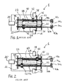
- a splined shaft 10 which is integral with the mechanical shaft 55 to be controlled (shown in schematic form) and actuated by a motor 20 , engages with two gear wheels 12 in turn each engaged by means of a female thread on a threaded spindle 14 on which they are able to move longitudinally in both directions following their own rotation—see FIG. 1 .
- one of the two gear wheels 12 reaches and pushes a control element 16 which operates an electric switch 18 (microswitch), varying the opening/closing condition thereof—cf. the upper switch in FIG. 2 .
- the change of state of the switch 18 is detected by the device 1 and the motor 20 is stopped.
- the other gear wheel 12 instead moves in the opposite direction, if necessary reaching the end of the threaded spindle 14 .
- the device 1 there are two sets of elements for being able to control the two directions of rotation of the mechanical shaft 55 .
- the two threaded spindles 14 extend longitudinally in the form of two rods 70 a , 70 b , at the end of which a gear wheel 72 a , 72 b coaxial therewith is present.
- the wheels 72 a , 72 b are engaged respectively with two endless screws 74 a , 74 b .
- the roller blind By means of the action of the motor, the roller blind is positioned in the desired opening position and, by means of a suitable implement, such as for example a screw driver, and assuming that the upper spindle 14 is used for adjusting the opening end-of-travel position, the endless screw 74 a is turned until, by means of rotation of the rod 70 a and therefore the upper spindle 14 , the upper gear wheel 12 trips the upper switch 18 , which causes stoppage of the motor 20 .
- the subsequent displacement of the roller blind into the closing position and the consequent definition of the position in which the lower gear wheel 12 trips the lower switch 18 causes movement of the upper gear wheel 12 away from the upper switch 18 into a position determined by actuation of the closing end-of-travel stop.
- This latter position may vary depending on the type of shutter or curtain on which the motor has been mounted and depending on the requirements of the individual user.
- the motor Upon subsequent opening of the roller blind, the motor will run until one of the wheels 12 actuates one of the switches 18 . Therefore the rest (or non-operative) position of the upper and lower wheels 12 may be situated anywhere along the spindle 14 and may be different depending on the adjustments made.
- the screws 74 a,b keep the spindles 14 fixed.
- the device 1 may be improved, so as to comprise a smaller number of parts, resulting in advantages in terms of weight, lesser complexity and lower cost.
- the object of the present invention is to improve the state of the art. This object is achieved with use of a device for interrupting selectively a rotary translational movement in accordance with the following claims.
- FIG. 1 shows a schematic cross-sectional view of a device according to the state of the art in a first position
- FIG. 2 shows a schematic view of the device according to FIG. 1 in a second position
- FIG. 3 shows a schematic cross-sectional view of a device which comprises the present invention, in a first position
- FIG. 4 shows a schematic view of the device according to FIG. 3 in a second position
- FIG. 5 shows a detail of the device according to the present invention
- FIG. 6 shows a detail of a variant of the device according to the present invention.
- FIG. 7 shows an enlarged view of a detail contained in the inset Q of FIG. 6 ;
- FIG. 8 shows a detail of another variant of the device according to the present invention.
- FIG. 9 shows a detail of another variant of the device according to the present invention.
- FIG. 10 shows a detail of another variant of the device according to the present invention.
- FIG. 11 shows a schematic cross-sectional view of a variant of the device shown in FIG. 3 , in a first position
- FIG. 12 shows a schematic view of the device shown in FIG. 11 , in a second position.
- the reference number 100 denotes a limiting device which is based on and improves the abovementioned device 1 , the numbering of which is maintained with the addition of a suffix “1” for similar elements.
- the limiting device 100 therefore comprises a splined shaft 110 , integral with the shaft 155 to be controlled (shown schematically) and actuated by a motor 120 .
- Said shaft 110 engages with two gear wheels 112 each of which is in turn engaged by means of a female thread on a threaded spindle 114 , said shaft 110 being supported by two support flanges 150 .
- said wheels 112 may move axially on said spindle 114 in both directions following rotation thereof—cf. FIGS.
- a characteristic of the limiting device 100 due to the special features of the present invention—is the absence of the springs 22 existing in the known art, resulting in the undoubted saving of material and greater simplicity in terms of production and assembly.
- the wheels 112 In order to prevent the wheels 112 from being forced beyond the thread of the threaded spindles 114 , no longer managing to engage therewith so as to move in the opposite direction, they are cut along a radius—see FIG. 5 where the cut has the reference number 113 . In the case where they are made of plastic, this is achieved without difficulty.
- the distance between the flanges 150 and the end 115 of the thread on the spindles 114 is kept less than the thickness of the gear wheels 112 : in this way said wheels 112 are stopped by the flanges 150 before they are able to disengage definitively from the thread on the spindles 114 and, owing to the cut along their radius, they are deformed and splay slightly, rotating idle (see FIG. 4 ). With reversal in the direction of the motor 120 , the wheel 112 reverses its direction of rotation and, engaging again on the thread of the spindle 114 , moves away from the adjacent flange 150 .
- a second characteristic feature of the present invention is to make all the rotating parts preferably from plastic, in particular the gear wheels 122 and the threaded spindles 114 .
- these parts may be made by means of moulding, in an efficient and cost-effective manner (plastic has a lower cost and moulding parts from plastic is a less costly process).
- An alternative solution may be to manufacture the abovementioned components from soft plastic or rubber, such that it is not required to cut them in order to obtain the necessary deformation.
- FIGS. 11 and 12 show a variant 1000 of the limiting device 100 , in which the same reference numbers used in FIGS. 3 and 4 are maintained for identical parts and the end-of-travel adjustment mechanism (the two rods 170 a , 170 b , the gear wheels 172 a , 172 b and the two endless screws 174 a , 174 b ) are not shown.
- the control elements 116 have an L shape and slide inside an opening of the support flange 150 .
- the electrical switches 118 are arranged outside the flanges 150 and are actuated (see upper switch in FIG. 12 ) by one end 116 b of the elements 116 .
- the rest of the device is functionally identical to the previous device.
- the cut 113 in the gear wheel 112 may be not only linear (see FIG. 5 ) but also have a different progression, for example a V-shaped progression (see FIG. 10 ) or transverse progression (see FIG. 8 ).
- the configurations of the cut 113 shown in FIGS. 8 and 10 are such that one or more teeth of the wheel 112 need not be eliminated completely, improving the grip of the latter on the splined shaft 110 . Grooves with different forms may obviously be envisaged.
- FIGS. 6 and 7 A variant of the invention is shown in FIGS. 6 and 7 .
- it may be sufficient to form a groove 117 therein parallel to the teeth.
- an annular zone 121 of the wheel 112 remains completely in contact with the thread—favouring an optimum grip—but its thickness is somewhat smaller so that it is able to expand when stressed and cause the wheel 112 to disengage from the thread of the spindle 114 .
- FIG. 9 Another solution is shown in FIG. 9 .
- the threaded spindle 114 is formed hollow and with a longitudinal cut 123 which interrupts its cross-section. When the wheel 112 forces the thread of the spindle 114 , the latter gives way, contracting (the cut 123 becomes narrower), and disengages from the wheel 112 . It may also be sufficient merely to cut longitudinally on the spindle 114 , which is not hollow, along a portion of its thread, a groove which is blind or may extend from one side to the other.
- the device for interrupting selectively a rotary translational movement may be applied to other mechanisms, for examples devices for detecting obstacles or brakes.
- the splined shaft 110 may be replaced by a smooth spindle which transmits, via elastic belts, the movement to the wheel 112 .
- the wheel 112 may be smooth instead of having teeth, possibly made of rubber, and in contact with a smooth spindle which causes it to rotate by means of friction. In certain cases it may be convenient to produce these elements using different materials, for example rubber on the outside and an internal thread made of plastic.
Landscapes
- Engineering & Computer Science (AREA)
- General Engineering & Computer Science (AREA)
- Mechanical Engineering (AREA)
- Transmission Devices (AREA)
- Glass Compositions (AREA)
- Machine Translation (AREA)
- Non-Portable Lighting Devices Or Systems Thereof (AREA)
- Lighting Device Outwards From Vehicle And Optical Signal (AREA)
- Operating, Guiding And Securing Of Roll- Type Closing Members (AREA)
Applications Claiming Priority (4)
| Application Number | Priority Date | Filing Date | Title |
|---|---|---|---|
| ITTV2004U00036 | 2004-08-04 | ||
| IT000036U ITTV20040036U1 (it) | 2004-08-04 | 2004-08-04 | Dispositivo per interrompere selettivamente un moto di rototraslazione. |
| ITTV20040036U | 2004-08-04 | ||
| PCT/EP2005/053607 WO2006013172A1 (en) | 2004-08-04 | 2005-07-25 | Device for interrupting selectively a rotary translational movement |
Related Parent Applications (1)
| Application Number | Title | Priority Date | Filing Date |
|---|---|---|---|
| PCT/EP2005/053607 Continuation WO2006013172A1 (en) | 2004-08-04 | 2005-07-25 | Device for interrupting selectively a rotary translational movement |
Publications (2)
| Publication Number | Publication Date |
|---|---|
| US20070147972A1 US20070147972A1 (en) | 2007-06-28 |
| US8033193B2 true US8033193B2 (en) | 2011-10-11 |
Family
ID=34981700
Family Applications (1)
| Application Number | Title | Priority Date | Filing Date |
|---|---|---|---|
| US11/700,221 Expired - Fee Related US8033193B2 (en) | 2004-08-04 | 2007-01-30 | Device for interrupting selectively a rotary translational movement |
Country Status (11)
| Country | Link |
|---|---|
| US (1) | US8033193B2 (de) |
| EP (1) | EP1774200B1 (de) |
| CN (1) | CN100482972C (de) |
| AT (1) | ATE408081T1 (de) |
| AU (1) | AU2005268829B2 (de) |
| DE (1) | DE602005009709D1 (de) |
| ES (1) | ES2313378T3 (de) |
| IT (1) | ITTV20040036U1 (de) |
| PL (1) | PL1774200T3 (de) |
| RU (1) | RU2340817C1 (de) |
| WO (1) | WO2006013172A1 (de) |
Cited By (1)
| Publication number | Priority date | Publication date | Assignee | Title |
|---|---|---|---|---|
| US20150001999A1 (en) * | 2013-06-26 | 2015-01-01 | Aktiebolaget Skf | Actuator |
Families Citing this family (2)
| Publication number | Priority date | Publication date | Assignee | Title |
|---|---|---|---|---|
| WO2011057640A1 (en) * | 2009-11-12 | 2011-05-19 | Lego A/S | A toy building set with an overload-safe linear actuator |
| CN103288004B (zh) * | 2013-05-29 | 2016-04-27 | 杭州恒宏机械有限公司 | 防堵转齿轮箱 |
Citations (11)
| Publication number | Priority date | Publication date | Assignee | Title |
|---|---|---|---|---|
| GB779420A (en) | 1955-03-09 | 1957-07-17 | Bronzavia Sa | Improvements in or relating to screw and nut transmission devices |
| US3277737A (en) | 1964-07-27 | 1966-10-11 | Goodman Robert | Device for translating rotary motion into linear motion |
| US3718215A (en) | 1970-01-19 | 1973-02-27 | Carpano & Pons | Device for limiting the number of revolution of a rotating shaft |
| US4482211A (en) * | 1982-12-13 | 1984-11-13 | Robert J. Fisher | Electrically operated remote control rearview mirror |
| US5027671A (en) | 1990-06-18 | 1991-07-02 | Kerk Motion Products, Inc. | Reinforced anti-backlash nut |
| JPH0478359A (ja) | 1990-07-21 | 1992-03-12 | Tsuoisu Kk | 遊星歯車装置用トルクリミッター |
| US5450988A (en) | 1994-07-18 | 1995-09-19 | Wagner Spray Tech Corporation | Powered caulking gun |
| FR2730022A1 (fr) | 1995-01-31 | 1996-08-02 | Ymos France | Mecanisme a engrenage a amortissement de chocs de fin de course |
| JPH11270645A (ja) | 1998-03-20 | 1999-10-05 | Matsushita Electric Ind Co Ltd | 螺合装置 |
| US20020046817A1 (en) | 2000-04-11 | 2002-04-25 | Last Harry J. | Automatic pool cover system using buoyant-slat pool covers |
| US6789909B2 (en) * | 2001-12-12 | 2004-09-14 | Kabushiki Kaisha Tokai-Rika-Denki | Mirror device for vehicle |
Family Cites Families (1)
| Publication number | Priority date | Publication date | Assignee | Title |
|---|---|---|---|---|
| DE10203385A1 (de) * | 2002-01-29 | 2003-08-07 | Trw Automotive Electron & Comp | Baugruppe aus Spindel und Bewegungsmutter |
-
2004
- 2004-08-04 IT IT000036U patent/ITTV20040036U1/it unknown
-
2005
- 2005-07-25 DE DE602005009709T patent/DE602005009709D1/de not_active Expired - Lifetime
- 2005-07-25 PL PL05763066T patent/PL1774200T3/pl unknown
- 2005-07-25 WO PCT/EP2005/053607 patent/WO2006013172A1/en not_active Ceased
- 2005-07-25 EP EP05763066A patent/EP1774200B1/de not_active Expired - Lifetime
- 2005-07-25 AT AT05763066T patent/ATE408081T1/de not_active IP Right Cessation
- 2005-07-25 CN CNB2005800265779A patent/CN100482972C/zh not_active Expired - Fee Related
- 2005-07-25 RU RU2007107925/11A patent/RU2340817C1/ru not_active IP Right Cessation
- 2005-07-25 AU AU2005268829A patent/AU2005268829B2/en not_active Ceased
- 2005-07-25 ES ES05763066T patent/ES2313378T3/es not_active Expired - Lifetime
-
2007
- 2007-01-30 US US11/700,221 patent/US8033193B2/en not_active Expired - Fee Related
Patent Citations (11)
| Publication number | Priority date | Publication date | Assignee | Title |
|---|---|---|---|---|
| GB779420A (en) | 1955-03-09 | 1957-07-17 | Bronzavia Sa | Improvements in or relating to screw and nut transmission devices |
| US3277737A (en) | 1964-07-27 | 1966-10-11 | Goodman Robert | Device for translating rotary motion into linear motion |
| US3718215A (en) | 1970-01-19 | 1973-02-27 | Carpano & Pons | Device for limiting the number of revolution of a rotating shaft |
| US4482211A (en) * | 1982-12-13 | 1984-11-13 | Robert J. Fisher | Electrically operated remote control rearview mirror |
| US5027671A (en) | 1990-06-18 | 1991-07-02 | Kerk Motion Products, Inc. | Reinforced anti-backlash nut |
| JPH0478359A (ja) | 1990-07-21 | 1992-03-12 | Tsuoisu Kk | 遊星歯車装置用トルクリミッター |
| US5450988A (en) | 1994-07-18 | 1995-09-19 | Wagner Spray Tech Corporation | Powered caulking gun |
| FR2730022A1 (fr) | 1995-01-31 | 1996-08-02 | Ymos France | Mecanisme a engrenage a amortissement de chocs de fin de course |
| JPH11270645A (ja) | 1998-03-20 | 1999-10-05 | Matsushita Electric Ind Co Ltd | 螺合装置 |
| US20020046817A1 (en) | 2000-04-11 | 2002-04-25 | Last Harry J. | Automatic pool cover system using buoyant-slat pool covers |
| US6789909B2 (en) * | 2001-12-12 | 2004-09-14 | Kabushiki Kaisha Tokai-Rika-Denki | Mirror device for vehicle |
Non-Patent Citations (1)
| Title |
|---|
| International Search Report and the Written Opinion of the International Searching Authority mailed Oct. 26, 2005. |
Cited By (2)
| Publication number | Priority date | Publication date | Assignee | Title |
|---|---|---|---|---|
| US20150001999A1 (en) * | 2013-06-26 | 2015-01-01 | Aktiebolaget Skf | Actuator |
| US9735657B2 (en) * | 2013-06-26 | 2017-08-15 | Aktiebolaget Skf | Actuator |
Also Published As
| Publication number | Publication date |
|---|---|
| CN1993573A (zh) | 2007-07-04 |
| CN100482972C (zh) | 2009-04-29 |
| ES2313378T3 (es) | 2009-03-01 |
| ITTV20040036U1 (it) | 2004-11-04 |
| DE602005009709D1 (de) | 2008-10-23 |
| EP1774200A1 (de) | 2007-04-18 |
| RU2340817C1 (ru) | 2008-12-10 |
| ATE408081T1 (de) | 2008-09-15 |
| AU2005268829A2 (en) | 2006-02-09 |
| AU2005268829B2 (en) | 2010-10-28 |
| PL1774200T3 (pl) | 2009-02-27 |
| RU2007107925A (ru) | 2008-09-10 |
| WO2006013172A1 (en) | 2006-02-09 |
| EP1774200B1 (de) | 2008-09-10 |
| US20070147972A1 (en) | 2007-06-28 |
| AU2005268829A1 (en) | 2006-02-09 |
Similar Documents
| Publication | Publication Date | Title |
|---|---|---|
| US5044417A (en) | Roller assemblies for automatically winding and unwinding closures | |
| CA2656981C (en) | Dual roll blind system | |
| US8033193B2 (en) | Device for interrupting selectively a rotary translational movement | |
| US8281677B2 (en) | Electromotive linear drive | |
| CN111247048B (zh) | 用于机动车辆的转向柱 | |
| EP3329580B1 (de) | Bremsvorrichtung für einen elektrischen antriebsmotor | |
| US8286685B2 (en) | Limit mechanism of upper stop level and lower stop level for rolling door | |
| ITMI980957A1 (it) | Veicolo con almeno una porta scorrevole e un comando della porta scorrevole | |
| US6880424B2 (en) | Apparatus for telescoping actuator | |
| DE4105157C2 (de) | Schaltvorrichtung | |
| JP2011062497A (ja) | カーテン装置 | |
| RU2373362C2 (ru) | Конечное устройство перемещения для систем привода рольставней или светозащитных навесов | |
| EP2060206A2 (de) | Möbelantrieb | |
| JPH07217311A (ja) | 終点位置の間で可動な車輌部材の駆動装置 | |
| EP2147615A1 (de) | Drehantrieb | |
| EP2935747A1 (de) | Linearantrieb, insbesondere für schiebetüren und schiebeverschlusselemente im allgemeinen | |
| EP3663133B1 (de) | Kraftfahrzeugscheinwerfereinstellmechanismus mit kupplung | |
| US6668679B2 (en) | Apparatus and method for pulley actuator | |
| US5111925A (en) | Device for automatically halting an electric motor after a certain number of revolutions | |
| EP3237768B1 (de) | Kompensationsvorrichtung | |
| DE602004004696T2 (de) | Getriebe mit einer Schneckenwelle für Rolladen | |
| KR101776205B1 (ko) | 블라인드의 쉐이드 구동 장치 | |
| CN107624093A (zh) | 凸轮锁定机构和相关的转向柱 | |
| JP2859074B2 (ja) | スイッチ機構の基準位置設定装置および基準位置設定方法 | |
| WO2007016840A1 (en) | An automatic stepless transmission |
Legal Events
| Date | Code | Title | Description |
|---|---|---|---|
| AS | Assignment |
Owner name: NICE SPA, ITALY Free format text: ASSIGNMENT OF ASSIGNORS INTEREST;ASSIGNOR:MALAUSA, ANDREA;REEL/FRAME:018868/0394 Effective date: 20070118 |
|
| STCF | Information on status: patent grant |
Free format text: PATENTED CASE |
|
| FPAY | Fee payment |
Year of fee payment: 4 |
|
| FEPP | Fee payment procedure |
Free format text: MAINTENANCE FEE REMINDER MAILED (ORIGINAL EVENT CODE: REM.); ENTITY STATUS OF PATENT OWNER: LARGE ENTITY |
|
| LAPS | Lapse for failure to pay maintenance fees |
Free format text: PATENT EXPIRED FOR FAILURE TO PAY MAINTENANCE FEES (ORIGINAL EVENT CODE: EXP.); ENTITY STATUS OF PATENT OWNER: LARGE ENTITY |
|
| STCH | Information on status: patent discontinuation |
Free format text: PATENT EXPIRED DUE TO NONPAYMENT OF MAINTENANCE FEES UNDER 37 CFR 1.362 |
|
| FP | Lapsed due to failure to pay maintenance fee |
Effective date: 20191011 |