US8035985B2 - Avionics rack arrangement - Google Patents
Avionics rack arrangement Download PDFInfo
- Publication number
- US8035985B2 US8035985B2 US12/365,433 US36543309A US8035985B2 US 8035985 B2 US8035985 B2 US 8035985B2 US 36543309 A US36543309 A US 36543309A US 8035985 B2 US8035985 B2 US 8035985B2
- Authority
- US
- United States
- Prior art keywords
- electronic equipment
- interface
- connectors
- rack
- equipment rack
- Prior art date
- Legal status (The legal status is an assumption and is not a legal conclusion. Google has not performed a legal analysis and makes no representation as to the accuracy of the status listed.)
- Expired - Fee Related, expires
Links
- 230000003287 optical effect Effects 0.000 claims description 17
- 230000004224 protection Effects 0.000 claims description 9
- 238000001816 cooling Methods 0.000 claims description 8
- 238000009413 insulation Methods 0.000 claims description 4
- 239000011295 pitch Substances 0.000 claims description 4
- 239000000835 fiber Substances 0.000 claims description 2
- 238000012423 maintenance Methods 0.000 abstract description 18
- 238000010586 diagram Methods 0.000 description 9
- 230000007547 defect Effects 0.000 description 3
- 238000005204 segregation Methods 0.000 description 2
- 230000002457 bidirectional effect Effects 0.000 description 1
- 230000015556 catabolic process Effects 0.000 description 1
- 239000002826 coolant Substances 0.000 description 1
- 238000006731 degradation reaction Methods 0.000 description 1
- 230000000694 effects Effects 0.000 description 1
- 230000006872 improvement Effects 0.000 description 1
- 238000012986 modification Methods 0.000 description 1
- 230000004048 modification Effects 0.000 description 1
- 239000013307 optical fiber Substances 0.000 description 1
- 230000008520 organization Effects 0.000 description 1
- 238000013021 overheating Methods 0.000 description 1
- 230000003014 reinforcing effect Effects 0.000 description 1
- 238000006467 substitution reaction Methods 0.000 description 1
- 230000009897 systematic effect Effects 0.000 description 1
- 238000011144 upstream manufacturing Methods 0.000 description 1
Images




Classifications
-
- H—ELECTRICITY
- H05—ELECTRIC TECHNIQUES NOT OTHERWISE PROVIDED FOR
- H05K—PRINTED CIRCUITS; CASINGS OR CONSTRUCTIONAL DETAILS OF ELECTRIC APPARATUS; MANUFACTURE OF ASSEMBLAGES OF ELECTRICAL COMPONENTS
- H05K7/00—Constructional details common to different types of electric apparatus
- H05K7/14—Mounting supporting structure in casing or on frame or rack
- H05K7/1438—Back panels or connecting means therefor; Terminals; Coding means to avoid wrong insertion
- H05K7/1447—External wirings; Wiring ducts; Laying cables
- H05K7/1449—External wirings; Wiring ducts; Laying cables with connections to the back board
-
- H—ELECTRICITY
- H05—ELECTRIC TECHNIQUES NOT OTHERWISE PROVIDED FOR
- H05K—PRINTED CIRCUITS; CASINGS OR CONSTRUCTIONAL DETAILS OF ELECTRIC APPARATUS; MANUFACTURE OF ASSEMBLAGES OF ELECTRICAL COMPONENTS
- H05K7/00—Constructional details common to different types of electric apparatus
- H05K7/14—Mounting supporting structure in casing or on frame or rack
- H05K7/1438—Back panels or connecting means therefor; Terminals; Coding means to avoid wrong insertion
- H05K7/1447—External wirings; Wiring ducts; Laying cables
- H05K7/1448—External wirings; Wiring ducts; Laying cables with connections to the front board
Definitions
- the present invention relates to an electronic equipment rack arrangement principle, and more particularly an avionics rack arrangement principle.
- the aim of this arrangement is notably to allow for the maximum use of COTS (component off the shelf) modules or, at least, a maximum of “standardized” modules, if possible independent of the type of aircraft, primarily with regard to the electronic functions of said avionics rack. It also enables all the maintenance operations performed on a rack arranged according to the invention to be able to be done via the front panel of said rack, all of its component modules being made accessible from this side.
- an electronic equipment rack is made up of a mechanical structure comprising a motherboard, electronic equipment handling a set of functions and combined under the designation of function modules, and interface elements allowing for the link with an environment, for example the rest of the aircraft in the case of an avionics rack.
- Such electronic equipment generally comprises boards or “single replaceable units” (SRU).
- An electronic equipment rack also comprises internal connectors enabling the motherboard, the electronic equipment and the interface modules to be interconnected, and external connectors enabling the link with the environment of said rack.
- the subject of the invention is an electronic equipment rack, designed to be on board a craft such as an aircraft, and comprising:
- the function module and the interface module are stacked.
- the first cabinet can comprise integrated cooling means, notably for cooling the electronic equipment.
- the second cabinet is shorter than the first cabinet in a direction orthogonal to the front panel of the rack.
- the interface module is sufficiently shorter than the function module for a free space contiguous to the interface module to be available between the front panel of the rack and said interface module.
- the motherboard is located on the side of the rear panel of the rack, the function and interface modules being connected to it, and in that the external connectors linked to the interface module are located on the side of the front panel of the electronic equipment rack.
- An electronic equipment rack according to the invention comprises:
- the function module comprises “off-the-shelf” electronic equipment (otherwise referred to as COTS, standing for “components off the shelf”).
- the function module and the interface module have different pitches.
- all or some of the external connectors linked to the interface module can meet one of the following specifications: ARINC 600, ARINC 404 A, MIL 83 527, EN4640, EN4165.
- all or some of the external connectors linked to the interface module can be fibre optic connectors.
- the electronic equipment rack comprises from one to several interface modules linked to one or more function modules.
- the interface module comprises an optical star-type element enabling the distribution of optical signals, notably in the environment of the electronic equipment rack.
- said optical star-type element may be passive.
- an avionics rack on board an aircraft can be made up of at least one electronic equipment rack according to the invention.
- an avionics rack can comprise an interface module including a filter-type protection function, suited to said aircraft.
- an avionics rack can comprise an interface module including a lightning-protection function, suited to said aircraft.
- an avionics rack can comprise protection and insulation functions between the “aircraft wiring” and the function module.
- the interface module comprises transformer- or fuse-type elements handling said protection and insulation functions between the “aircraft wiring” and the function module.
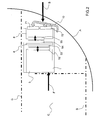
- FIG. 1 the diagram of a first possible electronic equipment rack configuration according to the state of the art
- FIG. 2 the diagram of a second possible electronic equipment rack configuration according to the state of the art
- FIG. 3 the diagram of a third possible electronic equipment rack configuration according to the state of the art
- FIG. 4 the diagram of a possible optimized configuration for electronic equipment racks, according to the invention.
- FIG. 5 a the simplified diagram of an electronic equipment rack arranged according to the invention, highlighting a free area at the heart of the rack,
- FIG. 5 b the illustration of the possibility of having a wide free area enabling the signals to be sorted and distributed according to the pattern of a motherboard and its internal connectors in an electronic equipment rack configured according to the invention
- FIG. 6 the diagram of an electronic equipment rack according to the invention, having internal and external optical connectors.
- FIG. 1 shows a diagram of a partial section of an aircraft comprising an electronic equipment rack.
- the aircraft comprises a wall A, a cargo area C and, between the two, an area in which avionics racks can be installed.
- the passenger deck is represented by the identifier G, and the floor of the cargo area by the identifier S.
- the arrow F indicates the front panel of the rack whereas the arrow B indicates the rear panel.
- the rack comprises a mechanical structure 1 that is often called “back”, a motherboard 6 , function modules 3 , consisting of different SRUs or electronic equipment.
- the internal connectors 50 on the side of the function modules 3 , and 51 , on the side of the motherboard 6 , enable the various electronic equipment items of the function modules 3 to be inter-connected, via the motherboard 6 , and the wiring 10 , connected to the external connectors 71 and 72 and providing the link with the rest of the aircraft.
- the interface functions between the electronic equipment and the rest of the aeroplane are not independent of the function modules 3 .
- passive interface elements such as lightning protections or filters are generally necessary and specific to each aircraft.
- the introduction of these interface functions within the electronic functions of the function modules 3 makes it almost impossible to use electronic equipment of COTS type or “standardized” electronic equipment, that is, equipment that is compatible with different aircraft or widely distributed.
- the topology associated with this configuration means there is a need to disconnect the “aircraft wiring” 10 from the connectors 71 , 72 to be able to access the function modules 3 in the context of a maintenance operation on the electronic equipment. Such maintenance operations, which are frequent, are therefore slowed down.
- FIG. 2 shows a second possible configuration of an avionics rack according to the state of the art.
- the rack of FIG. 2 comprises interface modules 8 for which the interconnection with the motherboard 6 and the function modules 3 is provided by means of second internal connectors 54 , 55 . It thus becomes possible to use a maximum of COTS-type or “standardized” electronic equipment to construct the function modules 3 .
- the interface functions comprising the specific elements such as the lightning protections, are handled by the interface modules 8 .
- the interface modules 8 are located on the side of the rear panel B of the rack.
- the external connectors 71 , 72 enabling the connection of the “aircraft wiring” 10 are on the side of the rear panel B of the rack.
- the “aircraft wiring” 10 situated on the side of the wall A, becomes difficult to access. This also complicates any maintenance operation on the interface modules 8 .
- this type of maintenance is less frequent than the maintenance on the electronic equipment of the function modules 3 , it is still regular.
- this configuration increases the depth of the rack because of the addition of the interface modules 8 on the side of the rear panel B.
- the space needed between the cargo area C and the wall A of the aircraft is therefore increased.
- FIG. 3 represents a third example of avionics rack configuration that exists in the current state of the art.
- an interface board 9 can be connected to the motherboard 6 on the side of the rear panel B of the rack. This means that, because of the geometry chosen for the motherboard 6 and the interface board 9 , it is possible to have external connectors 71 on the side of the front panel F of the rack.
- the interface board 9 connected to the motherboard 6 , is in an intermediate position between the function modules 3 and the aircraft.
- this interface board 9 increases the depth of the rack, meaning that more space is needed between the cargo area C and the wall 3 . Furthermore, a maintenance operation on such an interface board 9 , located on the side of the rear panel B of the rack, is complex and costly in time.
- FIG. 4 illustrates one example thereof.
- This electronic equipment rack presents an original topology, in which the function modules 3 and the interface modules 8 are juxtaposed in a direction orthogonal to the normal to the front panel F of the rack.
- This topology notably makes it possible to minimize the distance between the front panel F and the rear panel B of the rack.
- it is a vertical topology.
- the interface modules 8 are here located under the function modules 3 . It should be noted that it would conversely be possible to have the interface modules 8 above the function modules 3 while retaining the same type of vertical topology.
- the function modules 3 and the interface modules 8 can be juxtaposed side-by-side.
- the second internal connectors 54 , 55 enable the interface modules 8 and the motherboard 6 to be interconnected whereas the first internal connectors 52 , 53 enable the function modules 3 and the motherboard 6 to be interconnected.
- the motherboard 6 totally passive, supports only the internal connectors 53 , 55 .
- the structure of the rack comprises two “backs” or cabinets 1 and 2 .
- the first cabinet 1 is designed to receive the function modules 3 comprising electronic equipment, for example SRUs.
- Such electronic equipment can be independent of the type of aircraft for which the avionics rack is intended. They are, moreover, directly accessible via the front panel F of the rack, which facilitates the maintenance operations on the function modules 3 .
- the first cabinet 1 can comprise cooling elements designed to avoid any unwanted overheating of the electronic equipment. This cooling can be provided by a circulation of coolant or by forced air distribution, for example.
- first cabinet 1 Under the first cabinet 1 , there is a second cabinet 2 , housing the interface modules 8 .
- an interface module 8 is shorter and less bulky than a function module 3 , because it is less complex. Consequently, the second cabinet 2 is shorter than the first cabinet 1 . Since the two cabinets 1 , 2 are aligned on the side of the rear panel B of the rack, a space is made available upstream of the second cabinet 2 , on the side of the front panel F of the rack. This space enables the “aeroplane wiring” 10 , connected to the external connectors 71 , 72 , not to extend beyond the front panel F of the rack, which shelters it from any mechanical degradations and/or facilitates the fitting of a possible reinforcing plate on the front panel F of the rack.
- the pitches and the thicknesses of the function modules 3 can differ from those of the interface modules 8 .
- the interface modules 8 adapt best to the external connectors 71 , 72 of the aircraft and can provide for a continuity of the segregation routes of the aircraft as far as the modules.
- the function modules 3 can comprise COTS-type or “standardized” electronic equipment.
- the interconnection between the function modules 3 and the interface modules 8 is provided by the internal connectors 52 , 53 , 54 , 55 .
- the maintenance of the interface modules 8 may require the disconnection of the “aircraft wiring” 10 , but access to said interface modules 8 is via the front panel F of the rack. Furthermore, it should be noted that the maintenance operations on the interface modules 8 are generally less frequent than on the function modules 3 , notably because of the passivity of the interface modules 8 that consequently dissipate no, or little, power.
- This vertical organization makes a free area 30 available between the interface area 40 and the processing area 20 within the rack, between the function modules 3 , the interface modules 8 and the motherboard 6 .
- FIGS. 5 a and 5 b show.
- the length La of the external connectors 71 , 72 , to which the “aircraft wiring” 10 is connected is conventionally greater than the length Li of the second internal connectors 54 , which allows for connection between the interface modules 8 and the motherboard 6 .
- a free area 30 of length Lf appears between the processing area 20 of length Lt, corresponding to the area of interconnection between the function modules 3 and the motherboard 6 , and the interface area 40 of length Li, corresponding to the area of interconnection between the interface modules 8 and the motherboard 6 .
- this free space 30 represented in FIG. 5 b enables the signals to be sorted and distributed between the interface area 40 at the input/output of the interface modules 8 and the processing area 20 , at the input/output of the function modules 3 .
- FIG. 6 shows the diagram of a variant of avionics rack arranged according to the invention.
- this variant has external optical connectors 73 , and the internal optical connectors 57 between the interface modules 8 and the motherboard 6 and the internal optical connectors 56 between the function modules 3 and the motherboard 6 .
- This makes it possible to connect an optical fibre 11 originating from the aircraft containing the rack.
- optical bus link cables bidirectional or otherwise, are incorporated on the motherboard 6 .
- This optical link enables one or more interface modules 8 to be interconnected with one or more function modules 3 with no limitation other than the capacity of the optical connectors.
- interface modules 8 can include “optical stars”, preferably passive, but possibly active, enabling optical signals to be redistributed in the environment of the rack.
- an electronic equipment rack makes the following easy:
- the vertical topology is also particularly well suited to the volume available between the wall A and the cargo area C of an aircraft.
- this volume is generally narrow, meaning there is a short distance between the front F and rear B panels of the rack, and relatively high, notably allowing the vertical configuration of the rack of the present patent application.
- the decoupling between the electronic functions handled by the function modules 3 and the interface functions handled by the interface modules 8 makes it possible to observe the segregation rules as far as the electronics level and, where appropriate, as far as the signals on the optical buses.
- This decoupling also makes it possible to maximize the use of COTS-type electronic modules, or at least of “standardized” electronic modules, to construct the function modules 3 .
- the function 3 and interface 8 modules can, because they are decoupled, have different pitches, which makes it possible to optimize the adaptability of an electronic equipment rack to any type of equipment or aircraft for which it is intended.
- the mechanical structure 1 , 2 of an electronic equipment rack according to the invention is totally passive: it supports only the connectors and any cooling devices. Consequently, this mechanical structure 1 , 2 can become totally standard and be useable on different types of aeroplane, for example.
- This passivity of the mechanical structure 1 , 2 renders the maintenance operations on it almost pointless. Only mechanical breaks require intervention. Another consequence is that it becomes possible to ensure the mechanical strength of the structure 1 , 2 of the rack in a rigid way, on the wall of an aircraft for example: in practice, it will potentially never be necessary to dismantle said rack. Thanks to that, any cooling devices inserted into the mechanical structure 1 , 2 can have their reliability increased, in the absence of frequent dismantling/reassembly of the rack.
Landscapes
- Engineering & Computer Science (AREA)
- Microelectronics & Electronic Packaging (AREA)
- Mounting Of Printed Circuit Boards And The Like (AREA)
- Cooling Or The Like Of Electrical Apparatus (AREA)
Applications Claiming Priority (2)
| Application Number | Priority Date | Filing Date | Title |
|---|---|---|---|
| FR0800584 | 2008-02-05 | ||
| FR0800584A FR2927222B1 (fr) | 2008-02-05 | 2008-02-05 | Arrangement de rack avionique |
Publications (2)
| Publication Number | Publication Date |
|---|---|
| US20090195135A1 US20090195135A1 (en) | 2009-08-06 |
| US8035985B2 true US8035985B2 (en) | 2011-10-11 |
Family
ID=39789863
Family Applications (1)
| Application Number | Title | Priority Date | Filing Date |
|---|---|---|---|
| US12/365,433 Expired - Fee Related US8035985B2 (en) | 2008-02-05 | 2009-02-04 | Avionics rack arrangement |
Country Status (3)
| Country | Link |
|---|---|
| US (1) | US8035985B2 (fr) |
| CA (1) | CA2652746C (fr) |
| FR (1) | FR2927222B1 (fr) |
Cited By (6)
| Publication number | Priority date | Publication date | Assignee | Title |
|---|---|---|---|---|
| US20110127379A1 (en) * | 2008-02-25 | 2011-06-02 | Airbus Operations Gmbh | Modular Device Holder |
| US20120285950A1 (en) * | 2011-04-26 | 2012-11-15 | Airbus Operations (S.A.S.) | Electrical power distribution unit and a vehicle having such a unit |
| US9572276B2 (en) | 2014-11-06 | 2017-02-14 | Cinnos Technologies, Inc. | Smart mission critical rack |
| US9656618B2 (en) | 2011-09-30 | 2017-05-23 | Airbus Operations S.A.S | Electrical cabinet of an aircraft incorporating an improved electrical connection system |
| US9999147B1 (en) | 2017-01-31 | 2018-06-12 | Airbus Americas Engineering, Inc. | Dummy line replaceable unit |
| US10826210B2 (en) * | 2016-11-10 | 2020-11-03 | Airbus Operations Gmbh | Base module and aviation computer system having the base module |
Families Citing this family (18)
| Publication number | Priority date | Publication date | Assignee | Title |
|---|---|---|---|---|
| FR2934906B1 (fr) * | 2008-08-05 | 2010-09-03 | Thales Sa | Calculateur embarque equipe d'un dispositif de refroidissement aeraulique autonome |
| FR2956279B1 (fr) * | 2010-02-05 | 2013-01-04 | Airbus Operations Sas | Ensemble de connexion a cablage frontal d'au moins un equipement electronique dans un aeronef |
| FR2956278A1 (fr) * | 2010-02-05 | 2011-08-12 | Airbus Operations Sas | Ensemble de connexion d'au moins un equipement electronique dans un aeronef |
| FR2963198B1 (fr) * | 2010-07-21 | 2018-02-16 | Thales | Circuit imprime possedant des pistes protegees, calculateur et procede |
| US8976531B2 (en) * | 2011-01-05 | 2015-03-10 | The Boeing Company | Translating equipment rack system |
| FR2977446B1 (fr) * | 2011-07-01 | 2014-11-28 | Airbus Operations Sas | Cabinet electronique a connexion frontale sur carte fond de panier |
| FR2977447B1 (fr) * | 2011-07-01 | 2014-04-04 | Airbus Operations Sas | Cabinet electronique a connexion laterale |
| US9156553B1 (en) * | 2011-12-02 | 2015-10-13 | The Boeing Company | Aircraft mission equipment having an integrated air caster handling system |
| US9179570B2 (en) * | 2012-07-31 | 2015-11-03 | Simmonds Precision Products, Inc. | Multi connector interconnect system |
| FR3007239B1 (fr) * | 2013-06-15 | 2017-11-17 | Latelec | Procede d'integration de module d'interconnexion amovible dans un meuble, meuble ainsi equipe et aeronef comportant une baie constituee de tels meubles |
| EP3024309B1 (fr) * | 2014-11-21 | 2018-02-28 | Airbus Operations GmbH | Système d'installation électronique, aéronef ou engin spatial et procédé |
| FR3036919B1 (fr) * | 2015-05-29 | 2017-06-16 | Airbus Operations Sas | Equipement electronique comportant un boitier et au moins une carte electronique protegee contre la foudre |
| FR3040582B1 (fr) * | 2015-08-31 | 2017-10-06 | Thales Sa | Calculateur avionique et procede de montage |
| FR3056964B1 (fr) * | 2016-09-30 | 2021-10-08 | Safran Electronics & Defense | Aeronef ayant des calculateurs repartis dans le fuselage |
| FR3057112B1 (fr) * | 2016-09-30 | 2018-11-02 | Safran Electronics & Defense | Unite electronique a modules inversables |
| FR3057103B1 (fr) | 2016-09-30 | 2022-11-11 | Safran Electronics & Defense | Dispositif electronique comprenant un module raccorde a un pcb et unite electronique comportant un tel dispositif |
| FR3083048B1 (fr) * | 2018-06-22 | 2021-03-05 | Airbus Operations Sas | Systeme d'interconnexion pour une baie d'un systeme d'un aeronef |
| FR3097403B1 (fr) | 2019-06-11 | 2021-06-04 | Latelec | Baie avionique d’aéronef à plateau d’interconnexion |
Citations (17)
| Publication number | Priority date | Publication date | Assignee | Title |
|---|---|---|---|---|
| US2938686A (en) * | 1957-02-04 | 1960-05-31 | Boeing Co | Aircraft electronic equipment assembly |
| US5949656A (en) | 1994-06-01 | 1999-09-07 | Davox Corporation | Electronic assembly interconnection system |
| FR2783392A1 (fr) | 1998-09-15 | 2000-03-17 | Sextant Avionique | Dispositif de connexion pour un ensemble de structures modulaires porte-cartes electroniques et rack equipe d'un tel dispositif, accueillant un tel ensemble |
| WO2001080574A2 (fr) | 2000-04-13 | 2001-10-25 | Adc Telecommunications, Inc. | Architecture de repartiteur destinee a un systeme de telecommunications |
| FR2822130A1 (fr) | 2001-03-14 | 2002-09-20 | Labinal | Avion comportant un cablage electrique |
| US20030016513A1 (en) * | 2001-07-23 | 2003-01-23 | Mccall James A. | Systems having modules with buffer chips |
| US6529374B2 (en) * | 2001-02-26 | 2003-03-04 | Teac Corporation | Electronic apparatus |
| US6583982B2 (en) * | 2001-06-19 | 2003-06-24 | Xybernaut Corporation | Intrinsically safe enclosure and method |
| US6778381B1 (en) * | 2000-10-18 | 2004-08-17 | Hewlett-Packard Development Company, L.P. | Retractable display module |
| US20050276023A1 (en) * | 2002-12-16 | 2005-12-15 | Network Appliance, Inc. | Universal modular power supply carrier |
| US7145770B1 (en) * | 2003-10-08 | 2006-12-05 | Copan Systems, Inc. | Method and apparatus of packaging disk drives in a data storage system |
| EP1729556A2 (fr) | 2005-05-30 | 2006-12-06 | Eurocopter | Dispositif d'interconnexion reconfigurable de faisceaux électriques |
| US20060274516A1 (en) * | 2005-06-07 | 2006-12-07 | Alstom Transport Sa | Electronic board device comprising a rack and an electronic board chassis for insertion into the rack |
| US7167359B2 (en) * | 2003-12-29 | 2007-01-23 | Sherwood Information Partners, Inc. | System and method for mass storage using multiple-hard-disk-drive enclosure |
| US20070081315A1 (en) * | 2005-08-29 | 2007-04-12 | Mondor Robert M | Configurable IO subsystem |
| US7227744B2 (en) * | 2003-04-25 | 2007-06-05 | Teac Corporation | Data recording device and memory cartridge of data recording device |
| US7473931B1 (en) * | 2002-02-28 | 2009-01-06 | Garmin International, Inc. | System and method for mounting units for an avionic display |
-
2008
- 2008-02-05 FR FR0800584A patent/FR2927222B1/fr active Active
-
2009
- 2009-02-04 US US12/365,433 patent/US8035985B2/en not_active Expired - Fee Related
- 2009-02-05 CA CA2652746A patent/CA2652746C/fr not_active Expired - Fee Related
Patent Citations (17)
| Publication number | Priority date | Publication date | Assignee | Title |
|---|---|---|---|---|
| US2938686A (en) * | 1957-02-04 | 1960-05-31 | Boeing Co | Aircraft electronic equipment assembly |
| US5949656A (en) | 1994-06-01 | 1999-09-07 | Davox Corporation | Electronic assembly interconnection system |
| FR2783392A1 (fr) | 1998-09-15 | 2000-03-17 | Sextant Avionique | Dispositif de connexion pour un ensemble de structures modulaires porte-cartes electroniques et rack equipe d'un tel dispositif, accueillant un tel ensemble |
| WO2001080574A2 (fr) | 2000-04-13 | 2001-10-25 | Adc Telecommunications, Inc. | Architecture de repartiteur destinee a un systeme de telecommunications |
| US6778381B1 (en) * | 2000-10-18 | 2004-08-17 | Hewlett-Packard Development Company, L.P. | Retractable display module |
| US6529374B2 (en) * | 2001-02-26 | 2003-03-04 | Teac Corporation | Electronic apparatus |
| FR2822130A1 (fr) | 2001-03-14 | 2002-09-20 | Labinal | Avion comportant un cablage electrique |
| US6583982B2 (en) * | 2001-06-19 | 2003-06-24 | Xybernaut Corporation | Intrinsically safe enclosure and method |
| US20030016513A1 (en) * | 2001-07-23 | 2003-01-23 | Mccall James A. | Systems having modules with buffer chips |
| US7473931B1 (en) * | 2002-02-28 | 2009-01-06 | Garmin International, Inc. | System and method for mounting units for an avionic display |
| US20050276023A1 (en) * | 2002-12-16 | 2005-12-15 | Network Appliance, Inc. | Universal modular power supply carrier |
| US7227744B2 (en) * | 2003-04-25 | 2007-06-05 | Teac Corporation | Data recording device and memory cartridge of data recording device |
| US7145770B1 (en) * | 2003-10-08 | 2006-12-05 | Copan Systems, Inc. | Method and apparatus of packaging disk drives in a data storage system |
| US7167359B2 (en) * | 2003-12-29 | 2007-01-23 | Sherwood Information Partners, Inc. | System and method for mass storage using multiple-hard-disk-drive enclosure |
| EP1729556A2 (fr) | 2005-05-30 | 2006-12-06 | Eurocopter | Dispositif d'interconnexion reconfigurable de faisceaux électriques |
| US20060274516A1 (en) * | 2005-06-07 | 2006-12-07 | Alstom Transport Sa | Electronic board device comprising a rack and an electronic board chassis for insertion into the rack |
| US20070081315A1 (en) * | 2005-08-29 | 2007-04-12 | Mondor Robert M | Configurable IO subsystem |
Cited By (7)
| Publication number | Priority date | Publication date | Assignee | Title |
|---|---|---|---|---|
| US20110127379A1 (en) * | 2008-02-25 | 2011-06-02 | Airbus Operations Gmbh | Modular Device Holder |
| US20120285950A1 (en) * | 2011-04-26 | 2012-11-15 | Airbus Operations (S.A.S.) | Electrical power distribution unit and a vehicle having such a unit |
| US8749956B2 (en) * | 2011-04-26 | 2014-06-10 | Airbus Operations S.A.S. | Electrical power distribution unit and a vehicle having such a unit |
| US9656618B2 (en) | 2011-09-30 | 2017-05-23 | Airbus Operations S.A.S | Electrical cabinet of an aircraft incorporating an improved electrical connection system |
| US9572276B2 (en) | 2014-11-06 | 2017-02-14 | Cinnos Technologies, Inc. | Smart mission critical rack |
| US10826210B2 (en) * | 2016-11-10 | 2020-11-03 | Airbus Operations Gmbh | Base module and aviation computer system having the base module |
| US9999147B1 (en) | 2017-01-31 | 2018-06-12 | Airbus Americas Engineering, Inc. | Dummy line replaceable unit |
Also Published As
| Publication number | Publication date |
|---|---|
| US20090195135A1 (en) | 2009-08-06 |
| FR2927222B1 (fr) | 2010-10-15 |
| FR2927222A1 (fr) | 2009-08-07 |
| CA2652746A1 (fr) | 2009-08-05 |
| CA2652746C (fr) | 2016-09-13 |
Similar Documents
| Publication | Publication Date | Title |
|---|---|---|
| US8035985B2 (en) | Avionics rack arrangement | |
| CN101268726B (zh) | 具有快速安装外壳和快速安装模块的航空电子设备托架系统 | |
| US9295169B1 (en) | Common chassis for instrumentation | |
| US20080218987A1 (en) | Monolithic backplane having a first and second portion | |
| US20150181760A1 (en) | Axially aligned electronic chassis | |
| US9603251B1 (en) | Apparatus and method of midplane panel connections | |
| US9019719B2 (en) | Electrical devices module for an avionics bay | |
| US20120293969A1 (en) | Method and apparatus for providing a mechanical means to support card slots capable of accepting cards of multiple form factors | |
| US9825436B2 (en) | Method for integrating a detachable interconnection module in a cabinet, cabinet thus fitted, and aircraft comprising a bay consisting of such cabinets | |
| CN107112795B (zh) | 模块化不间断电源和电力分布系统 | |
| US8358511B2 (en) | Electronic board arrangement and electronic interconnect board of an electronic board arrangement | |
| EP3614815B1 (fr) | Système de serveur | |
| US9459426B2 (en) | Optical plenum | |
| US11924991B2 (en) | Aircraft avionics rack with interconnection platform | |
| EP1955170A2 (fr) | Casier avec insersions frontale et arriere de modules amc | |
| EP3073277B1 (fr) | Reconfiguration d'un système de test automatisé à grande échelle | |
| US10457231B2 (en) | Electronics installation system, aircraft or spacecraft, and method | |
| CN102189965A (zh) | 电子控制装置 | |
| US6920050B2 (en) | Cover for modular rack apertures | |
| US6519145B1 (en) | ETSI/NEBS housing structure | |
| CN103843476B (zh) | 含有改进的电连接系统的航空器的电气柜 | |
| US20050068754A1 (en) | System and method for a self aligning multiple card enclosure with hot plug capability | |
| US11997818B2 (en) | Interconnection system for a rack of a system of an aircraft | |
| US20250071926A1 (en) | Multi-url seat for electrical enclosure |
Legal Events
| Date | Code | Title | Description |
|---|---|---|---|
| AS | Assignment |
Owner name: THALES, FRANCE Free format text: ASSIGNMENT OF ASSIGNORS INTEREST;ASSIGNORS:NEMOZ, GERARD;BIETH, PHILIPPE;TUZI, CHRISTOPHE;REEL/FRAME:022242/0333;SIGNING DATES FROM 20090203 TO 20090205 Owner name: THALES, FRANCE Free format text: ASSIGNMENT OF ASSIGNORS INTEREST;ASSIGNORS:NEMOZ, GERARD;BIETH, PHILIPPE;TUZI, CHRISTOPHE;SIGNING DATES FROM 20090203 TO 20090205;REEL/FRAME:022242/0333 |
|
| STCF | Information on status: patent grant |
Free format text: PATENTED CASE |
|
| FPAY | Fee payment |
Year of fee payment: 4 |
|
| FEPP | Fee payment procedure |
Free format text: MAINTENANCE FEE REMINDER MAILED (ORIGINAL EVENT CODE: REM.); ENTITY STATUS OF PATENT OWNER: LARGE ENTITY |
|
| LAPS | Lapse for failure to pay maintenance fees |
Free format text: PATENT EXPIRED FOR FAILURE TO PAY MAINTENANCE FEES (ORIGINAL EVENT CODE: EXP.); ENTITY STATUS OF PATENT OWNER: LARGE ENTITY |
|
| STCH | Information on status: patent discontinuation |
Free format text: PATENT EXPIRED DUE TO NONPAYMENT OF MAINTENANCE FEES UNDER 37 CFR 1.362 |
|
| FP | Lapsed due to failure to pay maintenance fee |
Effective date: 20191011 |