US8038080B2 - Fuel injector for an internal combustion engine - Google Patents
Fuel injector for an internal combustion engine Download PDFInfo
- Publication number
- US8038080B2 US8038080B2 US12/097,310 US9731006A US8038080B2 US 8038080 B2 US8038080 B2 US 8038080B2 US 9731006 A US9731006 A US 9731006A US 8038080 B2 US8038080 B2 US 8038080B2
- Authority
- US
- United States
- Prior art keywords
- pin
- injector
- fuel injector
- fuel
- nozzle
- Prior art date
- Legal status (The legal status is an assumption and is not a legal conclusion. Google has not performed a legal analysis and makes no representation as to the accuracy of the status listed.)
- Expired - Fee Related, expires
Links
Images



Classifications
-
- F—MECHANICAL ENGINEERING; LIGHTING; HEATING; WEAPONS; BLASTING
- F02—COMBUSTION ENGINES; HOT-GAS OR COMBUSTION-PRODUCT ENGINE PLANTS
- F02M—SUPPLYING COMBUSTION ENGINES IN GENERAL WITH COMBUSTIBLE MIXTURES OR CONSTITUENTS THEREOF
- F02M63/00—Other fuel-injection apparatus having pertinent characteristics not provided for in groups F02M39/00 - F02M57/00 or F02M67/00; Details, component parts, or accessories of fuel-injection apparatus, not provided for in, or of interest apart from, the apparatus of groups F02M39/00 - F02M61/00 or F02M67/00; Combination of fuel pump with other devices, e.g. lubricating oil pump
- F02M63/0012—Valves
- F02M63/0014—Valves characterised by the valve actuating means
- F02M63/0028—Valves characterised by the valve actuating means hydraulic
- F02M63/0029—Valves characterised by the valve actuating means hydraulic using a pilot valve controlling a hydraulic chamber
-
- F—MECHANICAL ENGINEERING; LIGHTING; HEATING; WEAPONS; BLASTING
- F02—COMBUSTION ENGINES; HOT-GAS OR COMBUSTION-PRODUCT ENGINE PLANTS
- F02M—SUPPLYING COMBUSTION ENGINES IN GENERAL WITH COMBUSTIBLE MIXTURES OR CONSTITUENTS THEREOF
- F02M45/00—Fuel-injection apparatus characterised by having a cyclic delivery of specific time/pressure or time/quantity relationship
- F02M45/02—Fuel-injection apparatus characterised by having a cyclic delivery of specific time/pressure or time/quantity relationship with each cyclic delivery being separated into two or more parts
- F02M45/10—Other injectors with multiple-part delivery, e.g. with vibrating valves
-
- F—MECHANICAL ENGINEERING; LIGHTING; HEATING; WEAPONS; BLASTING
- F02—COMBUSTION ENGINES; HOT-GAS OR COMBUSTION-PRODUCT ENGINE PLANTS
- F02M—SUPPLYING COMBUSTION ENGINES IN GENERAL WITH COMBUSTIBLE MIXTURES OR CONSTITUENTS THEREOF
- F02M69/00—Low-pressure fuel-injection apparatus ; Apparatus with both continuous and intermittent injection; Apparatus injecting different types of fuel
- F02M69/04—Injectors peculiar thereto
- F02M69/041—Injectors peculiar thereto having vibrating means for atomizing the fuel, e.g. with sonic or ultrasonic vibrations
-
- F—MECHANICAL ENGINEERING; LIGHTING; HEATING; WEAPONS; BLASTING
- F02—COMBUSTION ENGINES; HOT-GAS OR COMBUSTION-PRODUCT ENGINE PLANTS
- F02M—SUPPLYING COMBUSTION ENGINES IN GENERAL WITH COMBUSTIBLE MIXTURES OR CONSTITUENTS THEREOF
- F02M2200/00—Details of fuel-injection apparatus, not otherwise provided for
- F02M2200/21—Fuel-injection apparatus with piezoelectric or magnetostrictive elements
Definitions
- the present invention relates to a fuel injector for an internal combustion engine, in particular a diesel engine, intended in particular to be used in a motor vehicle.
- a conventional internal combustion engine comprises at least one cylinder in which a piston slides between two maximum positions.
- the piston defines with the cylinder and a cylinder head a combustion chamber.
- an injector is to supply finely atomized fuel to the combustion chamber of the internal combustion engine.
- This injector 10 comprises a body 12 including a transducer 14 which can generate vibrations in a longitudinal mode at ultrasonic frequencies.
- the transducer 14 terminates in the lower portion in a nozzle 16 in which the vibrations coming from the transducer 14 are amplified.
- the assembly of the transducer 14 has a first inner cavity 18 .
- the first inner cavity 18 is intended to be filled with pressurized fuel. To do this, the first cavity 18 is connected to a fuel supply hole 20 which can be connected to a pressurized fuel supply circuit (not illustrated).
- the first cavity 18 emerges at the lower end 22 of the nozzle 16 , also called the stem of the injector, through an injection hole.
- the injector 10 also includes a pin 24 , or needle, lying mainly along the axis y-y′.
- the pin 24 is installed such that it can move axially inside the nozzle 16 .
- the lower end of the needle 24 has a valve head 26 lying outside the nozzle 16 . This valve head 26 is designed to come into contact with the inner surface of the nozzle 16 defining the injection hole of the nozzle 16 so as to close the fuel injection hole.
- the other end of the pin is provided with a weight 28 connected elastically by a spring 30 to the body 12 of the injector 10 .
- the system 32 composed of the weight 28 and the spring 30 is installed in a second cavity 34 formed in the rear portion of the body 12 of the injector 10 .
- the pin 24 and spring 30 assembly which is elastic, exerts an appropriate elastic return force pressing the valve head 26 of the pin 24 on the area of the nozzle 16 surrounding the injection hole.
- the applied preloading provides on the one hand the sealing of the injection hole made at the end of the nozzle 16 when the injector 10 is supplied with fuel at a given pressure and on the other hand the adjustment for any wear in the area of contact of the valve head 26 of the pin 24 with the nozzle 16 .
- the weight 28 is fixed, for example, by screwing to the pin 24 so as to create a mechanical impedance break at the interface between the pin 24 and the weight 28 .
- the value of the weight 28 and the stiffness of the spring 30 are selected to form a system having a very long response time compared with the excitation times of the transducer 14 .
- the transducer 14 includes an area composed of a stack 36 of active piezoelectric or magnetostrictive components, which, respectively due to the application of an electric or magnetic field, change in thickness.
- This stack 36 is clamped between two other elements 37 a , 37 b composed of an elastic material.
- the connection between the active components is provided by preloading means such as a nut 38 .
- the stack of several active components adds together the changes in thickness generated by each of the active components, the change in thickness resulting from the total movement of the stack of the active components remaining below the limit of elastic deformation of the preloading means.
- the assembly 40 composed of the transducer 14 and the nozzle 16 is dimensioned to resonate at the excitation frequency of the active components to amplify the longitudinal movements right to the lower end 22 of the nozzle 16 .
- the pin 24 initially closing the injection hole by means of its valve head 26 , deforms due to the pulse which is supplied to it when the nozzle 16 starts to oscillate. This deformation spreads elastically along the whole length of the pin 24 and is reflected at the interface 42 between the pin 24 and the weight 28 .
- the characteristic responses of the pin 24 on the one hand and the nozzle 16 on the other hand make the end of the pin 24 and the opening oscillate with phase and amplitude variation.
- This variation results in the opening of an annular slit between the pin 24 and the end 22 of the nozzle 16 , the width of the slit depending on the phase difference and the relative difference in amplitude between the oscillation of the end 22 of the nozzle 16 and the oscillation of the valve head 26 of the pin 24 .
- the minimum opening time of the injector 10 is of the same order as the excitation period applied to the transducer, which excitation can take place at several tens of kilohertz, typically 50 kHz, which authorizes a minimum opening time of the order of 20 ⁇ s. This makes it possible to deliver quantities of fuel of the order of one microliter during a small period of time.
- the body 12 of the injector 10 is intended to be fixed to the upper end of the cylinder head of the engine by means which are not illustrated.
- injector 10 has indirect means of setting the pin in longitudinal vibration
- injectors comprising direct means of setting the pin in cyclic vibration
- an injector comprising a stack of piezoelectric ceramics or a magnetostrictive bar mounted directly in the body of the pin and which excites the pin so as to produce elastic deformations of the pin.
- the pin In the two types of excitation, direct or indirect, of the pin of the injector, the pin is embedded at one end in a weight.
- the function of this weight is to create an impedance break so that the deformation waves being propagated in the pin are reflected at the boundary between the pin and the weight.
- injectors of the inward-opening valve type are also known.
- the pin is pressed, at rest, on the inner face of the lower end of the nozzle due to the action of a spring.
- the spring is mounted in the second cavity. The closing of the injection hole is thus obtained.
- the pin is set in longitudinal vibration. The end of the pin then oscillates between its position for closing the injection hole and a position for opening this injection hole.
- the spring exerts, on the pin, either a tensile force (in the case of an injector of the outward-opening valve type) or a compressive force (in the case of an injector of the inward-opening valve type).
- the dimensions of the injector are fixed by the space available on the engine and in the immediate area around the engine.
- the volume of the injector being fixed, the space occupied by the weight+spring system providing a large enough impedance break and a satisfactory sealing force at the injection hole may correspond to a spring with a stiffness such that the weight+spring system has a resonance frequency lying in the excitation range fixed by the vibrations of the engine. An excitation of the weight+spring assembly at its resonance frequency causes the injector to open randomly.
- a known solution to this problem consists in adding damping means to the weight+spring system.
- this solution only partially solves the problem of the resonance of the weight+spring system, such an arrangement only reducing the amplitude of the oscillations of the weight+spring system excited at its resonance frequency.
- the object of the invention is to provide a fuel injector not having the aforementioned faults and which can, in particular, provide an injection of fuel in the form of fine droplets which is better controlled in relation to the constraints of the area around the injector.
- a fuel injector for an internal combustion engine in particular of the inward-opening valve type or the outward-opening valve type, including:
- said injector includes selectively activatable means of immobilizing said pin in relation to said body.
- the means of immobilizing the pin in relation to the body of the injector when the means of immobilizing the pin in relation to the body of the injector are activated, the pin does not oscillate and, therefore, any risk of resonance of the pin at vibration frequencies of the engine is removed, which manages the injection.
- the means of immobilizing the pin can be deactivated. In that case, the means of returning the means of closing reposition the means of closing in a position where the pin is relieved of the stresses due to the differential expansion of the pin in relation to the body.
- said selectively activatable means of immobilizing said pin can cooperate with said pin and/or with a weight to which said pin is fixed so as to create a mechanical impedance break.
- said means of immobilizing include a piston which can slide in a direction generally perpendicular to said pin.
- the fuel injector according to the invention includes a hydraulic control chamber for controlling the movement of said piston.
- said hydraulic control chamber includes at least one fuel inlet hole which passes fluid to a fuel supply hole of said injector.
- said hydraulic control chamber also includes at least one fuel outlet hole, the total cross section of said at least one inlet hole being less than the total cross section of said at least one outlet hole.
- the fuel injector according to the invention includes means for controlling the filling or the emptying of said hydraulic control chamber of the magnetostrictive or electromagnetic or electrostrictive or piezoelectric type.
- said means of setting said pin and/or said nozzle in cyclic vibration are of the piezoelectric and/or magnetostrictive and/or electromagnetic type.
- said means of setting said pin and/or said nozzle in cyclic vibration can cause elastic deformations of said pin and/or said nozzle at ultrasonic frequencies.
- said means of setting said pin and/or said nozzle in cyclic vibration are solidly mounted on said body and/or said pin.
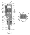
- FIG. 1 illustrates a longitudinal cross-section view of an injector according to a first embodiment of the invention
- FIG. 2 illustrates a cross-section view along the cross-section plane A-A of the injector in FIG. 1 ;
- FIG. 3 illustrates a longitudinal cross-section view of an injector according to a second embodiment of the invention
- FIG. 4 illustrates a longitudinal cross-section view of an injector according to a third embodiment of the invention
- FIG. 5 illustrates a longitudinal cross-section view of an injector according to a fourth embodiment of the invention.
- FIG. 6 illustrates a longitudinal cross-section view of an injector according to the prior art.
- a first embodiment of the injector 44 according to the invention is illustrated in longitudinal cross section in FIG. 1 .
- the injector 44 includes means of immobilizing the weight 28 in relation to the body 12 which are selectively activatable.
- These means of immobilizing include a piston 46 mounted such that it is free to move translationally in relation to the body 12 of the injector 44 along an axis x-x′ generally perpendicular to the axis y-y′ of the pin 24 .
- the means of immobilizing also include a bearing part 48 which can cooperate with the piston 46 so as to stop translation of the weight 28 along the axis y-y′.
- the piston 46 and/or the bearing part 48 has/have a face for bearing on the weight 28 having a shape which is complementary to that of the weight 28 .
- the weight 28 being, in this case, cylindrical
- the piston 46 and the bearing part 48 have a bearing face which can cooperate with the weight 28 of concave, generally cylindrical, shape.
- the immobilizing force exerted by the means of immobilizing is optimized for a given pressure.
- the bearing part 48 is made of hard steel.
- the piston 46 and the bearing part 48 are generally of the same height as the weight 28 so as to provide the largest possible contact surface between the piston, the weight and the bearing part.
- the immobilizing force exerted by the means of immobilizing is optimized for a given pressure.
- the injector 44 has a hydraulic control chamber 50 .
- This hydraulic control chamber 50 is defined on the one hand by the body 12 of the injector 44 and, on the other hand, by the piston 46 .
- the hydraulic control chamber 50 has a fuel inlet hole 52 .
- a fuel bypass channel 53 is connected to this fuel inlet hole 52 .
- the bypass channel 53 is connected at the other end to the supply channel 54 of the injector 44 , preferably between the supply hole 20 and the first cavity 18 .
- the hydraulic control chamber 50 has moreover a hydraulic fluid outlet hole 56 of which the cross section is, preferably, larger than the cross section of the inlet hole 52 .
- This outlet hole 56 is connected to the second cavity 34 .
- the second cavity 34 is closed by a plug 58 .
- This plug 58 has a low pressure fuel discharge channel 60 .
- the injector 44 includes a valve 62 , in this case of the electrical control type, preferably of the magnetostrictive, electromagnetic or electrostrictive type. This valve 62 can cut off the passage of fluid between the hydraulic control chamber 50 and the second cavity 34 .
- valve 62 When the valve 62 is not electrically fed, it is closed and the passage of fluid between the second cavity 34 and the hydraulic control chamber 50 is interrupted. The fuel is not therefore discharged toward the second cavity 34 . The pressure of the fuel in the hydraulic control chamber 50 therefore remains high, that is to say higher than the pressure of the fuel located in the second cavity 34 . That is why the fuel pushes the piston 46 along the axis x-x′ in the direction of the weight 28 . Thus, the piston 46 holds the weight 28 in its initial position by pressing the weight 28 against the bearing part 48 . This initial position of the weight 28 and the initial tension in the pin 24 are obtained by construction, in particular by means of the spring 30 disposed in the second cavity 34 .
- valve 62 When the valve 62 is electrically fed, it opens. The fuel is then discharged toward the second cavity 34 . The pressure in the hydraulic control chamber 50 then drops and the piston 46 relaxes its hold. The weight 28 is released and the tension in the pin 24 resumes the value that the spring 30 imparts to it.
- This activation of the opening of the valve 62 occurs at regular intervals (for example every minute) and for very short times, of the order of a few hundred milliseconds, in order to enable the tension in the pin 24 to resume the value imparted by the spring 30 , and eliminate excess tension which can occur in the pin 24 due to differential expansions of the body 12 of the injector 44 and the pin 24 .
- the opening of this valve 62 can, for example, be carried out between two successive injections.
- the fuel which is always supplied under pressure by a pump, continues to exert a pressure on the piston 46 . Therefore, in spite of the opening of the valve 62 , the fuel can tend to maintain a pressure, in the hydraulic control chamber 50 , higher than the pressure in the second cavity 34 .
- This problem is solved by the fact that the arrival of the fuel in the hydraulic control chamber 50 takes place via a narrow bypass channel 53 , and that the discharging of the fuel from the hydraulic control chamber 50 is carried out by means of a discharge hole 56 and a discharge channel 60 of larger diameter than the diameter of the bypass channel 53 .
- the pressure drop when discharging the fuel from the control chamber 50 is less than the pressure drop when filling this control chamber 50 . It is thus possible to facilitate the discharging of the fuel from the control chamber 50 so as to reduce, very rapidly, the pressure of the fuel in the control chamber 50 .
- the valve 62 preferably gives a small pressure drop in order that the pressure in the hydraulic control chamber 48 drops rapidly.
- the bypass channel 53 adequately prevents the pressure rise in the hydraulic control chamber 50 from rising again. Thus, the pressure of the fuel in the hydraulic control chamber 50 does not have time to rise to prevent the release of the weight 28 .
- valve 62 When the valve 62 is no longer fed, it closes so as to stop the passage of fluid between the hydraulic control chamber 50 and the second cavity 34 . The pressure in the hydraulic control chamber 50 then increases. The piston 46 is then pressed on the weight 28 against the bearing part 48 so as to immobilize the weight 28 , as illustrated in FIG. 2 . Immediately after immobilization, the force in the pin 24 has the value that the spring 30 imparts, the pin 24 being relieved of additional forces which could have been created as a result of differential expansions.
- FIG. 3 shows a second embodiment of the injector according to the invention.
- the injector 66 illustrated in FIG. 3 is different from the injector 44 according to the first embodiment of the invention in that it is an injector of the inward-opening valve type.
- the pin 24 is pressed, at rest, on the inner face of the lower end 22 of the nozzle 16 due to the action of the spring 30 which is mounted in the second cavity 34 .
- FIG. 4 shows a third embodiment of the injector according to the invention.
- the injector 70 illustrated in FIG. 4 is different from the injector 44 according to the first embodiment in that it does not have a stack 36 of active components, for example piezoelectric or magnetostrictive components, mounted on the body of the injector.
- a stack 72 of active components which can deform due to the action of an electric or magnetic field, preferably piezoelectric or magnetostrictive components, is solidly mounted on the pin 24 so that the deformation of this stack 72 of active components directly causes the setting in longitudinal vibration of the pin 24 .
- FIG. 5 shows a fourth embodiment of the injector according to the invention.
- the injector 74 illustrated in FIG. 5 is different from the injector 66 according to the second embodiment in that it does not have a stack 36 of active components, for example piezoelectric or magnetostrictive components, mounted on the body of the injector.
- a stack 72 of active components which can deform due to the action of an electric current, for example piezoelectric or magnetostrictive elements, is solidly mounted on the pin 24 so that the deformation of this stack 72 of active components directly causes the setting in longitudinal vibration of the pin 24 .
- the immobilizing piston and the bearing part can cooperate directly with the pin, the weight then possibly being able to be omitted.
- the device formed of the piston 46 and bearing part 48 is an advantageous embodiment of selectively activatable means of immobilizing, these elements can be replaced by any selectively activatable device effectively able to carry out the immobilizing of the weight and/or the pin.
- an electric or hydraulic actuator or a system of immobilizing by an electromagnet can be mentioned.
Landscapes
- Engineering & Computer Science (AREA)
- Chemical & Material Sciences (AREA)
- Combustion & Propulsion (AREA)
- Mechanical Engineering (AREA)
- General Engineering & Computer Science (AREA)
- Fuel-Injection Apparatus (AREA)
Applications Claiming Priority (3)
| Application Number | Priority Date | Filing Date | Title |
|---|---|---|---|
| FR0512894 | 2005-12-19 | ||
| FR0512894A FR2895031B1 (fr) | 2005-12-19 | 2005-12-19 | Injecteur de carburant pour moteur a combustion interne |
| PCT/FR2006/051247 WO2007071863A1 (fr) | 2005-12-19 | 2006-11-29 | Injecteur de carburant pour moteur a combustion interne |
Publications (2)
| Publication Number | Publication Date |
|---|---|
| US20090014554A1 US20090014554A1 (en) | 2009-01-15 |
| US8038080B2 true US8038080B2 (en) | 2011-10-18 |
Family
ID=36968668
Family Applications (1)
| Application Number | Title | Priority Date | Filing Date |
|---|---|---|---|
| US12/097,310 Expired - Fee Related US8038080B2 (en) | 2005-12-19 | 2006-11-29 | Fuel injector for an internal combustion engine |
Country Status (7)
| Country | Link |
|---|---|
| US (1) | US8038080B2 (de) |
| EP (1) | EP1963665B1 (de) |
| JP (1) | JP2009520153A (de) |
| AT (1) | ATE507391T1 (de) |
| DE (1) | DE602006021621D1 (de) |
| FR (1) | FR2895031B1 (de) |
| WO (1) | WO2007071863A1 (de) |
Cited By (3)
| Publication number | Priority date | Publication date | Assignee | Title |
|---|---|---|---|---|
| WO2014070516A1 (en) * | 2012-10-31 | 2014-05-08 | Tenneco Automotive Operating Company Inc. | Injector with capillary aerosol generator |
| US8978364B2 (en) | 2012-05-07 | 2015-03-17 | Tenneco Automotive Operating Company Inc. | Reagent injector |
| US9759113B2 (en) | 2012-05-10 | 2017-09-12 | Tenneco Automotive Operating Company Inc. | Coaxial flow injector |
Families Citing this family (14)
| Publication number | Priority date | Publication date | Assignee | Title |
|---|---|---|---|---|
| FR2914024A1 (fr) * | 2007-03-23 | 2008-09-26 | Renault Sas | Injecteur de carburant pour moteur a combustion interne |
| FR2918123A1 (fr) * | 2007-06-27 | 2009-01-02 | Renault Sas | Dispositif d'injection de fluide. |
| FR2922289A1 (fr) * | 2007-10-16 | 2009-04-17 | Renault Sas | Dispositif d'injection de fluide |
| DE102008000760A1 (de) * | 2008-03-19 | 2009-09-24 | Robert Bosch Gmbh | Bauelementpaarung sowie Vorrichtung mit Bauelementpaarung |
| FR2929656A1 (fr) * | 2008-04-03 | 2009-10-09 | Renault Sas | Injecteur de fluide, et procede de commande d'un tel injecteur |
| FR2936024B1 (fr) * | 2008-09-16 | 2014-08-08 | Renault Sas | Dispositif d'injection de fluide. |
| FR2936025A1 (fr) * | 2008-09-16 | 2010-03-19 | Renault Sas | Dispositif d'injection de fuide. |
| JP5695050B2 (ja) * | 2009-08-27 | 2015-04-01 | マクアリスター テクノロジーズ エルエルシー | 一体化された燃料噴射器及び点火器並びに関連する使用及び製造方法 |
| US20130068200A1 (en) * | 2011-09-15 | 2013-03-21 | Paul Reynolds | Injector Valve with Miniscule Actuator Displacement |
| US9562500B2 (en) | 2013-03-15 | 2017-02-07 | Mcalister Technologies, Llc | Injector-igniter with fuel characterization |
| US10297567B2 (en) * | 2015-12-18 | 2019-05-21 | Intel Corporation | Thermocompression bonding using plasma gas |
| CN109759255B (zh) * | 2019-03-05 | 2024-08-23 | 深圳万苍科技有限公司 | 一种注射喷涂阀 |
| CN112431693B (zh) * | 2020-11-19 | 2021-11-30 | 北京航空航天大学 | 针栓式喷注器、火箭发动机及火箭 |
| CN112780443B (zh) * | 2021-03-02 | 2022-03-01 | 北京航空航天大学 | 一种压电陶瓷微动针栓喷注器调节机构 |
Citations (5)
| Publication number | Priority date | Publication date | Assignee | Title |
|---|---|---|---|---|
| FR2738294A1 (fr) | 1995-08-29 | 1997-03-07 | Bosch Gmbh Robert | Injecteur pour moteur a combustion interne |
| FR2801346A1 (fr) | 1999-11-19 | 2001-05-25 | Renault | Dispositif d'injection de carburant pour moteur a combustion interne |
| US6474565B1 (en) * | 1999-07-14 | 2002-11-05 | Robert Bosch Gmbh | Fuel injection valve |
| EP1277941A2 (de) | 2001-07-21 | 2003-01-22 | Robert Bosch Gmbh | Verfahren zum Betreiben einer Brennkraftmaschine, insbesondere mit Direkteinspritzung, sowie Computerprogramm und Steuer- und/oder Regelgerät |
| US6543700B2 (en) * | 2000-12-11 | 2003-04-08 | Kimberly-Clark Worldwide, Inc. | Ultrasonic unitized fuel injector with ceramic valve body |
-
2005
- 2005-12-19 FR FR0512894A patent/FR2895031B1/fr not_active Expired - Fee Related
-
2006
- 2006-11-29 JP JP2008546536A patent/JP2009520153A/ja not_active Ceased
- 2006-11-29 AT AT06842058T patent/ATE507391T1/de not_active IP Right Cessation
- 2006-11-29 WO PCT/FR2006/051247 patent/WO2007071863A1/fr not_active Ceased
- 2006-11-29 EP EP06842058A patent/EP1963665B1/de not_active Ceased
- 2006-11-29 DE DE602006021621T patent/DE602006021621D1/de active Active
- 2006-11-29 US US12/097,310 patent/US8038080B2/en not_active Expired - Fee Related
Patent Citations (6)
| Publication number | Priority date | Publication date | Assignee | Title |
|---|---|---|---|---|
| FR2738294A1 (fr) | 1995-08-29 | 1997-03-07 | Bosch Gmbh Robert | Injecteur pour moteur a combustion interne |
| US5810255A (en) * | 1995-08-29 | 1998-09-22 | Robert Bosch Gmbh | Clamping device for a piesoelectric actuator of a fuel injection valve for internal combustion engines |
| US6474565B1 (en) * | 1999-07-14 | 2002-11-05 | Robert Bosch Gmbh | Fuel injection valve |
| FR2801346A1 (fr) | 1999-11-19 | 2001-05-25 | Renault | Dispositif d'injection de carburant pour moteur a combustion interne |
| US6543700B2 (en) * | 2000-12-11 | 2003-04-08 | Kimberly-Clark Worldwide, Inc. | Ultrasonic unitized fuel injector with ceramic valve body |
| EP1277941A2 (de) | 2001-07-21 | 2003-01-22 | Robert Bosch Gmbh | Verfahren zum Betreiben einer Brennkraftmaschine, insbesondere mit Direkteinspritzung, sowie Computerprogramm und Steuer- und/oder Regelgerät |
Non-Patent Citations (2)
| Title |
|---|
| U.S. Appl. No. 11/996,454, filed Apr. 22, 2008, Malek, et al. |
| U.S. Appl. No. 12/666,312, filed Dec. 23, 2009, Agneray, et al. |
Cited By (5)
| Publication number | Priority date | Publication date | Assignee | Title |
|---|---|---|---|---|
| US8978364B2 (en) | 2012-05-07 | 2015-03-17 | Tenneco Automotive Operating Company Inc. | Reagent injector |
| US10465582B2 (en) | 2012-05-07 | 2019-11-05 | Tenneco Automotive Operating Company Inc. | Reagent injector |
| US9759113B2 (en) | 2012-05-10 | 2017-09-12 | Tenneco Automotive Operating Company Inc. | Coaxial flow injector |
| WO2014070516A1 (en) * | 2012-10-31 | 2014-05-08 | Tenneco Automotive Operating Company Inc. | Injector with capillary aerosol generator |
| CN104769243A (zh) * | 2012-10-31 | 2015-07-08 | 天纳克汽车经营有限公司 | 具有毛细管气溶胶发生器的喷射器 |
Also Published As
| Publication number | Publication date |
|---|---|
| WO2007071863A1 (fr) | 2007-06-28 |
| ATE507391T1 (de) | 2011-05-15 |
| DE602006021621D1 (de) | 2011-06-09 |
| JP2009520153A (ja) | 2009-05-21 |
| EP1963665B1 (de) | 2011-04-27 |
| US20090014554A1 (en) | 2009-01-15 |
| EP1963665A1 (de) | 2008-09-03 |
| FR2895031B1 (fr) | 2011-06-03 |
| FR2895031A1 (fr) | 2007-06-22 |
Similar Documents
| Publication | Publication Date | Title |
|---|---|---|
| US8038080B2 (en) | Fuel injector for an internal combustion engine | |
| KR101519677B1 (ko) | 초음파 액체 전달 장치 | |
| KR101343695B1 (ko) | 초음파 연료 분사기 | |
| CN101910610B (zh) | 用于超声波液体传送装置的工作的控制系统和方法 | |
| KR101479366B1 (ko) | 초음파 액체 전달 장치 작동 방법 및 제어 시스템 | |
| KR101379065B1 (ko) | 초음파 연료 분사기 | |
| KR101351171B1 (ko) | 초음파 연료 분사기 | |
| US7669783B2 (en) | Metering valve with a hydraulic transmission element | |
| US20080210773A1 (en) | Fuel Injection Device for Internal Combustion Engine | |
| SE445244B (sv) | Ultraljudsinjektor for dieselmotor | |
| US6729554B2 (en) | Structure of fuel injector for avoiding injection of excess quantity of fuel | |
| CN103649519A (zh) | 压电式喷油器 | |
| CN103201498A (zh) | 燃料喷射器 | |
| US20090057438A1 (en) | Ultrasonically activated fuel injector needle | |
| US7784708B2 (en) | Fuel injecting device and method for controlling said device | |
| KR20110059643A (ko) | 유체 분사 장치 | |
| JP5462943B2 (ja) | 燃料噴射器 | |
| US20070001027A1 (en) | Fuel injector valve | |
| JP2004076733A (ja) | 内燃機関に用いられる燃料噴射弁 | |
| JP2753712B2 (ja) | エンジンの高圧燃料噴射装置 | |
| JP2011047292A (ja) | 燃料噴射装置 | |
| MX2008009428A (en) | Ultrasonic fuel injector | |
| JP2004351347A (ja) | 液体噴射装置 |
Legal Events
| Date | Code | Title | Description |
|---|---|---|---|
| AS | Assignment |
Owner name: RENAULT S.A.S., FRANCE Free format text: ASSIGNMENT OF ASSIGNORS INTEREST;ASSIGNORS:MALEK, NADIM;AGNERAY, ANDRE;REEL/FRAME:021564/0219 Effective date: 20080725 |
|
| FEPP | Fee payment procedure |
Free format text: PAYOR NUMBER ASSIGNED (ORIGINAL EVENT CODE: ASPN); ENTITY STATUS OF PATENT OWNER: LARGE ENTITY |
|
| REMI | Maintenance fee reminder mailed | ||
| LAPS | Lapse for failure to pay maintenance fees | ||
| STCH | Information on status: patent discontinuation |
Free format text: PATENT EXPIRED DUE TO NONPAYMENT OF MAINTENANCE FEES UNDER 37 CFR 1.362 |
|
| STCH | Information on status: patent discontinuation |
Free format text: PATENT EXPIRED DUE TO NONPAYMENT OF MAINTENANCE FEES UNDER 37 CFR 1.362 |
|
| FP | Lapsed due to failure to pay maintenance fee |
Effective date: 20151018 |