US8041040B2 - Sound image control apparatus and sound image control method - Google Patents
Sound image control apparatus and sound image control method Download PDFInfo
- Publication number
- US8041040B2 US8041040B2 US11/756,082 US75608207A US8041040B2 US 8041040 B2 US8041040 B2 US 8041040B2 US 75608207 A US75608207 A US 75608207A US 8041040 B2 US8041040 B2 US 8041040B2
- Authority
- US
- United States
- Prior art keywords
- sound
- sound image
- gain
- distance
- virtual
- Prior art date
- Legal status (The legal status is an assumption and is not a legal conclusion. Google has not performed a legal analysis and makes no representation as to the accuracy of the status listed.)
- Expired - Fee Related, expires
Links
- 230000005236 sound signal Effects 0.000 claims abstract description 120
- 230000004807 localization Effects 0.000 claims abstract description 104
- 238000000034 method Methods 0.000 claims abstract description 13
- 238000004091 panning Methods 0.000 claims description 107
- 230000005540 biological transmission Effects 0.000 abstract description 48
- 238000010586 diagram Methods 0.000 description 5
- 230000000694 effects Effects 0.000 description 2
- 230000001419 dependent effect Effects 0.000 description 1
- 230000035945 sensitivity Effects 0.000 description 1
Images


Classifications
-
- H—ELECTRICITY
- H04—ELECTRIC COMMUNICATION TECHNIQUE
- H04S—STEREOPHONIC SYSTEMS
- H04S3/00—Systems employing more than two channels, e.g. quadraphonic
-
- H—ELECTRICITY
- H04—ELECTRIC COMMUNICATION TECHNIQUE
- H04S—STEREOPHONIC SYSTEMS
- H04S5/00—Pseudo-stereo systems, e.g. in which additional channel signals are derived from monophonic signals by means of phase shifting, time delay or reverberation
-
- H—ELECTRICITY
- H04—ELECTRIC COMMUNICATION TECHNIQUE
- H04S—STEREOPHONIC SYSTEMS
- H04S7/00—Indicating arrangements; Control arrangements, e.g. balance control
- H04S7/30—Control circuits for electronic adaptation of the sound field
-
- H—ELECTRICITY
- H04—ELECTRIC COMMUNICATION TECHNIQUE
- H04S—STEREOPHONIC SYSTEMS
- H04S1/00—Two-channel systems
- H04S1/002—Non-adaptive circuits, e.g. manually adjustable or static, for enhancing the sound image or the spatial distribution
-
- H—ELECTRICITY
- H04—ELECTRIC COMMUNICATION TECHNIQUE
- H04S—STEREOPHONIC SYSTEMS
- H04S2400/00—Details of stereophonic systems covered by H04S but not provided for in its groups
- H04S2400/11—Positioning of individual sound objects, e.g. moving airplane, within a sound field
-
- H—ELECTRICITY
- H04—ELECTRIC COMMUNICATION TECHNIQUE
- H04S—STEREOPHONIC SYSTEMS
- H04S2400/00—Details of stereophonic systems covered by H04S but not provided for in its groups
- H04S2400/13—Aspects of volume control, not necessarily automatic, in stereophonic sound systems
Definitions
- the present invention relates to a sound image control apparatus and sound image control method for reproducing a transmission characteristic using a digital filter and convolving the transmission characteristic in an original sound (hereinafter, referred to as a source sound), and thereby controlling sound image localization.
- a sound image control apparatus which uses a fact that the transmission characteristic changes due to influence of the shape of head and auricles according to the direction of a sound source position when a human catches a sound, reproduces a transmission characteristic using a digital filter and convolves the transmission characteristic in a source sound, and thereby controls sound image localization.
- Patent Document 1 Japanese Patent Application Laid-Open No. H07-298399 discloses a stereophonic sound listening device holding transmission filters at intervals corresponding to a sound discrimination limit of a human when sound wave transmission characteristics of arrival sounds in respective directions around a head of a listener are reproduced.
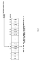
- FIG. 1 is a block diagram illustrating a configuration of a conventional sound image control apparatus.
- sound image control apparatus 10 is configured with sound image control section 11 , virtual sound field 1 sound image localization section 12 , virtual sound field 2 sound image localization section 13 , Panning Gain control section 14 , virtual reflected sound generating section 15 and localized sound/virtual reflected sound adding section 16 .
- Panning Gain control section 14 is configured with virtual sound field 1 Rch Panning Gain control section 21 , virtual sound field 1 Lch Panning Gain control section 22 , virtual sound field 2 Rch Panning Gain control section 23 , and virtual sound field 2 Lch Panning Gain control section 24 , and localized sound/virtual reflected sound adding section 16 is configured with Rch localized sound/virtual reflected sound adder 25 and Lch localized sound/virtual reflected sound adder 26 .
- Virtual sound field 1 sound image localization section 12 and virtual sound field 2 sound image localization section 13 control localization to be in an arbitrary position mainly using a transmission characteristic filter (data).
- Panning Gain control section 14 performs cross-fade processing on audio signals outputted from virtual sound field 1 sound image localization section 12 and virtual sound field 2 sound image localization section 13 .
- Sound image control apparatus 10 receives monaural input audio signal 30 as input, and outputs Rch output audio signal 31 and Lch output audio signal 32 . Further, “ 41 ” is a transmission characteristic filter transfer system to virtual sound field 1 sound image localization section 12 , and “ 42 ” is a transmission characteristic filter transfer system to virtual sound field 2 sound image localization section 13 .
- Sound image control section 11 outputs virtual sound field 1 Panning Gain control section control signal 43 to virtual sound field 1 Rch Panning Gain control section 21 and virtual sound field 1 Lch Panning Gain control section 22 , and further outputs virtual sound field 2 Panning Gain control section control signal 44 to virtual sound field 2 Rch Panning Gain control section 23 and virtual sound field 2 Lch Panning Gain control section 24 .
- Virtual sound field 1 Rch Panning Gain control section 21 , virtual sound field 1 Lch Panning Gain control section 22 , virtual sound field 2 Rch Panning Gain control section 23 and virtual sound field 2 Lch Panning Gain control section 24 are controlled in gain by virtual sound field 1 Panning Gain control section control signal 43 and virtual sound field 2 Panning Gain control section control signal 44 , and respectively output virtual sound field 1 Rch Panning Gain control section audio signal 45 , virtual sound field 1 Lch Panning Gain control section audio signal 46 , virtual sound field 2 Rch Panning Gain control section audio signal 47 and virtual sound field 2 Lch Panning Gain control section audio signal 48 to Rch localized sound/virtual reflected sound adder 25 and Lch localized sound/virtual reflected sound adder 26 .
- virtual reflected sound generating section 15 outputs virtual reflected sound generating section Rch output audio signal 49 and virtual reflected sound generating section Lch output audio signal 50 to Rch localized sound/virtual reflected sound adder 25 and Lch localized sound/virtual reflected sound adder 26 , respectively.
- Rch localized sound/virtual reflected sound adder 25 adds virtual sound field 1 Rch Panning Gain control section audio signal 45 , virtual sound field 2 Rch Panning Gain control section audio signal 47 and virtual reflected sound generating section Rch output audio signal 49 , and outputs the result as Rch output audio signal 31 .
- Lch localized sound/virtual reflected sound adder 26 adds virtual sound field 1 Lch Panning Gain control section audio signal 46 , virtual sound field 2 Lch Panning Gain control section audio signal 48 and virtual reflected sound generating section Lch output audio signal 50 , and outputs the result as Lch output audio signal 32 .
- Patent Document 1 intends to realize the sound image localization with higher accuracy without increasing the data amount so much by preparing the transmission characteristic filters at only intervals corresponding to the sound discrimination limit of a human.
- transmission characteristic filters for the distance direction, it is necessary to prepare transmission characteristic filters in all directions for each distance, and therefore, in order to increase the accuracy in the distance direction, transmission characteristic filters corresponding to all directions are required for one distance and there is a problem that an enormous amount of transmission characteristic filters are required.
- a sound image control apparatus adopts a configuration including: a distance gain control section that performs gain control of a sound pressure of a monaural audio input signal of one channel with respect to a distance direction from a head to a sound image; a sound image localization section that performs sound image localization operation of an elevation angle and azimuth on the audio signal subjected to distance gain control based on parameter data corresponding to a position in which the sound image is localized; a Panning Gain control section that performs cross-fade processing on stereo audio signals of two channels outputted from the sound image localization section and controls the sound pressure; a localized sound/virtual reflected sound adding section that adds an audio signal including localization information outputted from the Panning Gain control section to the stereo audio signals of two channels, respectively, and outputs stereo audio output signals of two channels; and a sound image control section that sets the parameter data and gain values for gain control to the sound image localization section, the distance gain control section and the Panning Gain control section.
- a sound image control apparatus adopts a configuration including: a distance gain control section that performs gain control of a sound pressure of a monaural audio input signal of one channel with respect to a distance direction from a head to a sound image; a sound image localization section that performs sound image localization operation of an elevation angle and azimuth on the audio signal subjected to distance gain control based on parameter data corresponding to a position in which the sound image is localized; a reflected sound gain control section that performs gain control by distance of a reflected sound of the sound pressure of the monaural audio input signal of one channel; a virtual reflected sound generating section that generates a virtual reflected sound and localizes the sound image outside a head when the sound is listened to with headphones, for the audio signal subjected to reflected sound gain control; a Panning Gain control section that performs cross-fade processing on stereo audio signals of two channels outputted from the sound image localization section and controls the sound pressure; a localized sound/vir
- a sound image control method includes: a distance gain step of performing gain control of a sound pressure of a monaural audio input signal of one channel with respect to a distance direction from a head to a sound image; a first sound image localization step of performing sound image localization operation on the audio signal subjected to distance gain control based on first parameter data corresponding to a position in which the sound image is localized; a second sound image localization step of performing sound image localization operation on the audio signal subjected to distance gain control based on second parameter data corresponding to the position in which the sound image is localized; a reflected sound gain step of performing gain control by distance of a reflected sound of the sound pressure of the monaural audio input signal of one channel; a virtual reflected sound generating step of generating a virtual reflected sound to localize the sound image outside a head when the sound is listened to with headphones, for the audio signal subjected to reflected sound gain control; a Panning Gain control step of performing cross-fade processing on
- FIG. 1 is a block diagram showing a configuration of a conventional sound image control apparatus
- FIG. 2 is a block diagram showing a configuration of a sound image control apparatus according to one embodiment of the present invention
- FIG. 3 shows an example of a Panning Gain table in the sound image control apparatus according to the above-described embodiment
- FIG. 4 shows actual values of a memory of the Panning Gain table in the sound image control apparatus according to the above-described embodiment
- FIG. 5 shows an example of a distance gain table in the sound image control apparatus according to the above-described embodiment
- FIG. 6 shows an example of a reflected sound gain table in the sound image control apparatus according to the above-described embodiment
- FIG. 7 shows actual values of a memory of the distance gain table in the sound image control apparatus according to the above-described embodiment.
- FIG. 8 illustrates move of a sound image in the sound image control apparatus according to the above-described embodiment.
- FIG. 2 is a block diagram showing a configuration of the sound image control apparatus according to one embodiment of the present invention. This embodiment describes an example where the present invention is applied to a sound image control apparatus that localizes a sound image in an arbitrary position around a listener using stereo audio signals of two channels.
- sound image control apparatus 100 is configured with distance gain control section 101 , reflected sound gain control section 102 , sound image control section 110 , virtual sound field 1 sound image localization section 120 , virtual sound field 2 sound image localization section 130 , Panning Gain control section 140 , virtual reflected sound generating section 150 and localized sound/virtual reflected sound adding section 160 .
- Panning Gain control section 140 is configured with virtual sound field 1 Rch Panning Gain control section 141 , virtual sound field 1 Lch Panning Gain control section 142 , virtual sound field 2 Rch Panning Gain control section 143 and virtual sound field 2 Lch Panning Gain control section 144 , and localized sound/virtual reflected sound adding section 160 is configured with Rch localized sound/virtual reflected sound adder 161 and Lch localized sound/virtual reflected sound adder 162 .
- Sound image control apparatus 100 receives monaural input audio signal 170 as input, and outputs Rch output audio signal 171 and Lch output audio signal 172 . Further, “ 181 ” is a transmission characteristic filter transfer system to virtual sound field 1 sound image localization section 120 , and “ 182 ” is a transmission characteristic filter transfer system to virtual sound field 2 sound image localization section 130 .
- Sound image control section 110 outputs distance gain control section control signal 191 to distance gain control section 101 , and reflected sound gain control section control signal 192 to reflected sound gain control section 102 . Further, sound image control section 110 outputs virtual sound field 1 Panning Gain control section control signal 183 to virtual sound field 1 Rch Panning Gain control section 141 , and virtual sound field 1 Lch Panning Gain control section 142 , while outputting virtual sound field 2 Panning Gain control section control signal 184 to virtual sound field 2 Rch Panning Gain control section 143 and virtual sound field 2 Lch Panning Gain control section 144 .
- Distance gain control section 101 outputs distance gain control section output audio signal 193 to virtual sound field 1 sound image localization section 120 , and virtual sound field 2 sound image localization section 130 , and reflected sound gain control section 102 outputs reflected sound gain control section output audio signal 194 to virtual reflected sound generating section 150 .
- Virtual sound field 1 Rch Panning Gain control section 141 , virtual sound field 1 Lch Panning Gain control section 142 , virtual sound field 2 Rch Panning Gain control section 143 and virtual sound field 2 Lch Panning Gain control section 144 are controlled in gain by virtual sound field 1 Panning Gain control section control signal 183 and virtual sound field 2 Panning Gain control section control signal 184 , and respectively output virtual sound field 1 Rch Panning Gain control section audio signal 185 , virtual sound field 1 Lch Panning Gain control section audio signal 186 , virtual sound field 2 Rch Panning Gain control section audio signal 187 and virtual sound field 2 Lch Panning Gain control section audio signal 188 to Rch localized sound/virtual reflected sound adder 161 and Lch localized sound/virtual reflected sound adder 162 .
- virtual reflected sound generating section 150 outputs virtual reflected sound generating section Rch output audio signal 189 and virtual reflected sound generating section Lch output audio signal 190 to Rch localized sound/virtual reflected sound adder 166 and Lch localized sound/virtual reflected sound adder 162 .
- Rch localized sound/virtual reflected sound adder 161 adds virtual sound field 1 Rch Panning Gain control section audio signal 185 , virtual sound field 2 Rch Panning Gain control section audio signal 187 and virtual reflected sound generating section Rch output audio signal 189 , and outputs the result as Rch output audio signal 171 .
- Lch localized sound/virtual reflected sound adder 162 adds virtual sound field 1 Lch Panning Gain control section audio signal 186 , virtual sound field 2 Lch Panning Gain control section audio signal 188 and virtual reflected sound generating section Lch output audio signal 190 , and outputs the result as Lch output audio signal 172 .
- Distance gain control section 101 performs gain control of a sound pressure of an inputted monaural audio signal of one channel for a distance direction from a head to a sound image, and outputs distance gain control section output audio signal 193 subjected to distance gain control to virtual sound field 1 sound image localization section 120 and virtual sound field 2 sound image localization section 130 .
- Reflected sound gain control section 102 performs gain control by distance of a reflected sound of the sound pressure of the inputted monaural audio signal of one channel, and outputs reflected sound gain control section output audio signal 194 subjected to reflected sound gain control to virtual reflected sound generating section 150 .
- Sound image control section 110 sets first parameter data for localizing a sound image in a given position to virtual sound field 1 sound image localization section 120 , sets second parameter data for localizing a sound image in a position that is the same or different as/from the given position to virtual sound field 2 sound image localization section 130 , and sets predetermined gain values to distance gain control section 101 , Panning Gain control section 140 and reflected sound gain control section 102 .
- sound image control section 110 has distance gain table 210 (see FIGS. 5 and 7 ) to refer to a gain value set at a given distance upon changing the sound pressure according to the distance, reflected sound gain table 220 (see FIGS. 6 and 7 ) to refer to a gain value set at a given distance upon changing the sound pressure according to the distance, and Panning Gain table 200 (see FIGS. 3 and 4 ) to refer to a gain value set at a given move time upon changing the sound pressure according to the move time, and sets gain characteristics in accordance with characteristics of a virtual sound field to distance gain table 210 , reflected sound gain table 220 and Panning Gain table 200 .
- Sound image control section 110 sets the move time upon move from a starting point to an endpoint and distances to the starting point and the endpoint, refers to distance gain table 210 , reflected sound gain table 220 and Panning Gain table 200 , and thereby automatically sets, for each unit of time, gain values corresponding to the move elapsed time and the move distance at the time, to distance gain control section 101 , reflected sound gain control section 102 and Panning Gain control section 140 .
- Virtual sound field 1 sound image localization section 120 and virtual sound field 2 sound image localization section 130 are sound image localization sections for localizing a sound image in an arbitrary position around a listener using stereo audio signals of two channels, set parameter data corresponding to the position in which the sound image is localized, and based on the set parameter data, perform sound image localization operation of an elevation angle and azimuth on the inputted monaural audio signal of one channel.
- Panning Gain control section 140 performs cross-fade processing on audio signals outputted from virtual sound field 1 sound image localization section 120 and virtual sound field 2 sound image localization section 130 , and controls sound pressures of stereo audio signals of two channels outputted from virtual sound field 1 sound image localization section 120 and virtual sound field 2 sound image localization section 130 .
- Virtual reflected sound generating section 150 generates a virtual reflected sound for localizing a sound image outside the head when the sound is listened to with headphones.
- sound image control apparatus 100 has distance gain control section 101 that performs gain control in the distance direction, before input to virtual sound field 1 sound image localization section 120 and virtual sound field 2 sound image localization section 130 that control the elevation angle and azimuth through transmission characteristic filter processing, and also has reflected sound gain control section 102 that performs gain control by distance of a reflected sound, before input to virtual reflected sound generating section 150 for controlling the sound image to be localized outside the head when the sound is listened to with headphones, and thereby performs gain control relating to the distance independently of the transmission characteristic filter processing.
- FIG. 3 shows an example of above-described Panning Gain table 200 .
- the horizontal axis indicates index [index] which is a reference address, and the vertical axis indicates gain [dB].
- Panning Gain table 200 has two table values: Fade Out table value (see sign ⁇ ) and Fade In table value (see sign ⁇ ) for performing the cross-fade processing of an audio signal. Sign points in the figure indicate values actually held in the table.
- FIG. 4 shows actual values (gain values) of a memory of Panning Gain table 200 of FIG. 3 .
- Panning Gain table 200 stores Fade Out and Fade In table values corresponding to reference addresses 0 - 127 [address].
- the reference operation of Panning Gain table 200 is as described below.
- Sound image control section 110 calculates a reference address from the move time, reads out values (gain values) of the memory of the corresponding reference address by referring to Panning Gain table 200 of FIG. 4 , and sets the read out gain values to Panning Gain control section 140 .
- sound image control section 110 reads out Fade In gain value “ ⁇ 1.981” and Fade Out gain value “ ⁇ 13.811” corresponding to reference address “ 26 ” and sets the values to Panning Gain control section 140 .
- the cross-fade processing of an audio signal using the Panning Gain table as described above is performed at Panning Gain control section 14 as shown in FIG. 1 .
- FIG. 5 shows an example of above-described distance gain table 210 .
- the horizontal axis indicates a distance [cm] from the head, and the vertical axis indicates gain [dB].
- Distance gain table 210 has two table values; SP gain value (see sign ⁇ ) and HP gain value (see sign ⁇ )
- distance gain table 210 has two gain values, but may have three or more values for changing the sensitivity according to specifications. Sign points in the figure indicate values actually held in the table.
- a change amount of gain changes largely in accordance with the distance (the change amount is larger when the distance is short), and therefore three regions are provided according to the distance, and by changing the interval of stored table values for each of three regions, the capacity of the gain table is reduced.
- the table values are stored at intervals of 1 cm in region a. where the change amount is the largest with respect to the distance, at intervals of 8 cm in region b. where the change amount is the second largest with respect to the distance, and at intervals of 16 cm in region c. where the change amount is small with respect to the distance.
- FIG. 6 shows an example of above-described reflected sound gain table 220 .
- the horizontal axis indicates a distance [cm] from a head, and the vertical axis indicates gain [dB].
- Sign points (see sign ⁇ ) in the figure indicate values actually held in the table.
- the change amount of gain changes largely in accordance with the distance (the change amount is large when the distance is short) also in reflected sound gain table 220 , three regions are provided according to the distance, and by changing the interval of the stored table values for each of three regions, the capacity of the gain table is reduced.
- the table values are stored at intervals of 1 cm in region a. where the change amount is the largest with respect to the distance, at intervals of 8 cm in region b. where the change amount is the second largest with respect to the distance, and at intervals of 16 cm in region c. where the change amount is small with respect to the distance.
- FIG. 7 shows actual values (gain values) of the memory of distance gain table 210 of FIG. 5 .
- the case of HP gain value is adopted as an example, but it is the same for the cases of SP gain value and reflected sound gain value in reflected sound gain table 220 in FIG. 6 .
- distance gain table 210 stores table values corresponding to reference addresses 0 - 255 [address]. The reference operation for distance gain table 210 (that is the same as for reflected sound gain table 220 ) is as described below.
- Sound image control section 110 calculates a reference address from the distance, reads out a value (gain value) of the memory of the corresponding reference address by referring to above-described distance gain table 210 (reflected sound gain table 220 ), and sets the read out gain value to distance gain control section 101 (reflected sound gain control section 102 ). For example, when reference address “ 166 ” is calculated from the distance, sound image control section 110 reads out gain value “ ⁇ 11.204” corresponding to reference address “ 166 ” and sets the gain value to distance gain control section 101 (reflected sound gain control section 102 ).
- FIG. 8 illustrates move of a sound image
- point A of the sound image with an azimuthal angle (angle) and elevation angle (elevation) of (a 1 , e 1 ) exists ahead of head 300 on the left
- point B of the sound image with an azimuthal angle and elevation angle of (a 2 , e 2 ) exists ahead of head 300 on the right.
- the filter coefficients at point A and point B are respectively set to virtual sound field 1 sound image localization section 120 and virtual sound field 2 sound image localization section 130 .
- sound images indicating actual sound images are assumed to be A′ (a 1 , e 1 , d 1 ) and B′ (a 2 , e 2 , d 2 ).
- distance d 1 of point A′ and distance d 2 of point B′ which are distance information indicating the distance from head 300 are newly added.
- Distance gain control section 101 refers to distance gain table 210 to control distance d 1 of point A′ and distance d 2 of point B′ independently of the azimuthal angle and elevation angle, and thereby can control a move of the sound image from point A′ to point B′.
- the filter coefficients do not depend on the distance, and therefore the distance of a size (about 10 to 15 cm) of head 300 is preferably used as a reference.
- the above-described filer coefficients are set to virtual sound field 1 sound image localization section 120 and virtual sound field 2 sound image localization section 130 , and as in the conventional example, control is performed on the elevation angle and azimuth through the transmission characteristic filter processing.
- distance gain control section 101 that performs gain control in the distance direction is provided before input to virtual sound field 1 sound image localization section 120 and virtual sound field 2 sound image localization section 130 , and, first, virtual sound field 1 sound image localization section 120 and virtual sound field 2 sound image localization section 130 perform sound image localization control through sound image localization operation on the monaural input audio signal of one channel subjected to gain control by distance gain control section 101 .
- reflected sound gain control section 102 that performs gain control by distance of a reflected sound is provided before input to virtual reflected sound generating section 150 , and the reflected sound is also subjected to gain control by distance as in the case of the above-described sound image localization.
- monaural input audio signal 170 of one channel is inputted to distance gain control section 101 and reflected sound gain control section 102 .
- distance gain control section 101 Upon receiving monaural input audio signal 170 of one channel, distance gain control section 101 refers to distance gain table 210 ( FIG. 5 ) internally stored in sound image control section 110 , and reads out a distance gain value corresponding to the distance information at the current moment. The operation for distance gain table 210 is as described in FIG. 7 . By distance gain control section 101 , it is possible to control the sound pressure of monaural input audio signal 170 to be the distance gain value, and perform control of the sound image in the distance direction.
- reflected sound gain control section 102 refers to reflected sound gain table 220 ( FIG. 6 ) internally stored in sound image control section 110 , and reads out a reflected sound gain value corresponding to the distance information at the current moment.
- reflected sound gain control section 102 By controlling the sound pressure of the virtual reflected sound according to the distance when the sound is listened to with headphones by reflected sound gain control section 102 , it is possible to control outside-head localization.
- Virtual sound field 1 sound image localization section 120 and virtual sound field 2 sound image localization section 130 perform sound image localization operation using transmission characteristic filters on the monaural input audio signal controlled to be the distance gain value by distance gain control section 101 , and localize a sound image in an arbitrary position around a listener.
- Panning Gain control section 140 refers to Panning Gain table 200 ( FIG. 3 ) internally stored in sound image control section 110 , and sets Panning Gain values corresponding to the Panning information at the current moment to virtual sound field 1 Rch Panning Gain control section 141 , virtual sound field 1 Lch Panning Gain control section 142 , virtual sound field 2 Rch Panning Gain control section 143 and virtual sound field 2 Lch Panning Gain control section 144 .
- virtual sound field 1 Rch Panning Gain control section 141 Based on the set Panning Gain values, virtual sound field 1 Rch Panning Gain control section 141 , virtual sound field 1 Lch Panning Gain control section 142 , virtual sound field 2 Rch Panning Gain control section 143 and virtual sound field 2 Lch Panning Gain control section 144 perform the cross-fade processing on the audio signal outputted from virtual sound field 1 sound image localization section 120 and virtual sound field 2 sound image localization section 130 .
- reflected sound gain control section 102 outputs to virtual reflected sound generating section 150 reflected sound gain control section output audio signal 194 controlled to be the sound pressure of the virtual reflected sound according to the distance when the sound is listened to with headphones.
- virtual reflected sound generating section 150 Based on reflected sound gain control section output audio signal 194 , virtual reflected sound generating section 150 generates a virtual reflected sound by an acoustic characteristic filter of a given space and controls outside-head localization when the sound is listened to with headphones.
- Rch localized sound/virtual reflected sound adder 161 and Lch localized sound/virtual reflected sound adder 162 of localized sound/virtual reflected sound adder 160 add the audio signal including localization information outputted from Panning Gain control section 140 and the audio signal of the virtual reflected sound outputted from virtual reflected sound generating section 150 in Rch and Lch, respectively and thereby output Rch output audio signal 171 and Lch output audio signal 172 .
- a sound image control step is executed as appropriate for setting first parameter data, second parameter data and gain values for gain control.
- sound image control apparatus 100 is provided with: distance gain control section 101 that performs gain control of the sound pressure of an inputted monaural audio signal of one channel for the distance direction from a head to a sound image before input to virtual sound field 1 sound image localization section 120 and virtual sound field 2 sound image localization section 130 ; and reflected sound gain control section 102 that performs gain control by distance of a reflected sound of the sound pressure of the inputted monaural audio signal of one channel before input to virtual reflected sound generating section 150 for controlling the sound image to be localized outside the head when the sound is listened to with headphones, so that it is possible to perform the gain control for the distance independently of the transmission characteristic filter processing.
- distance gain control section 101 first performs control in the distance direction by independent gain control, and then, sound image localization sections 120 and 130 perform sound image localization operation for localizing a sound image on the audio signal subjected to gain control in the distance.
- sound image localization sections 120 and 130 perform sound image localization operation for localizing a sound image on the audio signal subjected to gain control in the distance.
- reflected sound gain control section 102 first performs gain control by the distance on the reflected sound, and then, for the audio signal subjected to reflected sound gain control, virtual reflected sound generating section 150 controls the sound image to be localized outside the head.
- control in the distance direction can be performed by independent gain control, and therefore by holding transmission characteristic filters corresponding to elevation angles and azimuths at fixed intervals with respect to one distance, it is possible to implement the sound image localization image with high accuracy also in the distance direction.
- control in the distance direction can be performed by independent gain control, and therefore by holding transmission characteristic filters corresponding to elevation angles and azimuths at fixed intervals with respect to one distance, it is possible to implement the sound image localization image with high accuracy also in the distance direction.
- the present invention can be implemented with an apparatus not having reflected sound gain control section 102 and virtual reflected sound generating section 150 .
- this embodiment describes the example where the present invention is applied to a sound image control apparatus of audio signals, but the present invention can be applied to similar other sound image control apparatuses.
- FIGS. 3 to 8 are examples, and may be of data structure.
- this embodiment uses the title of the sound image control apparatus and sound image control method for convenience in description, but naturally, other titles are available such as a sound apparatus, sound reproducing system, sound image localization method and the like.
- circuit sections for example, signal processing sections, configuring the above-described sound image control apparatus, the number of channels, connection methods and the like are not limited to the embodiment as described above.
- the sound image control apparatus and sound image control method according to the present invention by enabling the gain control in sound image localization in the distance direction to be performed independently of the transmission characteristic filter processing, it is possible to increase the accuracy, in particular in the distance direction while keeping fixed intervals of transmission characteristic filters, without increasing the number of the transmission characteristic filters, and the sound image control apparatus and sound image control method are useful as a sound image control apparatus and the like of a mobile equipment and the like, and can be applied to use of a game apparatus and the like.
Landscapes
- Physics & Mathematics (AREA)
- Engineering & Computer Science (AREA)
- Acoustics & Sound (AREA)
- Signal Processing (AREA)
- Stereophonic System (AREA)
Applications Claiming Priority (2)
| Application Number | Priority Date | Filing Date | Title |
|---|---|---|---|
| JP2006164884A JP4914124B2 (ja) | 2006-06-14 | 2006-06-14 | 音像制御装置及び音像制御方法 |
| JP2006-164884 | 2006-06-14 |
Publications (2)
| Publication Number | Publication Date |
|---|---|
| US20070291949A1 US20070291949A1 (en) | 2007-12-20 |
| US8041040B2 true US8041040B2 (en) | 2011-10-18 |
Family
ID=38567001
Family Applications (1)
| Application Number | Title | Priority Date | Filing Date |
|---|---|---|---|
| US11/756,082 Expired - Fee Related US8041040B2 (en) | 2006-06-14 | 2007-05-31 | Sound image control apparatus and sound image control method |
Country Status (5)
| Country | Link |
|---|---|
| US (1) | US8041040B2 (fr) |
| EP (1) | EP1868416A3 (fr) |
| JP (1) | JP4914124B2 (fr) |
| KR (1) | KR20070119542A (fr) |
| CN (1) | CN101090585A (fr) |
Cited By (2)
| Publication number | Priority date | Publication date | Assignee | Title |
|---|---|---|---|---|
| US20100296657A1 (en) * | 2007-11-23 | 2010-11-25 | Chung Won Sup | Apparatus for sound having multiples stereo imaging |
| US9900735B2 (en) | 2015-12-18 | 2018-02-20 | Federal Signal Corporation | Communication systems |
Families Citing this family (17)
| Publication number | Priority date | Publication date | Assignee | Title |
|---|---|---|---|---|
| CN1889172A (zh) * | 2005-06-28 | 2007-01-03 | 松下电器产业株式会社 | 可增加和修正声音类别的声音分类系统及方法 |
| US8520873B2 (en) * | 2008-10-20 | 2013-08-27 | Jerry Mahabub | Audio spatialization and environment simulation |
| EP2108417B1 (fr) * | 2008-04-11 | 2018-07-18 | Sony Interactive Entertainment Inc. | Appareil audio et procédé |
| KR101040086B1 (ko) * | 2009-05-20 | 2011-06-09 | 전자부품연구원 | 오디오 생성방법, 오디오 생성장치, 오디오 재생방법 및 오디오 재생장치 |
| CA2740296C (fr) * | 2010-01-06 | 2018-05-01 | Skullcandy, Inc. | Casque d'ecoute de mixage pour dj |
| JP5672741B2 (ja) * | 2010-03-31 | 2015-02-18 | ソニー株式会社 | 信号処理装置および方法、並びにプログラム |
| KR20120004909A (ko) * | 2010-07-07 | 2012-01-13 | 삼성전자주식회사 | 입체 음향 재생 방법 및 장치 |
| JP5118267B2 (ja) | 2011-04-22 | 2013-01-16 | パナソニック株式会社 | 音声信号再生装置、音声信号再生方法 |
| KR101703333B1 (ko) * | 2013-03-29 | 2017-02-06 | 삼성전자주식회사 | 오디오 장치 및 이의 오디오 제공 방법 |
| KR20160122029A (ko) * | 2015-04-13 | 2016-10-21 | 삼성전자주식회사 | 스피커 정보에 기초하여, 오디오 신호를 처리하는 방법 및 장치 |
| KR102716952B1 (ko) * | 2017-03-28 | 2024-10-14 | 매직 립, 인코포레이티드 | 공간화된 오디오가 사용자 조작 가상 객체들에 결속된 증강 현실 시스템 |
| EP3454578B1 (fr) * | 2017-09-06 | 2020-11-04 | Sennheiser Communications A/S | Système de communication pour communication de signaux audio entre une pluralité de dispositifs de communication dans un environnement sonore virtuel |
| JP6785385B2 (ja) | 2018-03-07 | 2020-11-18 | マジック リープ, インコーポレイテッドMagic Leap,Inc. | 周辺デバイスの視覚的追跡 |
| WO2021121698A1 (fr) * | 2019-12-19 | 2021-06-24 | Telefonaktiebolaget Lm Ericsson (Publ) | Rendu audio de sources audio |
| JP7600526B2 (ja) * | 2020-02-19 | 2024-12-17 | ヤマハ株式会社 | 音信号処理方法および音信号処理装置 |
| CN114598984B (zh) * | 2022-01-11 | 2023-06-02 | 华为技术有限公司 | 立体声合成方法和系统 |
| WO2025263299A1 (fr) * | 2024-06-17 | 2025-12-26 | ソニーグループ株式会社 | Dispositif de traitement de signal et procédé de traitement de signal |
Citations (19)
| Publication number | Priority date | Publication date | Assignee | Title |
|---|---|---|---|---|
| US4817149A (en) * | 1987-01-22 | 1989-03-28 | American Natural Sound Company | Three-dimensional auditory display apparatus and method utilizing enhanced bionic emulation of human binaural sound localization |
| JPH0430700A (ja) | 1990-05-24 | 1992-02-03 | Roland Corp | 音像定位装置 |
| JPH0580755A (ja) | 1991-09-24 | 1993-04-02 | Yamaha Corp | 電子楽器 |
| JPH05300597A (ja) | 1992-04-18 | 1993-11-12 | Yamaha Corp | 映像連動音像定位装置 |
| JPH06282285A (ja) | 1993-03-29 | 1994-10-07 | Sanyo Electric Co Ltd | 立体音声再生装置 |
| US5386082A (en) * | 1990-05-08 | 1995-01-31 | Yamaha Corporation | Method of detecting localization of acoustic image and acoustic image localizing system |
| JPH07123498A (ja) | 1993-08-31 | 1995-05-12 | Victor Co Of Japan Ltd | ヘッドホン再生システム |
| JPH07298399A (ja) | 1994-04-28 | 1995-11-10 | Sharp Corp | 立体音響受聴装置 |
| US5581618A (en) | 1992-04-03 | 1996-12-03 | Yamaha Corporation | Sound-image position control apparatus |
| US5598478A (en) * | 1992-12-18 | 1997-01-28 | Victor Company Of Japan, Ltd. | Sound image localization control apparatus |
| US5715317A (en) | 1995-03-27 | 1998-02-03 | Sharp Kabushiki Kaisha | Apparatus for controlling localization of a sound image |
| US5742688A (en) * | 1994-02-04 | 1998-04-21 | Matsushita Electric Industrial Co., Ltd. | Sound field controller and control method |
| US6370256B1 (en) * | 1998-03-31 | 2002-04-09 | Lake Dsp Pty Limited | Time processed head related transfer functions in a headphone spatialization system |
| US20020172370A1 (en) * | 2001-05-15 | 2002-11-21 | Akitaka Ito | Surround sound field reproduction system and surround sound field reproduction method |
| US6763115B1 (en) | 1998-07-30 | 2004-07-13 | Openheart Ltd. | Processing method for localization of acoustic image for audio signals for the left and right ears |
| JP2005223646A (ja) | 2004-02-05 | 2005-08-18 | Nippon Hoso Kyokai <Nhk> | 音声調整卓 |
| US20050220308A1 (en) | 2004-03-31 | 2005-10-06 | Yamaha Corporation | Apparatus for creating sound image of moving sound source |
| US20060083394A1 (en) * | 2004-10-14 | 2006-04-20 | Mcgrath David S | Head related transfer functions for panned stereo audio content |
| JP4030700B2 (ja) | 1999-04-20 | 2008-01-09 | 花王株式会社 | 漂白活性化剤造粒物 |
Family Cites Families (3)
| Publication number | Priority date | Publication date | Assignee | Title |
|---|---|---|---|---|
| JPH07288899A (ja) * | 1994-04-15 | 1995-10-31 | Matsushita Electric Ind Co Ltd | 音場再生装置 |
| JPH11313398A (ja) * | 1998-04-28 | 1999-11-09 | Nippon Telegr & Teleph Corp <Ntt> | ヘッドホン装置並びにヘッドホン装置制御方法およびヘッドホン装置制御をコンピュータに実行させるためのプログラムを記録したコンピュータ読みとり可能な記録媒体 |
| JP2000092598A (ja) * | 1998-09-09 | 2000-03-31 | Nippon Telegr & Teleph Corp <Ntt> | 距離感制御方法およびこの方法を実施する空間音響再生装置 |
-
2006
- 2006-06-14 JP JP2006164884A patent/JP4914124B2/ja not_active Expired - Fee Related
-
2007
- 2007-05-21 EP EP07108536A patent/EP1868416A3/fr not_active Ceased
- 2007-05-31 US US11/756,082 patent/US8041040B2/en not_active Expired - Fee Related
- 2007-06-13 KR KR1020070058001A patent/KR20070119542A/ko not_active Withdrawn
- 2007-06-14 CN CNA2007101100721A patent/CN101090585A/zh active Pending
Patent Citations (22)
| Publication number | Priority date | Publication date | Assignee | Title |
|---|---|---|---|---|
| US4817149A (en) * | 1987-01-22 | 1989-03-28 | American Natural Sound Company | Three-dimensional auditory display apparatus and method utilizing enhanced bionic emulation of human binaural sound localization |
| US5386082A (en) * | 1990-05-08 | 1995-01-31 | Yamaha Corporation | Method of detecting localization of acoustic image and acoustic image localizing system |
| JPH0430700A (ja) | 1990-05-24 | 1992-02-03 | Roland Corp | 音像定位装置 |
| JPH0580755A (ja) | 1991-09-24 | 1993-04-02 | Yamaha Corp | 電子楽器 |
| US5581618A (en) | 1992-04-03 | 1996-12-03 | Yamaha Corporation | Sound-image position control apparatus |
| JPH05300597A (ja) | 1992-04-18 | 1993-11-12 | Yamaha Corp | 映像連動音像定位装置 |
| US5598478A (en) * | 1992-12-18 | 1997-01-28 | Victor Company Of Japan, Ltd. | Sound image localization control apparatus |
| JPH06282285A (ja) | 1993-03-29 | 1994-10-07 | Sanyo Electric Co Ltd | 立体音声再生装置 |
| JPH07123498A (ja) | 1993-08-31 | 1995-05-12 | Victor Co Of Japan Ltd | ヘッドホン再生システム |
| US5742688A (en) * | 1994-02-04 | 1998-04-21 | Matsushita Electric Industrial Co., Ltd. | Sound field controller and control method |
| JPH07298399A (ja) | 1994-04-28 | 1995-11-10 | Sharp Corp | 立体音響受聴装置 |
| US5715317A (en) | 1995-03-27 | 1998-02-03 | Sharp Kabushiki Kaisha | Apparatus for controlling localization of a sound image |
| US6370256B1 (en) * | 1998-03-31 | 2002-04-09 | Lake Dsp Pty Limited | Time processed head related transfer functions in a headphone spatialization system |
| US6763115B1 (en) | 1998-07-30 | 2004-07-13 | Openheart Ltd. | Processing method for localization of acoustic image for audio signals for the left and right ears |
| JP4030700B2 (ja) | 1999-04-20 | 2008-01-09 | 花王株式会社 | 漂白活性化剤造粒物 |
| US20020172370A1 (en) * | 2001-05-15 | 2002-11-21 | Akitaka Ito | Surround sound field reproduction system and surround sound field reproduction method |
| JP2005223646A (ja) | 2004-02-05 | 2005-08-18 | Nippon Hoso Kyokai <Nhk> | 音声調整卓 |
| US20050220308A1 (en) | 2004-03-31 | 2005-10-06 | Yamaha Corporation | Apparatus for creating sound image of moving sound source |
| JP2005295207A (ja) | 2004-03-31 | 2005-10-20 | Yamaha Corp | 音像移動処理装置およびプログラム |
| US20060083394A1 (en) * | 2004-10-14 | 2006-04-20 | Mcgrath David S | Head related transfer functions for panned stereo audio content |
| WO2006039748A1 (fr) | 2004-10-14 | 2006-04-20 | Dolby Laboratories Licensing Corporation | Fonctions de transfert liees a la chaleur ameliorees pour contenu audio stereo |
| US20080056503A1 (en) | 2004-10-14 | 2008-03-06 | Dolby Laboratories Licensing Corporation | Head Related Transfer Functions for Panned Stereo Audio Content |
Non-Patent Citations (2)
| Title |
|---|
| English language Abstract of JP 7-298399. |
| Japan Office action, mail date is Feb. 15, 2011. |
Cited By (3)
| Publication number | Priority date | Publication date | Assignee | Title |
|---|---|---|---|---|
| US20100296657A1 (en) * | 2007-11-23 | 2010-11-25 | Chung Won Sup | Apparatus for sound having multiples stereo imaging |
| US8559644B2 (en) * | 2007-11-23 | 2013-10-15 | Won Sup Chung | Apparatus for sound having multiples stereo imaging |
| US9900735B2 (en) | 2015-12-18 | 2018-02-20 | Federal Signal Corporation | Communication systems |
Also Published As
| Publication number | Publication date |
|---|---|
| JP4914124B2 (ja) | 2012-04-11 |
| KR20070119542A (ko) | 2007-12-20 |
| CN101090585A (zh) | 2007-12-19 |
| US20070291949A1 (en) | 2007-12-20 |
| JP2007336184A (ja) | 2007-12-27 |
| EP1868416A2 (fr) | 2007-12-19 |
| EP1868416A3 (fr) | 2010-04-21 |
Similar Documents
| Publication | Publication Date | Title |
|---|---|---|
| US8041040B2 (en) | Sound image control apparatus and sound image control method | |
| US10477311B2 (en) | Merging audio signals with spatial metadata | |
| US8831231B2 (en) | Audio signal processing device and audio signal processing method | |
| KR101405646B1 (ko) | 휴대용 통신 디바이스 및 지향된 사운드 출력을 이용한 통신 가능화 | |
| US8675899B2 (en) | Front surround system and method for processing signal using speaker array | |
| KR102527336B1 (ko) | 가상 공간에서 사용자의 이동에 따른 오디오 신호 재생 방법 및 장치 | |
| US7369667B2 (en) | Acoustic image localization signal processing device | |
| JP5496235B2 (ja) | 多重オーディオチャンネル群の再現の向上 | |
| CN105264914B (zh) | 音频再生装置以及方法 | |
| KR20170106063A (ko) | 오디오 신호 처리 방법 및 장치 | |
| MXPA05004091A (es) | Captura y reproduccion de sonido dinamico biauricular. | |
| US20110268299A1 (en) | Sound field control apparatus and sound field control method | |
| CN106537941A (zh) | 虚拟声音系统和方法 | |
| US10999678B2 (en) | Audio signal processing device and audio signal processing system | |
| WO2019229300A1 (fr) | Paramètres audio spatiaux | |
| JP6663490B2 (ja) | スピーカシステム、音声信号レンダリング装置およびプログラム | |
| JP2006005701A (ja) | マルチチャンネルオーディオシステム | |
| JP2007228526A (ja) | 音像定位装置 | |
| KR20210092200A (ko) | 신호 처리 장치 및 방법, 그리고 프로그램 | |
| US20250220349A1 (en) | Tuning of multiband audio systems executing crosstalk cancellation | |
| JP2007208755A (ja) | 3次元音声信号出力方法及びその装置並びに3次元音声信号出力プログラム | |
| JP2006129325A (ja) | マルチチャンネル信号再生装置 | |
| HK1157103B (en) | Enhancing the reproduction of multiple audio channels |
Legal Events
| Date | Code | Title | Description |
|---|---|---|---|
| AS | Assignment |
Owner name: MATSUSHITA ELECTRIC INDUSTRIAL CO., LTD., JAPAN Free format text: ASSIGNMENT OF ASSIGNORS INTEREST;ASSIGNOR:IMAKI, SHUNSAKU;REEL/FRAME:020094/0772 Effective date: 20070511 |
|
| AS | Assignment |
Owner name: PANASONIC CORPORATION, JAPAN Free format text: CHANGE OF NAME;ASSIGNOR:MATSUSHITA ELECTRIC INDUSTRIAL CO., LTD.;REEL/FRAME:021897/0534 Effective date: 20081001 Owner name: PANASONIC CORPORATION,JAPAN Free format text: CHANGE OF NAME;ASSIGNOR:MATSUSHITA ELECTRIC INDUSTRIAL CO., LTD.;REEL/FRAME:021897/0534 Effective date: 20081001 |
|
| STCF | Information on status: patent grant |
Free format text: PATENTED CASE |
|
| FEPP | Fee payment procedure |
Free format text: PAYOR NUMBER ASSIGNED (ORIGINAL EVENT CODE: ASPN); ENTITY STATUS OF PATENT OWNER: LARGE ENTITY |
|
| AS | Assignment |
Owner name: SOCIONEXT INC., JAPAN Free format text: ASSIGNMENT OF ASSIGNORS INTEREST;ASSIGNOR:PANASONIC CORPORATION;REEL/FRAME:035294/0942 Effective date: 20150302 |
|
| FPAY | Fee payment |
Year of fee payment: 4 |
|
| FEPP | Fee payment procedure |
Free format text: MAINTENANCE FEE REMINDER MAILED (ORIGINAL EVENT CODE: REM.); ENTITY STATUS OF PATENT OWNER: LARGE ENTITY |
|
| LAPS | Lapse for failure to pay maintenance fees |
Free format text: PATENT EXPIRED FOR FAILURE TO PAY MAINTENANCE FEES (ORIGINAL EVENT CODE: EXP.); ENTITY STATUS OF PATENT OWNER: LARGE ENTITY |
|
| STCH | Information on status: patent discontinuation |
Free format text: PATENT EXPIRED DUE TO NONPAYMENT OF MAINTENANCE FEES UNDER 37 CFR 1.362 |
|
| FP | Lapsed due to failure to pay maintenance fee |
Effective date: 20191018 |