US8043086B2 - Method and device for cooling or quenching slabs and sheets with water in a cooling pond - Google Patents
Method and device for cooling or quenching slabs and sheets with water in a cooling pond Download PDFInfo
- Publication number
- US8043086B2 US8043086B2 US10/555,854 US55585405A US8043086B2 US 8043086 B2 US8043086 B2 US 8043086B2 US 55585405 A US55585405 A US 55585405A US 8043086 B2 US8043086 B2 US 8043086B2
- Authority
- US
- United States
- Prior art keywords
- cooling
- water
- slabs
- sheets
- basin
- Prior art date
- Legal status (The legal status is an assumption and is not a legal conclusion. Google has not performed a legal analysis and makes no representation as to the accuracy of the status listed.)
- Expired - Fee Related
Links
Images




Classifications
-
- C—CHEMISTRY; METALLURGY
- C21—METALLURGY OF IRON
- C21D—MODIFYING THE PHYSICAL STRUCTURE OF FERROUS METALS; GENERAL DEVICES FOR HEAT TREATMENT OF FERROUS OR NON-FERROUS METALS OR ALLOYS; MAKING METAL MALLEABLE, e.g. BY DECARBURISATION OR TEMPERING
- C21D1/00—General methods or devices for heat treatment, e.g. annealing, hardening, quenching or tempering
- C21D1/62—Quenching devices
- C21D1/63—Quenching devices for bath quenching
-
- B—PERFORMING OPERATIONS; TRANSPORTING
- B21—MECHANICAL METAL-WORKING WITHOUT ESSENTIALLY REMOVING MATERIAL; PUNCHING METAL
- B21B—ROLLING OF METAL
- B21B45/00—Devices for surface or other treatment of work, specially combined with or arranged in, or specially adapted for use in connection with, metal-rolling mills
- B21B45/02—Devices for surface or other treatment of work, specially combined with or arranged in, or specially adapted for use in connection with, metal-rolling mills for lubricating, cooling, or cleaning
- B21B45/0203—Cooling
- B21B45/0209—Cooling devices, e.g. using gaseous coolants
- B21B45/0215—Cooling devices, e.g. using gaseous coolants using liquid coolants, e.g. for sections, for tubes
- B21B45/023—Cooling devices, e.g. using gaseous coolants using liquid coolants, e.g. for sections, for tubes by immersion in a bath
-
- B—PERFORMING OPERATIONS; TRANSPORTING
- B21—MECHANICAL METAL-WORKING WITHOUT ESSENTIALLY REMOVING MATERIAL; PUNCHING METAL
- B21B—ROLLING OF METAL
- B21B45/00—Devices for surface or other treatment of work, specially combined with or arranged in, or specially adapted for use in connection with, metal-rolling mills
- B21B45/02—Devices for surface or other treatment of work, specially combined with or arranged in, or specially adapted for use in connection with, metal-rolling mills for lubricating, cooling, or cleaning
- B21B45/0203—Cooling
- B21B45/0209—Cooling devices, e.g. using gaseous coolants
- B21B45/0215—Cooling devices, e.g. using gaseous coolants using liquid coolants, e.g. for sections, for tubes
- B21B45/0233—Spray nozzles, Nozzle headers; Spray systems
-
- C—CHEMISTRY; METALLURGY
- C21—METALLURGY OF IRON
- C21D—MODIFYING THE PHYSICAL STRUCTURE OF FERROUS METALS; GENERAL DEVICES FOR HEAT TREATMENT OF FERROUS OR NON-FERROUS METALS OR ALLOYS; MAKING METAL MALLEABLE, e.g. BY DECARBURISATION OR TEMPERING
- C21D1/00—General methods or devices for heat treatment, e.g. annealing, hardening, quenching or tempering
- C21D1/62—Quenching devices
- C21D1/667—Quenching devices for spray quenching
-
- C—CHEMISTRY; METALLURGY
- C21—METALLURGY OF IRON
- C21D—MODIFYING THE PHYSICAL STRUCTURE OF FERROUS METALS; GENERAL DEVICES FOR HEAT TREATMENT OF FERROUS OR NON-FERROUS METALS OR ALLOYS; MAKING METAL MALLEABLE, e.g. BY DECARBURISATION OR TEMPERING
- C21D9/00—Heat treatment, e.g. annealing, hardening, quenching or tempering, adapted for particular articles; Furnaces therefor
- C21D9/0081—Heat treatment, e.g. annealing, hardening, quenching or tempering, adapted for particular articles; Furnaces therefor for slabs; for billets
-
- C—CHEMISTRY; METALLURGY
- C21—METALLURGY OF IRON
- C21D—MODIFYING THE PHYSICAL STRUCTURE OF FERROUS METALS; GENERAL DEVICES FOR HEAT TREATMENT OF FERROUS OR NON-FERROUS METALS OR ALLOYS; MAKING METAL MALLEABLE, e.g. BY DECARBURISATION OR TEMPERING
- C21D9/00—Heat treatment, e.g. annealing, hardening, quenching or tempering, adapted for particular articles; Furnaces therefor
- C21D9/46—Heat treatment, e.g. annealing, hardening, quenching or tempering, adapted for particular articles; Furnaces therefor for sheet metals
Definitions
- the invention concerns a method and a device for cooling or quenching slabs and sheets with water in a cooling basin, into which the slabs and sheets, which have first been set upright by a tilting device, are lowered and temporarily maintained on edge.
- DE 25 48 154 A describes a cooling device for cooling slabs. It comprises a cooling basin for holding cooling water and a locating frame with compartments in the cooling basin for vertically locating the slabs by means of a traveling crane that travels above or along the cooling basin. The crane grips the slabs in an upright position with suitable gripping devices, places them in the locating frame, and lifts them back out after they have cooled. To erect the slab pushed over by a run-in roller table on edge onto the narrow end face, a tilting device is installed at the front end face of the cooling basin. Two independent tilting devices are also located in the region of the run-in and run-out roller tables for placing the slabs in an upright position and laying them on their sides.
- the objective of the invention is to develop a method and a device of the aforementioned type, with which the specified disadvantages can be avoided and the quenching can be accomplished with better quality.
- the objective with respect to the method is achieved by directing jets of cooling water at the slabs and sheets. Since the quenching is no longer carried out in the still water of the cooling basin, but rather the systematic directing of jets of cooling water produces a large constant flow in the water, higher and more uniform cooling rates can be achieved than with the conventional cooling processes. Not only are waviness and unevenness clearly minimized, but also the flow-assisted cooling leads to improved microstructural and material properties of the treated sheets and slabs.
- a preferred embodiment of the invention provides that the slabs and sheets are completely submerged in a cooling basin filled with water, and, in addition, jets of cooling water are directed at the slabs and sheets in the water bath of the cooling basin. This makes it possible to carry out a sort of whirlpool quenching or cooling.
- An alternative embodiment provides that the water level in the cooling basin is lowered, and the slabs and sheets are placed in the cooling basin with their lower edges spaced some distance from the water level, and cooling water is directed at the slabs and sheets.
- it is thus possible to vary the cooling process depending, for example, on the grade of the material, and to carry out the cooling process either as a jet operation or a whirlpool operation in the same cooling installation without other or additional equipment, at the same time taking into account variable fresh water requirements, variable temperature of the material to be cooled, and variable water temperature, in each case proceeding on the basis of an initial temperature and a final temperature, which can also vary.
- a fundamental problem in accelerated cooling is the exact description of the behavior with respect to time of the temperature fields within the rolled product. Calculation with the use of mathematical models is a suitable aid for the planning, control and optimization of the process.
- the physical-mathematical cooling model describes the nonsteady time-temperature behavior of the sheet with the boundary conditions of the temperature-dependent physical characteristics and with the heat-transfer coefficient, which depends on the local surface temperature of the slab/sheet.
- the temperature distribution over the thickness of the product to be cooled can be computed by dividing the slab/sheet into individual layers and using the finite-element method and the Fourier law of heat conduction.
- the material characteristic data are determined according to the alloy components or the material characteristic class for each product to be cooled. These temperature-dependent material characteristic data are then used to carry out the corresponding computations.
- the required amount of water or cooling rate and the corresponding cooling curves for the slab or sheet are computed on the basis of this data.
- the cooling model can also be used for offline simulation of computations. In this regard, it is possible, for example, to compare different cooling rates for different amounts of water for the purpose of optimizing the cooling process. These offline computations can be initiated by the dialog described above. It is thus possible to return a protocol with the most important parameters and operating results to the process control system (PCS). It is also possible to incorporate parameters and coefficients for material and boundary conditions, e.g., in the temperature model.
- the cooling basin has, in accordance with the invention, jet devices, which are arranged on both sides of the lowered slabs/sheets, are directed towards their broadside surfaces, and are connected to a cooling water circulation, which has means for lowering the water level from a maximum, upper water level to a low, lower water level.
- a cooling water circulation which has means for lowering the water level from a maximum, upper water level to a low, lower water level.
- the nozzles of nozzle banks that are centrally supplied with cooling water, to direct the additional cooling water towards the slab or sheet directly at the site of the event after the slab or sheet has been properly located.
- a constant nozzle distance is maintained over the entire surface; this distance can be 10-500 mm, depending on the required profile.
- the sheet or slab can be appropriately oriented by means of a hydraulically operated pressure contact device.
- a preferred embodiment of the invention provides that the cooling basin is designed with tracks for a raisable and lowerable carriage that holds a slab or a sheet.
- the carriage can be run in and run out very quickly.
- the residence time for the quenching of slabs or sheets in the cooling basin is greater than 30 minutes.
- the carriage is connected with a cable drive, which preferably has cables that are guided on cable drums mounted on the carriage.
- the cable drums are mechanically coupled with a frequency-controlled three-phase motor.
- the vertical lowering and raising can be accomplished with the cable drive in an extremely short interval of time; the time interval for complete immersion of a slab or sheet is less than 10 seconds.
- the ability of the carriage to run smoothly is enhanced if it runs on the tracks on rollers/wheels.
- FIG. 1 is a detail drawing of a cooling installation that has two cooling basins located side by side and shows a cross section through the cooling basins with the tilting device assigned to them and the lowering and raising device for locating the slabs/sheets.
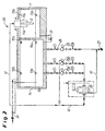
- FIG. 2 shows the two cooling basins according to FIG. 1 and illustrates the cooling water circulation for quenching the slabs/sheets.
- FIG. 3 is a schematic drawing of detail from FIG. 1 and shows a cross section through the basin that receives the located product to be cooled, which is the basin on the right in FIG. 1 .
- FIG. 4 shows a highly simplified schematic diagram of a cooling process to be carried out in the cooling installation shown in FIG. 1 .
- FIG. 5 shows a highly simplified schematic diagram of another cooling process to be carried out in the cooling installation according to FIG. 2 .
- the cooling installation 20 shown in FIG. 1 consists of a cooling basin 1 and a pump receiving basin 14 adjacent to it.
- the two basins 1 and 14 are connected with each other by flow connections in the form of a lower and an upper overflow 15 a and 15 b , respectively.
- the hot slabs/sheets 2 are fed, e.g., after austenitization, into the cooling installation 20 positioned over a traversing platform 17 and lying on a furnace car 16 arriving from a heating furnace.
- a hydraulically operated tilting device 18 is used to raise the hot slab/sheet 2 from the furnace car 16 , erect it vertically on edge, and transfer it to a carriage 3 that can be raised and lowered.
- the tilting device 18 which is assigned to the front, right cooling or quenching basin 1 , has a rotatably supported shaft 19 , on which lifting arms 21 are supported, which are in a horizontal position to receive the slab/sheet 2 and can be passed by the furnace car 16 with the supported slab/sheet 2 .
- the lifting arms 21 are turned or swiveled 90° by hydraulic cylinders 22 from the horizontal position to the transfer position, in which the slab/sheet 2 is positioned vertically on edge.
- the slab/sheet 2 is supported on its bottom edge by latches 23 , which can be acted upon by hydraulic cylinders 24 .
- Position is detected by a position sensor (not shown), and the fed slab/sheet 2 is erected after manual release into an automatic sequence.
- the carriage 3 To receive the slab/sheet 2 , the carriage 3 is raised slightly, which causes the slab/sheet 2 to be released from the latches 23 , which can then be swung out of the way. The carriage 3 is then lowered very quickly to cool the slab/sheet 2 . After complete cooling, the slab/sheet 2 is removed in automatic mode in the reverse manner from that described above for locating the slab/sheet. The cooled slab/sheet 2 then lies either on the furnace car 16 again or can be removed with the bay crane. In the case of removal with the bay crane, the traversing platform 17 must be moved laterally.
- FIG. 3 shows a slab 2 that has been set vertically on edge and placed in the carriage 3 .
- the carriage 3 is connected to a cable drive 4 , which has cables 7 , which are guided by cable drums 5 mounted on the carriage 3 after running over guide pulleys 6 .
- a frequency-controlled three-phase motor (not shown) with reduction gearing acts on the cable drums 5 by mechanical coupling by Cardan shafts.
- the carriage 3 which is guided by rollers or wheels 8 , runs on tracks 9 provided in the cooling basin 1 .
- the position of the carriage 3 and slab 2 in which they are completely lowered into the cooling basin 1 is indicated in FIG. 3 by broken lines.
- Nozzle banks 11 a , 11 b (cf. FIGS. 4 and 5 ), which are installed in the cooling basin 1 between the tracks 9 and have nozzles 10 that are directed towards the broadside surfaces of the slab/sheet 2 , are assigned to the slabs/sheets 2 that have been positioned as described above.
- the nozzle banks 11 a , 11 b are connected to a cooling water circulation 12 , as FIG. 2 shows in greater detail.
- the cooling water circulation 12 allows variable cooling and cooling processes and ensures the supply of the nozzle banks 11 a , 11 b in the quenching basin 1 for cooling slabs/sheets 2 both in a pure jet operation and in the manner of a whirlpool operation.
- cooling water is directed towards the slab/sheet 2 by the nozzle banks 11 a , 11 b .
- the cooling water is drawn in from the pump receiving tank 14 by the pumps 25 a , 25 b and pumped through a filter 26 to the nozzle banks 11 a , 11 b .
- a speed controller for the pumps 25 a , 25 b allows well-defined cooling water delivery, depending on the size and thickness of the sheet.
- the filter 26 has the function of retaining particles of scale that are larger than the nozzle orifices and could thus clog the nozzles. It is flushed with its own medium after each cooling operation. The flushing water is conveyed to a scale drain channel 27 , which also helps to lower the water level after the cooling process. Most of the scale settles at the bottom of the cooling basin 1 , so that the bottom of the basin must be cleaned from time to time.
- the water running off the slab/sheet 2 is collected in the basin 1 , from which it enters the pump receiving basin 14 through an overflow 15 a.
- FIG. 5 shows a highly schematic drawing of this cooling process.
- a make-up water and wastewater connection 28 (cf. FIG. 2 ) remains closed during the cooling. Due to the low storage volume in the jet operation, the permissible upper limit of the water temperature can already be reached in a single cooling. operation. Therefore, after the cooling process, a portion of the heated water is pumped out into the scale drain channel 27 by a pump 29 . Fresh water from a direct cooling water intake 30 is then supplied until the initial temperature is reached again.
- the amount by which the water level is lowered and the amount of fresh water that must be resupplied depend on the final temperature of the last process and on the initial temperature of the next cooling process.
- the amount of water removed and the amount of fresh water resupplied are controlled via the level in the pump receiving basin 14 .
- the level in the basin 1 can be additionally lowered by a bypass 31 .
- FIG. 4 shows another cooling process, again in a highly schematic way.
- a quenching process involving a whirlpool operation i.e., with a constant powerful flow, is made possible, as is also indicated in FIG. 3 by the wave lines in the cooling basin.
- the slab/sheet 2 is immersed in the basin 1 , which is filled to the high water level 13 b , and at the same time is acted upon by water from the cooling banks 11 a , 11 b .
- the water is forced to circulate by the nozzles 10 —free convection becomes forced convection, which allows better heat transfer from the slab/sheet 2 to the water than a simple immersion bath.
- the function of the filter 26 and the pumps 25 a , 25 b and the pump 29 is fresh water control, the same as in the jet operation. However, due to the greater storage volume in the whirlpool operation, a higher initial cooling temperature is possible, or, starting from a low initial cooling temperature, several cooling operations can be carried out until the permissible upper limit of the water temperature is reached.
- the same cooling installation 20 without additional units of equipment, to change the cooling processes, for which a cooling model is stored.
- the entire cooling process is controlled according to a physical-mathematical cooling model by a master computer, which also allows automatic control of the water temperature, the water pressure, the volume flow, and the distance of the nozzles of the nozzle banks from the surface of the slab or sheet.
- a master computer which also allows automatic control of the water temperature, the water pressure, the volume flow, and the distance of the nozzles of the nozzle banks from the surface of the slab or sheet.
- cooling by an immersion operation without directing jets of water against the slab or sheet is also optionally possible in the same cooling installation 20 .
Landscapes
- Engineering & Computer Science (AREA)
- Chemical & Material Sciences (AREA)
- Mechanical Engineering (AREA)
- Physics & Mathematics (AREA)
- Thermal Sciences (AREA)
- Crystallography & Structural Chemistry (AREA)
- Materials Engineering (AREA)
- Metallurgy (AREA)
- Organic Chemistry (AREA)
- Heat Treatments In General, Especially Conveying And Cooling (AREA)
- Heat Treatment Of Articles (AREA)
Applications Claiming Priority (7)
| Application Number | Priority Date | Filing Date | Title |
|---|---|---|---|
| DE10320651 | 2003-05-07 | ||
| DE10320651.5 | 2003-05-07 | ||
| DE10320651 | 2003-05-07 | ||
| DE102004023031 | 2004-05-06 | ||
| DE102004023031.5 | 2004-05-06 | ||
| DE102004023031A DE102004023031A1 (de) | 2003-05-07 | 2004-05-06 | Verfahren und Vorrichtung zum Kühlen bzw. Abschrecken von Brammen und Blechen mit Wasser in einem Kühlbecken |
| PCT/EP2004/004830 WO2004098804A1 (de) | 2003-05-07 | 2004-05-06 | Verfahren und vorrichtung zum kühlen bzw. abschrecken von brammen und blechen mit wasser in einem kühlbecken |
Publications (2)
| Publication Number | Publication Date |
|---|---|
| US20060292513A1 US20060292513A1 (en) | 2006-12-28 |
| US8043086B2 true US8043086B2 (en) | 2011-10-25 |
Family
ID=33435963
Family Applications (1)
| Application Number | Title | Priority Date | Filing Date |
|---|---|---|---|
| US10/555,854 Expired - Fee Related US8043086B2 (en) | 2003-05-07 | 2004-05-06 | Method and device for cooling or quenching slabs and sheets with water in a cooling pond |
Country Status (9)
| Country | Link |
|---|---|
| US (1) | US8043086B2 (de) |
| EP (1) | EP1626822B1 (de) |
| AT (1) | ATE343438T1 (de) |
| BR (1) | BRPI0410088A (de) |
| CA (1) | CA2532719C (de) |
| DE (1) | DE502004001860D1 (de) |
| ES (1) | ES2274451T3 (de) |
| RU (1) | RU2353673C2 (de) |
| WO (1) | WO2004098804A1 (de) |
Cited By (1)
| Publication number | Priority date | Publication date | Assignee | Title |
|---|---|---|---|---|
| US20220112037A1 (en) * | 2019-12-11 | 2022-04-14 | Symbotic Canada, Ulc | Case reorientation system and method |
Families Citing this family (4)
| Publication number | Priority date | Publication date | Assignee | Title |
|---|---|---|---|---|
| JP5121039B2 (ja) * | 2005-01-19 | 2013-01-16 | 新日鐵住金株式会社 | 鋼片の水冷方法 |
| ITMI20111072A1 (it) * | 2011-06-14 | 2012-12-15 | Eagle Tech S R L | Dispositivo atto a consentire il raffreddamento controllato di billette metalliche da estrudere a caldo e metodo di trattamento relativo. |
| CN107388694A (zh) * | 2017-08-31 | 2017-11-24 | 盛红梅 | 一种工件冷却系统 |
| WO2020012222A1 (en) * | 2018-07-11 | 2020-01-16 | Arcelormittal | Method to control the cooling of a metal product |
Citations (22)
| Publication number | Priority date | Publication date | Assignee | Title |
|---|---|---|---|---|
| US2341766A (en) * | 1941-12-12 | 1944-02-15 | Vernie A Fox | Rapid-quench heat-treating oven |
| US3186698A (en) * | 1963-06-14 | 1965-06-01 | Midland Ross Corp | Heat treating apparatus |
| US3323577A (en) * | 1965-05-05 | 1967-06-06 | Olin Mathieson | Process for cooling metal |
| US3556877A (en) * | 1967-04-03 | 1971-01-19 | Mitsubishi Heavy Ind Ltd | Method for hardening a tubular shaped structure |
| US3680344A (en) * | 1970-01-20 | 1972-08-01 | Bwg Bergwerk Walzwerk | System for cooling large, hot metal slabs |
| US3706544A (en) * | 1971-07-19 | 1972-12-19 | Ppg Industries Inc | Method of liquid quenching of glass sheets |
| US3725024A (en) * | 1971-01-21 | 1973-04-03 | Ppg Industries Inc | Tempering glass sheets with liquid flows |
| US3738629A (en) * | 1971-03-04 | 1973-06-12 | Dorn Co V | Bar quench fixture |
| US3782916A (en) * | 1971-09-13 | 1974-01-01 | Triplex Safety Glass Co | Production of toughened and bent glass sheets |
| US3829072A (en) * | 1972-11-13 | 1974-08-13 | A Fieser | Metal slab conditioning system |
| US3870570A (en) * | 1972-11-13 | 1975-03-11 | Arthur H Fieser | Method for conditioning metal slabs |
| US3942967A (en) * | 1973-07-20 | 1976-03-09 | Triplex Safety Glass Company Limited | Heat treatment of glass sheets |
| DE2548154A1 (de) | 1975-10-28 | 1977-05-05 | Sack Gmbh Maschf | Kuehlvorrichtung fuer brammen mit brammenkippstuehlen zum wenden des walzgutes |
| JPS5266811A (en) | 1975-12-01 | 1977-06-02 | Nippon Steel Corp | Bright cooling of steel sheet |
| US4036243A (en) * | 1975-07-07 | 1977-07-19 | Bwg Bergwerk-Und Walzwerk Maschinenbau G.M.B.H. | Apparatus for cooling hot slabs |
| JPS5934771A (ja) | 1982-08-20 | 1984-02-25 | Casio Comput Co Ltd | ポ−タブルテレビジヨン受像機 |
| JPS609834A (ja) | 1983-06-28 | 1985-01-18 | Nippon Steel Corp | 鋼ストリツプの冷却方法及びその装置 |
| EP0195658A2 (de) | 1985-03-22 | 1986-09-24 | Kawasaki Steel Corporation | Verfahren und Vorrichtung zum Kühlen von Stahlband |
| EP0755732A1 (de) | 1995-07-27 | 1997-01-29 | POMINI S.p.A. | Anlage zur In-line-Wärmebehandlung für warmgewalzte Produkte |
| US5795538A (en) * | 1993-01-27 | 1998-08-18 | Dowa Mining Co., Ltd. | Apparatus for steel hardening and process therefor |
| US5820705A (en) * | 1993-05-18 | 1998-10-13 | Aluminum Company Of America | Spray quenching of metal with liquid coolant containing dissolved gas |
| EP0960670A1 (de) | 1998-05-28 | 1999-12-01 | Kawasaki Steel Corporation | Verfahren zum Kühlen von Brammen mit Wasser und Wasserkühlbecken |
Family Cites Families (2)
| Publication number | Priority date | Publication date | Assignee | Title |
|---|---|---|---|---|
| SU1320245A1 (ru) * | 1986-10-14 | 1987-06-30 | Днепропетровский Металлургический Институт Им.Л.И.Брежнева | Устройство дл закалки металлических изделий |
| SU1502638A1 (ru) * | 1987-01-21 | 1989-08-23 | Колпинское Отделение Всесоюзного Научно-Исследовательского И Проектно-Конструкторского Института Металлургического Машиностроения Им. А.И.Целикова | Устройство дл охлаждени толстых листов |
-
2004
- 2004-05-06 WO PCT/EP2004/004830 patent/WO2004098804A1/de not_active Ceased
- 2004-05-06 US US10/555,854 patent/US8043086B2/en not_active Expired - Fee Related
- 2004-05-06 DE DE502004001860T patent/DE502004001860D1/de not_active Expired - Lifetime
- 2004-05-06 CA CA2532719A patent/CA2532719C/en not_active Expired - Fee Related
- 2004-05-06 ES ES04731341T patent/ES2274451T3/es not_active Expired - Lifetime
- 2004-05-06 BR BRPI0410088-3A patent/BRPI0410088A/pt not_active Application Discontinuation
- 2004-05-06 AT AT04731341T patent/ATE343438T1/de active
- 2004-05-06 EP EP04731341A patent/EP1626822B1/de not_active Expired - Lifetime
- 2004-05-06 RU RU2005138038/02A patent/RU2353673C2/ru active
Patent Citations (26)
| Publication number | Priority date | Publication date | Assignee | Title |
|---|---|---|---|---|
| US2341766A (en) * | 1941-12-12 | 1944-02-15 | Vernie A Fox | Rapid-quench heat-treating oven |
| US3186698A (en) * | 1963-06-14 | 1965-06-01 | Midland Ross Corp | Heat treating apparatus |
| US3323577A (en) * | 1965-05-05 | 1967-06-06 | Olin Mathieson | Process for cooling metal |
| US3556877A (en) * | 1967-04-03 | 1971-01-19 | Mitsubishi Heavy Ind Ltd | Method for hardening a tubular shaped structure |
| US3680344A (en) * | 1970-01-20 | 1972-08-01 | Bwg Bergwerk Walzwerk | System for cooling large, hot metal slabs |
| US3725024A (en) * | 1971-01-21 | 1973-04-03 | Ppg Industries Inc | Tempering glass sheets with liquid flows |
| US3738629A (en) * | 1971-03-04 | 1973-06-12 | Dorn Co V | Bar quench fixture |
| US3706544A (en) * | 1971-07-19 | 1972-12-19 | Ppg Industries Inc | Method of liquid quenching of glass sheets |
| US3782916A (en) * | 1971-09-13 | 1974-01-01 | Triplex Safety Glass Co | Production of toughened and bent glass sheets |
| US3829072A (en) * | 1972-11-13 | 1974-08-13 | A Fieser | Metal slab conditioning system |
| US3870570A (en) * | 1972-11-13 | 1975-03-11 | Arthur H Fieser | Method for conditioning metal slabs |
| US3942967A (en) * | 1973-07-20 | 1976-03-09 | Triplex Safety Glass Company Limited | Heat treatment of glass sheets |
| US4036243A (en) * | 1975-07-07 | 1977-07-19 | Bwg Bergwerk-Und Walzwerk Maschinenbau G.M.B.H. | Apparatus for cooling hot slabs |
| DE2548154A1 (de) | 1975-10-28 | 1977-05-05 | Sack Gmbh Maschf | Kuehlvorrichtung fuer brammen mit brammenkippstuehlen zum wenden des walzgutes |
| US4088309A (en) | 1975-10-28 | 1978-05-09 | Sack Gmbh | Cooling device for slabs with slab-tilting devices for turning the rolled stock |
| JPS5266811A (en) | 1975-12-01 | 1977-06-02 | Nippon Steel Corp | Bright cooling of steel sheet |
| JPS5934771A (ja) | 1982-08-20 | 1984-02-25 | Casio Comput Co Ltd | ポ−タブルテレビジヨン受像機 |
| JPS609834A (ja) | 1983-06-28 | 1985-01-18 | Nippon Steel Corp | 鋼ストリツプの冷却方法及びその装置 |
| EP0195658A2 (de) | 1985-03-22 | 1986-09-24 | Kawasaki Steel Corporation | Verfahren und Vorrichtung zum Kühlen von Stahlband |
| JPS61217531A (ja) | 1985-03-22 | 1986-09-27 | Kawasaki Steel Corp | 鋼帯の冷却方法 |
| US5795538A (en) * | 1993-01-27 | 1998-08-18 | Dowa Mining Co., Ltd. | Apparatus for steel hardening and process therefor |
| US5820705A (en) * | 1993-05-18 | 1998-10-13 | Aluminum Company Of America | Spray quenching of metal with liquid coolant containing dissolved gas |
| EP0755732A1 (de) | 1995-07-27 | 1997-01-29 | POMINI S.p.A. | Anlage zur In-line-Wärmebehandlung für warmgewalzte Produkte |
| US5679307A (en) * | 1995-07-27 | 1997-10-21 | Pomini S.P.A. | Facility for in-line heat treatment of hot-rolled products |
| EP0960670A1 (de) | 1998-05-28 | 1999-12-01 | Kawasaki Steel Corporation | Verfahren zum Kühlen von Brammen mit Wasser und Wasserkühlbecken |
| US6250370B1 (en) * | 1998-05-28 | 2001-06-26 | Kawasaki Steel Corporation | Method for water-cooling hot metal slabs |
Cited By (2)
| Publication number | Priority date | Publication date | Assignee | Title |
|---|---|---|---|---|
| US20220112037A1 (en) * | 2019-12-11 | 2022-04-14 | Symbotic Canada, Ulc | Case reorientation system and method |
| US11584595B2 (en) * | 2019-12-11 | 2023-02-21 | Symbotic Canada, Ulc | Case reorientation system and method |
Also Published As
| Publication number | Publication date |
|---|---|
| DE502004001860D1 (de) | 2006-12-07 |
| CA2532719A1 (en) | 2004-11-18 |
| CA2532719C (en) | 2010-10-19 |
| BRPI0410088A (pt) | 2006-05-16 |
| RU2353673C2 (ru) | 2009-04-27 |
| EP1626822A1 (de) | 2006-02-22 |
| RU2005138038A (ru) | 2006-05-10 |
| ATE343438T1 (de) | 2006-11-15 |
| ES2274451T3 (es) | 2007-05-16 |
| EP1626822B1 (de) | 2006-10-25 |
| WO2004098804A1 (de) | 2004-11-18 |
| US20060292513A1 (en) | 2006-12-28 |
Similar Documents
| Publication | Publication Date | Title |
|---|---|---|
| JP4897478B2 (ja) | スラブ或いはシートを冷却槽内の水中で冷却する、或いは焼入れする装置 | |
| CN102925633B (zh) | 一种钢板淬火冷却方法及设备 | |
| CN103834791A (zh) | 一种钢板连续辊式淬火冷却系统 | |
| US8043086B2 (en) | Method and device for cooling or quenching slabs and sheets with water in a cooling pond | |
| US1959215A (en) | Process and apparatus for making case hardened glass | |
| CN101868557B (zh) | 轨道的热处理的工艺和装置 | |
| CN110756777B (zh) | 一种泡沫铝生产工艺线及其生产工艺 | |
| KR101189515B1 (ko) | 스케일 제거장치 및 제거방법 | |
| JP2010024516A (ja) | 高周波焼入装置の浸漬冷却装置 | |
| JP3349117B2 (ja) | 横型酸洗装置 | |
| CN107653373A (zh) | 一种电机轴淬火装置 | |
| KR101225298B1 (ko) | 철근 침적장치 | |
| CN112522479B (zh) | 一种钢管或圆棒的冷却方法 | |
| JP5114655B2 (ja) | ルーズコイルの冷却設備及び冷却方法 | |
| CN114317912B (zh) | 一种淬火介质可快速流动的淬火装置 | |
| CN105803167B (zh) | 直立式板坯淬火机及淬火方法 | |
| CN205741111U (zh) | 直立式板坯淬火机 | |
| CN107949659A (zh) | 酸洗装置 | |
| CN117286505A (zh) | 一种酸洗装置及酸洗方法 | |
| US2317233A (en) | Method and apparatus for hardening steel rolls | |
| KR20040019736A (ko) | 고온빌렛의 침적냉각장치 | |
| JP7551734B2 (ja) | 熱交換液槽用の移動可能なタンクおよびそのようなタンクを備える設備 | |
| JPH08253807A (ja) | 熱処理される連続鋳造片の鋳片支持装置 | |
| KR20200061588A (ko) | 강재 냉각 장치 및 방법 | |
| JPH0734130A (ja) | 焼き入れ方法および熱処理装置 |
Legal Events
| Date | Code | Title | Description |
|---|---|---|---|
| AS | Assignment |
Owner name: SMS DEMAG AG, GERMANY Free format text: ASSIGNMENT OF ASSIGNORS INTEREST;ASSIGNORS:SCHMIDT, DIRK;WEHAGE, HARALD;WERNER, FRANK;AND OTHERS;SIGNING DATES FROM 20051021 TO 20051028;REEL/FRAME:017955/0055 Owner name: SMS DEMAG AG, GERMANY Free format text: ASSIGNMENT OF ASSIGNORS INTEREST;ASSIGNORS:SCHMIDT, DIRK;WEHAGE, HARALD;WERNER, FRANK;AND OTHERS;REEL/FRAME:017955/0055;SIGNING DATES FROM 20051021 TO 20051028 |
|
| AS | Assignment |
Owner name: SMS SIEMAG AKTIENGESELLSCHAFT, GERMANY Free format text: CHANGE OF NAME;ASSIGNOR:SMS DEMAG AG;REEL/FRAME:023725/0342 Effective date: 20090325 Owner name: SMS SIEMAG AKTIENGESELLSCHAFT,GERMANY Free format text: CHANGE OF NAME;ASSIGNOR:SMS DEMAG AG;REEL/FRAME:023725/0342 Effective date: 20090325 |
|
| FEPP | Fee payment procedure |
Free format text: PAYOR NUMBER ASSIGNED (ORIGINAL EVENT CODE: ASPN); ENTITY STATUS OF PATENT OWNER: LARGE ENTITY |
|
| ZAAA | Notice of allowance and fees due |
Free format text: ORIGINAL CODE: NOA |
|
| ZAAB | Notice of allowance mailed |
Free format text: ORIGINAL CODE: MN/=. |
|
| STCF | Information on status: patent grant |
Free format text: PATENTED CASE |
|
| FPAY | Fee payment |
Year of fee payment: 4 |
|
| MAFP | Maintenance fee payment |
Free format text: PAYMENT OF MAINTENANCE FEE, 8TH YEAR, LARGE ENTITY (ORIGINAL EVENT CODE: M1552); ENTITY STATUS OF PATENT OWNER: LARGE ENTITY Year of fee payment: 8 |
|
| FEPP | Fee payment procedure |
Free format text: MAINTENANCE FEE REMINDER MAILED (ORIGINAL EVENT CODE: REM.); ENTITY STATUS OF PATENT OWNER: LARGE ENTITY |
|
| LAPS | Lapse for failure to pay maintenance fees |
Free format text: PATENT EXPIRED FOR FAILURE TO PAY MAINTENANCE FEES (ORIGINAL EVENT CODE: EXP.); ENTITY STATUS OF PATENT OWNER: LARGE ENTITY |
|
| STCH | Information on status: patent discontinuation |
Free format text: PATENT EXPIRED DUE TO NONPAYMENT OF MAINTENANCE FEES UNDER 37 CFR 1.362 |
|
| FP | Lapsed due to failure to pay maintenance fee |
Effective date: 20231025 |