US805437A - Door-lock. - Google Patents
Door-lock. Download PDFInfo
- Publication number
- US805437A US805437A US1905248253A US805437A US 805437 A US805437 A US 805437A US 1905248253 A US1905248253 A US 1905248253A US 805437 A US805437 A US 805437A
- Authority
- US
- United States
- Prior art keywords
- latch
- head
- lock
- shank
- knob
- Prior art date
- Legal status (The legal status is an assumption and is not a legal conclusion. Google has not performed a legal analysis and makes no representation as to the accuracy of the status listed.)
- Expired - Lifetime
Links
- 238000010276 construction Methods 0.000 description 3
Images
Classifications
-
- E—FIXED CONSTRUCTIONS
- E05—LOCKS; KEYS; WINDOW OR DOOR FITTINGS; SAFES
- E05B—LOCKS; ACCESSORIES THEREFOR; HANDCUFFS
- E05B55/00—Locks in which a sliding latch is used also as a locking bolt
-
- Y—GENERAL TAGGING OF NEW TECHNOLOGICAL DEVELOPMENTS; GENERAL TAGGING OF CROSS-SECTIONAL TECHNOLOGIES SPANNING OVER SEVERAL SECTIONS OF THE IPC; TECHNICAL SUBJECTS COVERED BY FORMER USPC CROSS-REFERENCE ART COLLECTIONS [XRACs] AND DIGESTS
- Y10—TECHNICAL SUBJECTS COVERED BY FORMER USPC
- Y10T—TECHNICAL SUBJECTS COVERED BY FORMER US CLASSIFICATION
- Y10T70/00—Locks
- Y10T70/50—Special application
- Y10T70/5093—For closures
- Y10T70/5155—Door
- Y10T70/5199—Swinging door
- Y10T70/5372—Locking latch bolts, biased
- Y10T70/5385—Spring projected
- Y10T70/5389—Manually operable
- Y10T70/55—Dogged bolt or connections
Definitions
- This invention relates to door-locks.
- the object of the invention is to dispense with the ordinary locking-bolt and in lieu thereof in a novel and practical manner to make the knob-latch perform the double function of a latch and a bolt.
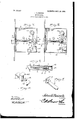
- Figure 1 is a view in elevation of a .lock with one of the plates removed to eX- hibit the interior mechanism, the parts being in the position that they occupy when the knob-latch can be actuated by the knob.
- Fig. 2 is a similar view showing the position of the parts when they are locked against movement by the knob.
- Fig. 3 is a view in vertical longitudinal section taken on the line 3 3, Fig. 1, and looking in the direction of the arrow thereon.
- Fig. 4 is a perspective detail view of the bolt.
- Fig. 5 is a similar view of the tumbler. y
- 1 designates the casing, which may be of the usual or any preferred construction, and as the same forms no partof the present invention detailed description thereof is omitted.
- knob-latch 2 Arranged within the casing is a knob-latch 2, the shank 3 of which in this instance is shown as circular in cross-section, although it may be of other contours, and carries on its inner end a head l, which is here shown as combined with the shank by a threaded connection, although this is not essential, as
- a tumbler 6 having a head 7, provided with an orifice 8, through which the shank 3 projects, the head being designed to engage with the guides 5, against which they are held by a coil-spring mounted upon the shank and bearing at one end against the head and the opposite end against the latch, the object of this being, as usual, to hold the latch normally projected beyond the face of the casing.
- the latch is retracted as usual by an arm 10, carried by a knob-shank hub 11, which is rotatably mounted in bearings formed in the two sides of the casing.
- the free end of this arm is disposed between the head 4 and the guides, as clearly shown in Figs. 1 and 2, the said guides operating in conjunction with the arm to limit the forward projection of the latch, and thus cause it always to project only a predetermined distance beyond the casing.
- the means for locking the latch against retraction consists of a bolt 12, having intermediate of its ends an abutment 13, preferably cubical in form, and which is adapted to be shifted by the movement of the bolt by the key into the path of movement of the head 4, as shown in Fig. 2, thereby positively to hold the latch against inward movement.
- the bolt is provided on one end with a plurality of tumbler-seats 14-in this instance two, one of which is engaged by the tumbler to hold the abutment out of the path of movement of the latch-head and the other of which is engaged by the tumbler to hold the abutment in the path of movement of the latch-head.
- the other end of the bolt is provided with a keyward notch 15, of the usual or any preferred construction.
- the casing is provided with an ordinary keyhole 16, adjacent to which are secured the wards 17, which will be constructed to suit the character of key employed.
- knob-shank hub carrying an arm having its free end disposed between the head and one of the guides, a tumbler projecting between the guides and having a head through which the shank projects, a spring mounted on the shank and bearing at one end against the tumbler-head, and a bolt having an abutment adapted to be moved into and out of the path of movement of the shank-head and provided with seats to be engaged by the tumbler to lock the bolt at the desired adjustment.
Landscapes
- Lock And Its Accessories (AREA)
Description
No. 805,437. PATBNTED NOV. 28, 1905. J. G. BAISGH. DOOR LOCK.
APPLICATION FILED MARS, 1905.
Witnesses; Inventor,
by f l /l l f n Attorneys.
JOHN G. BAISOH, OF GRAND RAPIDS, MICHIGAN.
DOOR-LOCK.
Specification of Letters Patent.
` Patented Nov. 28,1905.
Application tiled March 3, 1905. Serial No. 248,253.
To all who/1t it Nuty con/cern,.-
Be it known that I, JOHN G. BAiscH, a citizen of the United States, residing at Grand Rapids, in the county of Kent and State of Michigan, have invented a new and useful Door-Lock, of which the following is a speciiication.
This invention relates to door-locks.
The object of the invention is to dispense with the ordinary locking-bolt and in lieu thereof in a novel and practical manner to make the knob-latch perform the double function of a latch and a bolt.
With these and other objects in view, as will lappear as the nature of the invention is better understood, the same consists in the novel construction and combination of parts of a lock, as will be hereinafter fully described and claimed.
In the accompanying drawings, forming a part of this specification, and in which like characters of reference indicate corresponding parts, Figure 1 is a view in elevation of a .lock with one of the plates removed to eX- hibit the interior mechanism, the parts being in the position that they occupy when the knob-latch can be actuated by the knob.
Fig. 2 is a similar view showing the position of the parts when they are locked against movement by the knob. Fig. 3 is a view in vertical longitudinal section taken on the line 3 3, Fig. 1, and looking in the direction of the arrow thereon. Fig. 4 is a perspective detail view of the bolt. Fig. 5 is a similar view of the tumbler. y
Vhile the imprcvementsof the present invention are herein shown as combined with a mortise-lock, it is to be understood that they are equally adaptable for use in connection with a rim-lock, and as this will be readily understood detailed illustration of the latter arrangement is deemed unnecessary.
Referring to the drawings, 1 designates the casing, which may be of the usual or any preferred construction, and as the same forms no partof the present invention detailed description thereof is omitted.
Arranged within the casing is a knob-latch 2, the shank 3 of which in this instance is shown as circular in cross-section, although it may be of other contours, and carries on its inner end a head l, which is here shown as combined with the shank by a threaded connection, although this is not essential, as
it may be otherwise secured if preferred. Arranged near the rear side of the casing are two upstanding guides 5, between which the shank works, thereby to cause the head of the latch always to move in a right line.
Combined with the shank is a tumbler 6, having a head 7, provided with an orifice 8, through which the shank 3 projects, the head being designed to engage with the guides 5, against which they are held by a coil-spring mounted upon the shank and bearing at one end against the head and the opposite end against the latch, the object of this being, as usual, to hold the latch normally projected beyond the face of the casing.
The latch is retracted as usual by an arm 10, carried by a knob-shank hub 11, which is rotatably mounted in bearings formed in the two sides of the casing. The free end of this arm is disposed between the head 4 and the guides, as clearly shown in Figs. 1 and 2, the said guides operating in conjunction with the arm to limit the forward projection of the latch, and thus cause it always to project only a predetermined distance beyond the casing.
The means for locking the latch against retraction consists of a bolt 12, having intermediate of its ends an abutment 13, preferably cubical in form, and which is adapted to be shifted by the movement of the bolt by the key into the path of movement of the head 4, as shown in Fig. 2, thereby positively to hold the latch against inward movement. The bolt is provided on one end with a plurality of tumbler-seats 14-in this instance two, one of which is engaged by the tumbler to hold the abutment out of the path of movement of the latch-head and the other of which is engaged by the tumbler to hold the abutment in the path of movement of the latch-head. The other end of the bolt is provided with a keyward notch 15, of the usual or any preferred construction.
The casing is provided with an ordinary keyhole 16, adjacent to which are secured the wards 17, which will be constructed to suit the character of key employed.
It will be seen from the foregoing descrip. tion that by the arrangement herein shown a positive locking of the latch against movement can be effected, so that the latch in reality constitutes a bolt, and, further, when IOO used as a knob-latch pure and simple it will be as eiiective in operation as with ordinary knob-latches in ordinary use.
I-Iaving thus described the invention,what is claimed is* l. In a lock, the combination with a casing, of a pair of guides, a knob-latch having a shank disposed between the guides and provided at its inner end with a head, a tuinbler projecting between the guides and havinU a head mounted upon the shank, and a bozlt having an abutment to be moved into and out of the path of movement oi' the head and provided with seats to be engaged by the tumbler to hold the bolt in operative or inoperative positions relatively to the latch.
2. The combination with a lock-casing provided with a pair of' guides, of a knob-latch having a shank working between the guides and provided on its inner end with a head, a
knob-shank hub carrying an arm having its free end disposed between the head and one of the guides, a tumbler projecting between the guides and having a head through which the shank projects, a spring mounted on the shank and bearing at one end against the tumbler-head, and a bolt having an abutment adapted to be moved into and out of the path of movement of the shank-head and provided with seats to be engaged by the tumbler to lock the bolt at the desired adjustment. y
In testimony that I claim the foregoing as my own I have hereto aHiXed my signature in the presence of two witnesses.
JOHN G. BAISCII Witnesses CHARLES ALBERT BAIsoH, STANLEY JAoKowsKr.
Priority Applications (1)
| Application Number | Priority Date | Filing Date | Title |
|---|---|---|---|
| US1905248253 US805437A (en) | 1905-03-03 | 1905-03-03 | Door-lock. |
Applications Claiming Priority (1)
| Application Number | Priority Date | Filing Date | Title |
|---|---|---|---|
| US1905248253 US805437A (en) | 1905-03-03 | 1905-03-03 | Door-lock. |
Publications (1)
| Publication Number | Publication Date |
|---|---|
| US805437A true US805437A (en) | 1905-11-28 |
Family
ID=2873920
Family Applications (1)
| Application Number | Title | Priority Date | Filing Date |
|---|---|---|---|
| US1905248253 Expired - Lifetime US805437A (en) | 1905-03-03 | 1905-03-03 | Door-lock. |
Country Status (1)
| Country | Link |
|---|---|
| US (1) | US805437A (en) |
Cited By (2)
| Publication number | Priority date | Publication date | Assignee | Title |
|---|---|---|---|---|
| US2653045A (en) * | 1950-04-25 | 1953-09-22 | Pinderhughes William | Electric door lock |
| US2680036A (en) * | 1950-03-01 | 1954-06-01 | Gill William Albert | Door latch |
-
1905
- 1905-03-03 US US1905248253 patent/US805437A/en not_active Expired - Lifetime
Cited By (2)
| Publication number | Priority date | Publication date | Assignee | Title |
|---|---|---|---|---|
| US2680036A (en) * | 1950-03-01 | 1954-06-01 | Gill William Albert | Door latch |
| US2653045A (en) * | 1950-04-25 | 1953-09-22 | Pinderhughes William | Electric door lock |
Similar Documents
| Publication | Publication Date | Title |
|---|---|---|
| US805437A (en) | Door-lock. | |
| US1070178A (en) | Lock mechanism. | |
| US266903A (en) | Half to charles h | |
| US170353A (en) | Improvement in locking-latches | |
| US57423A (en) | Improvement in locks | |
| US771542A (en) | Latch. | |
| US1255106A (en) | Door-lock. | |
| US770408A (en) | Nelson d | |
| US1105152A (en) | Lock and latch. | |
| US194000A (en) | Improvement in door-bolts | |
| US1228129A (en) | Latch. | |
| US1219318A (en) | Latch. | |
| US248847A (en) | clime | |
| US47470A (en) | Improvement in locks | |
| US477036A (en) | Cylinder-lock | |
| US1143492A (en) | Combined lock and latch. | |
| US586675A (en) | Warren ii | |
| US356013A (en) | bobebtson | |
| US868897A (en) | Lock. | |
| US400111A (en) | Latch and lock combined | |
| US4659A (en) | Book-lock | |
| US686166A (en) | Mortise thumb-bolt for doors. | |
| US540532A (en) | Door-bolt | |
| US687644A (en) | Latch. | |
| US1009600A (en) | Consolidated latch and dead bolt lock. |