US8063642B2 - Method for subsurface electromagnetic surveying using two or more simultaneously actuated electromagnetic sources - Google Patents
Method for subsurface electromagnetic surveying using two or more simultaneously actuated electromagnetic sources Download PDFInfo
- Publication number
- US8063642B2 US8063642B2 US12/157,471 US15747108A US8063642B2 US 8063642 B2 US8063642 B2 US 8063642B2 US 15747108 A US15747108 A US 15747108A US 8063642 B2 US8063642 B2 US 8063642B2
- Authority
- US
- United States
- Prior art keywords
- signal
- electromagnetic signal
- electromagnetic
- response
- transmitter
- Prior art date
- Legal status (The legal status is an assumption and is not a legal conclusion. Google has not performed a legal analysis and makes no representation as to the accuracy of the status listed.)
- Expired - Fee Related, expires
Links
- 238000000034 method Methods 0.000 title claims abstract description 53
- 230000004044 response Effects 0.000 claims abstract description 92
- 230000015572 biosynthetic process Effects 0.000 claims abstract description 76
- 238000005755 formation reaction Methods 0.000 claims abstract description 76
- XLYOFNOQVPJJNP-UHFFFAOYSA-N water Substances O XLYOFNOQVPJJNP-UHFFFAOYSA-N 0.000 claims description 24
- 238000005314 correlation function Methods 0.000 claims description 2
- 230000005672 electromagnetic field Effects 0.000 description 14
- 238000001228 spectrum Methods 0.000 description 9
- 238000005259 measurement Methods 0.000 description 8
- 239000011148 porous material Substances 0.000 description 8
- 238000012545 processing Methods 0.000 description 8
- 239000011435 rock Substances 0.000 description 7
- 230000008569 process Effects 0.000 description 6
- 101100371175 Homo sapiens TSPO gene Proteins 0.000 description 5
- 102100031269 Putative peripheral benzodiazepine receptor-related protein Human genes 0.000 description 5
- 230000008859 change Effects 0.000 description 5
- 230000001052 transient effect Effects 0.000 description 5
- 238000001514 detection method Methods 0.000 description 4
- 230000005684 electric field Effects 0.000 description 4
- 239000012530 fluid Substances 0.000 description 4
- 229930195733 hydrocarbon Natural products 0.000 description 3
- 150000002430 hydrocarbons Chemical class 0.000 description 3
- 229920006395 saturated elastomer Polymers 0.000 description 3
- 230000008901 benefit Effects 0.000 description 2
- 238000004062 sedimentation Methods 0.000 description 2
- 239000012267 brine Substances 0.000 description 1
- 239000004020 conductor Substances 0.000 description 1
- 238000011161 development Methods 0.000 description 1
- 230000018109 developmental process Effects 0.000 description 1
- 239000007789 gas Substances 0.000 description 1
- 238000000691 measurement method Methods 0.000 description 1
- 239000000203 mixture Substances 0.000 description 1
- 239000000615 nonconductor Substances 0.000 description 1
- 239000003921 oil Substances 0.000 description 1
- 239000003208 petroleum Substances 0.000 description 1
- 238000003908 quality control method Methods 0.000 description 1
- 238000012827 research and development Methods 0.000 description 1
- HPALAKNZSZLMCH-UHFFFAOYSA-M sodium;chloride;hydrate Chemical compound O.[Na+].[Cl-] HPALAKNZSZLMCH-UHFFFAOYSA-M 0.000 description 1
- 230000001131 transforming effect Effects 0.000 description 1
Images


Classifications
-
- G—PHYSICS
- G01—MEASURING; TESTING
- G01V—GEOPHYSICS; GRAVITATIONAL MEASUREMENTS; DETECTING MASSES OR OBJECTS; TAGS
- G01V3/00—Electric or magnetic prospecting or detecting; Measuring magnetic field characteristics of the earth, e.g. declination, deviation
- G01V3/12—Electric or magnetic prospecting or detecting; Measuring magnetic field characteristics of the earth, e.g. declination, deviation operating with electromagnetic waves
-
- G—PHYSICS
- G01—MEASURING; TESTING
- G01V—GEOPHYSICS; GRAVITATIONAL MEASUREMENTS; DETECTING MASSES OR OBJECTS; TAGS
- G01V3/00—Electric or magnetic prospecting or detecting; Measuring magnetic field characteristics of the earth, e.g. declination, deviation
- G01V3/08—Electric or magnetic prospecting or detecting; Measuring magnetic field characteristics of the earth, e.g. declination, deviation operating with magnetic or electric fields produced or modified by objects or geological structures or by detecting devices
- G01V3/083—Controlled source electromagnetic [CSEM] surveying
Definitions
- the invention is related to systems and methods for estimating the response of rock formations in the earth's subsurface to imparted electromagnetic fields in order to determine spatial distribution of electrical properties of the formations.
- Porous subsurface sedimentary rock formations are typically saturated with fluids as a result of having been deposited in a body of water during sedimentation. As a result, the fluids were initially entirely water. In some subsurface formations the water in the pore spaces has been displaced to some extent after sedimentation by hydrocarbons such as oil and gas. Thus, in some present day subsurface formations, the fluids in their pore spaces may be water, gas or oil, or mixtures of the foregoing.
- Detection of formations having less than fully water-saturated pore space, that is, when oil or gas is present in the pore spaces, is of significant economic interest.
- Certain techniques for detection of such formations include determining existence of electrical resistivities in the subsurface that are anomalously high. The principle of such detection is based on the fact that the flow of electric current through a porous rock formation is related to the fractional volume of the pore spaces with respect to the total rock volume, the spatial configuration of the pore spaces and the electrical properties of the fluids filling the pore spaces.
- Brine-saturated porous rock formations are typically much less resistive than the same rock formations having hydrocarbons in some or all of the pore spaces, because brine is a relatively good electrical conductor while hydrocarbons are typically good electrical insulators.
- Such techniques in general include imparting an electromagnetic field into the subsurface formations and measuring electric and/or magnetic fields induced in the subsurface formation in response to the imparted electromagnetic field.
- the electromagnetic field may be imparted using an electric field transmitter, for example, by passing an electric current through a dipole electrode pair.
- a magnetic field transmitter may be used, for example, passing an electric current through a wire loop or a plurality of such loops.
- the receivers used to detect the responsive electromagnetic fields may be dipole electrode pairs for measuring potential differences (electric field potential), or may be wire loops, pluralities of wire loops or magnetometers for measuring magnetic field amplitude and/or the time derivatives of magnetic field amplitude.
- the electric current used to impart the electromagnetic field may be controlled to provide a step change in the current. Step change in the transmitter current induces what are referred to as “transient” electromagnetic fields, and the responses measured by the receivers are related to transient response of the formations in the earth's subsurface. Step change in the transmitter current may be obtained by switching the current on, switching the current off, reversing polarity, or combinations of the foregoing.
- a particularly advantageous form of transmitter current switching configuration used to impart the electromagnetic field is a so called “pseudo-random binary sequence” (PRBS).
- a receiver vessel may deploy a plurality of receivers in a selected pattern, such as a line array, on the water bottom.
- a separate transmitter vessel may deploy the transmitter on or at a nominal distance from the water bottom.
- the transmitter may be actuated and signals from the receivers recorded.
- Electromagnetic signals corresponding to various offsets may be obtained by moving the transmitter vessel, actuating the transmitter, and recording signals from the receivers, successively. The transmitter current is measured during actuation and the measurements thereof can then be transmitted to the receiver vessel for data quality control and processing.
- the receiver vessel may withdraw the receivers from the water bottom, move to a different location, and once again deploy the receivers on the water bottom in a different location.
- the above-described transmitter deployment, transmitter actuation and signal recording may then be repeated.
- One possibility is to actuate more than one transmitter at approximately the same time, and record the signals generated in response. Such technique could reduce the time taken to acquire a plurality of different offset electromagnetic signals.
- a method for electromagnetic exploration includes imparting a first electromagnetic signal into subsurface formations from a first location and imparting a second electromagnetic signal into the formations from a second location substantially contemporaneously with imparting the first electromagnetic signal.
- the first and second electromagnetic signals are substantially uncorrelated with each other.
- a combined electromagnetic response of the formations to the first and second imparted electromagnetic signals is detected at a third location.
- a response of the formations to each of the first and the second imparted signals is determined from the detected response.
- Another aspect of the invention is a method for determining a formation response from a detected electromagnetic signal resulting from a first electromagnetic signal imparted into a subsurface earth formation at a first location and from a second electromagnetic signal imparted into the formation at a second location.
- the first and second signals are imparted substantially contemporaneously.
- a method according to this aspect of the invention includes (a) deconvolving the detected signal using the first electromagnetic signal; (b) estimating the formation response to the first electromagnetic signal using the deconvolved detected signal; (c) convolving the estimated formation response from (b) with the first electromagnetic signal, and (d) subtracting a result of the convolution of the estimated formation response with the first electromagnetic signal from the detected signal.
- FIG. 1 shows a typical arrangement of electromagnetic transmitter and receivers.
- FIG. 2 shows a graph of transmitter current as measured for a pseudo-random binary sequence signal.
- FIG. 3 shows a graph of voltage measured simultaneously between a pair of receiver electrodes in response to the transmitter current shown in FIG. 2 .
- FIG. 4 shows a graph of impulse response recovered by deconvolving the voltage signal of FIG. 3 with the current signal of FIG. 2 .
- FIG. 5 shows two transmitters used with one receiver in an example of a method according to the invention.
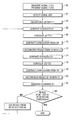
- FIG. 6 shows a flow chart of one example implementation of the invention.
- FIG. 1 A typical deployment of marine geophysical survey vessels that may be used to conduct electromagnetic geophysical surveying is shown schematically in FIG. 1 .
- a transmitter vessel 10 is deployed on the surface of a body of water 14 such as a lake or the ocean.
- the transmitter vessel 10 may deploy one or more electromagnetic transmitters 11 into the water 14 , typically near the water bottom 16 .
- the transmitter 11 may be electrodes A, B disposed along an insulated electrical cable.
- the electrodes A, B are disposed at a selected distance from each other and are coupled to a control and power supply system 10 A disposed on the transmitter vessel 10 .
- a receiver vessel 12 may also be deployed on the water 14 proximate the transmitter vessel 10 .
- the receiver vessel 12 may deploy one or more electromagnetic receivers 13 in the water 14 , typically on the water bottom 16 .
- the receiver 13 may be a plurality of electrodes C, D disposed along an insulated electrical cable.
- the electrodes C, D may be configured to detect voltages resulting from electromagnetic fields induced in the subsurface by the transmitter 11 being energized.
- the voltages imparted across the electrodes C, D. may be detected by a recording system 12 A disposed on the receiver vessel 12 , or may be communicated for storage in a recording buoy 18 at a distal end of the receiver cable.
- Actuation of the transmitter 11 is performed by imparting electric current across the transmitter electrodes A, B.
- the system shown in FIG. 1 includes transmitter and receivers referred to as horizontal electric dipoles.
- any other known form of electromagnetic transmitter and receiver for example, vertical electric dipoles (pairs of electrodes oriented vertically), horizontal magnetic dipoles (wire coils oriented so that the longitudinal axis of the coils is horizontal) and vertical magnetic dipoles (the vertical magnetic analog of the vertical electric dipole) may be used in other examples, as well as magnetometers for detection of magnetic fields.
- the foregoing example of acquisition system used in a marine environment is provided only to illustrate acquisition of electromagnetic survey data. Methods according to the invention can be used in electromagnetic surveys conducted on land, and the invention is not limited to use with marine surveys.
- both the received signal amplitude and the electric current used to induce the electromagnetic field at the transmitter are measured essentially simultaneously, and the impulse response of the subsurface formations located below the transmitter and the receiver may be recovered from such measurements by deconvolution.
- deconvolution will be further explained below.
- a general explanation of deconvolution as used in electromagnetic surveying is disclosed in the WO 03/023452 publication referred to above.
- Other publications explaining acquisition and deconvolution processing of electromagnetic survey signals include: Ziolkowski, A., Hobbs, B.
- a transient-switched electric current typically a finite-length signal such as a pseudo-random binary sequence (PRBS)
- PRBS pseudo-random binary sequence
- the voltage induced across each pair of receiver electrodes, for example, C and D in FIG. 1 is measured simultaneously.
- the induced voltage will be at least in part induced by electromagnetic fields generated in the subsurface in response to the field imparted by the transmitter.
- v CD ( t ) ⁇ x s ⁇ x r i AB ( t )* g CD;AB ( t )+ n CD ( t ) (1)
- v CD (t) is the voltage measured across the receiver electrodes C, D with respect to time
- i AB (t) is the current applied across the transmitter electrodes A, B with respect to time
- g CD is the impulse response of the subsurface formations
- n CD (t) is the noise at the receiver electrodes C, D with respect to time.
- ⁇ x s and ⁇ x r are the in-line lengths of the transmitter and receiver dipoles, respectively (i.e., the respective spacing between A and B and C and D). If a magnetic field transmitter or receiver is used instead of a dipole electric transmitter and receiver, an equivalent expression for the magnetic dipole moment may be substituted in equation (1) for ⁇ x s and ⁇ x r .
- offsets transmitter to receiver distances
- r transmitter to receiver distances
- a range of offsets should be used in any particular survey that extends out to about four times the depth of each formation from the top of the subsurface down to the deepest target formation.
- the in-line field of a bipole electric field transmitter approximates that of an equivalent dipole at offsets of r ⁇ 4 ⁇ x s .
- each receiver bipole length, ⁇ x r being substantially the same as the others and wherein the receiver bipoles are disposed generally end-to-end to provide substantially continuous subsurface survey coverage.
- ⁇ t (explained below) is very small compared with any time interval of interest in the impulse response of the earth, g CD;AB (t).
- v CD ( t ) I ⁇ x s ⁇ x r ⁇ tg CD;AB ( t )+ n CD ( t ), (3) from which it can be determined that an instantaneous signal-to-noise ratio may be expressed as
- PRBS pseudo-random binary sequence
- the PRBS has a frequency spectrum with substantially uniform amplitude in the range 1/N ⁇ t ⁇ f ⁇ 1/2 ⁇ t.
- the transmitter current sample rate 1/ ⁇ t should decrease with offset with respect to the square thereof, i.e., as 1/r 2 .
- the foregoing transmitter current switching function is expected to maximize ⁇ t.
- the deconvolution process compresses the PRBS into a single pulse of amplitude NI; that is, deconvolution increases the signal amplitude by a factor N.
- FIG. 2 shows a graph of an example of the measured transmitter current when a PBRS has been used to energize the transmitter ( 11 in FIG. 1 ).
- FIG. 3 shows the voltage measured simultaneously between a pair of receiver electrodes (e.g., C, D in FIG. 1 ) in response to the transmitter current example shown in FIG. 2 .
- FIG. 4 shows the impulse response recovered by deconvolving the voltage signal of FIG. 3 with the current measurement of FIG. 2 .
- the impulse response in FIG. 4 includes a component known as the “air wave” 20 that is generated by the interface between the air and the water top, and a component shown at 22 representing the response of the formations below the water bottom ( 16 in FIG. 1 ).
- the duration of the impulse response is less than about 20 milliseconds, whereas the measured input current signal ( FIG. 2 ) and measured output voltage signal ( FIG. 3 ) are both much longer duration, e.g., about 140 milliseconds.
- a technique for determining resistivities of the subsurface formations from all the determined earth impulse responses is known as “inversion” and one such technique is described in some detail in the Ziolkowski et al. (2007) publication cited above.
- electromagnetic survey acquisition of a plurality of different offset signals as well signals recorded above a plurality of areas in the subsurface may be performed by actuating two or more transmitters contemporaneously, while recording signals resulting from the actuation of the two or more transmitters.
- FIG. 5 shows an example marine electromagnetic survey system that may be used with methods according to the invention.
- the example of FIG. 5 may include a receiver vessel 12 as in FIG. 1 with a receiver 13 deployed therefrom.
- a transmitter vessel 10 may deploy a transmitter as in FIG. 1 .
- the transmitter vessel 10 in FIG. 5 may deploy at least one additional transmitter 11 A.
- the at least one additional transmitter 11 A may include two spaced apart electrodes AA, BB similar to those A, B on the transmitter 11 , and may be deployed so as to have a different offset from the receiver 13 .
- the at least one additional transmitter 11 A may be deployed by a different vessel (not shown).
- the transmitters 11 , 11 A in the present example have electrodes A, B, AA, BB typically spaced 200 m apart from each other and suspended about 2 m above the water bottom, and to which a PRBS switched electric current is applied.
- the current switching in the PBRS is by polarity reversal, between, for example, +700 Amperes and ⁇ 700 Amperes.
- the transmitter sample rate may be varied for different offset ranges, for example, 200 Hz may be used for 800-1,800 m offset, 50 Hz may be used for 1,800-2,800 m offset, and 20 Hz may be used for 2,800-4,000 m offset.
- each transmitter 11 , 11 A may be an electric field transmitter, for example, an electric bipole as shown, or may be a magnetic field transmitter such as a wire loop or coil.
- the receivers may be electric bipoles for measuring potential differences as shown, or may be wire loops or coils, or magnetometers for measuring magnetic fields and/or the time derivatives of magnetic fields.
- the signal transmitted from each transmitter 11 , 11 A may be a transient signal, for example, a pseudo-random binary sequence (PRBS).
- PRBS pseudo-random binary sequence
- the signals generated by each transmitter 11 , 11 A are uncorrelated and may be substantially contemporaneously or even simultaneously transmitted to induce respective electromagnetic fields into the earth's subsurface.
- the transmitter signals are directly measured, as is the resultant response at each receiver.
- the signals detected by the receiver are analyzed to determine the earth impulse response corresponding to each transmitter's signal.
- the earth impulse responses may be used to determine the spatial distribution of electrical resistivity in the subsurface, as explained above.
- a suitable analysis to determine the earth impulse response corresponding to each transmitter's signal is outlined below.
- the uncorrelated signals emitted by each of the two transmitters 11 , 11 A preferably have the following two properties: (1) each signal is easy to distinguish from a time-shifted version of itself; and (2) each signal is easy to distinguish from the other signal, including time-shifted versions thereof. Examples of signals that can be used are known to those of ordinary skill in the art, and are described, for example, in Sarwate, D. V., and Pursley, M.
- both transmitter signals are pseudo-random binary sequences.
- the transmitter signals may have cross correlation functions of substantially zero.
- the transmitted signal at each transmitter may be directly measured, for example, using a magnetometer or by direct measurement of the current in the transmitter circuit.
- a method for analysing a received electromagnetic signal that includes components from at least first and second known, uncorrelated electromagnetic transmitter signals transmitted contemporaneously from different electromagnetic transmitters through the earth includes determining the difference between the earth response to the first signal and the received signal (for example by subtracting the earth response to the first signal from the received signal), and processing the difference using the second transmitted signal to estimate the earth response to the second transmitted signal.
- more than two transmitters may be used, each generating a known signal that is substantially uncorrelated with the signal from any other transmitter.
- the method further includes determining a difference between the estimated earth response to the first and second signals and the received signal and processing that difference using another known transmitter signal to estimate the earth response to that transmitted signal.
- a first electromagnetic signal is transmitted by the first transmitter (e.g., 11 in FIG. 5 ).
- a second electromagnetic signal is transmitted by the second transmitter (e.g., 11 A in FIG. 5 ).
- the signals resulting from both the first transmitter signal and the second transmitter signal are detected (e.g. by the receiver 13 in FIG. 5 ).
- Processing the detected signal may include: (a) deconvolving the received signal using the first transmitter signal, shown at 64 ; (b) estimating the formation response to the first transmitter signal using the deconvolved received signal, shown at 66 ; (c) convolving the estimated formation response from (b) with the first transmitter signal, shown at 68 ; and (d) subtracting the result of the convolution performed in (c) from the received signal, as shown at 70 in FIG. 6 .
- Processing the result of the subtraction at 70 may include (e) deconvolving the result from 70 in FIG. 6 with the second transmitter signal, at 72 , to produce an estimate of the formation response to the second transmitted signal, at 74 .
- Estimating the formation response to the first transmitter signal using the deconvolved received signal may include identifying a peak associated with the first transmitter signal and using the peak to determine the estimate.
- the method may further include: (f) convolving the estimate of the formation response to the second transmitter signal with the second transmitter signal, as shown at 76 ; (g) subtracting the result at 76 from the received signal, as shown at 78 ; (h) deconvolving the result of (g) with the first transmitter signal as shown at 80 , (i) estimating the formation response to the first transmitter signal using the result of (h) as shown at 82 .
- the improved estimate of the formation response determined at 82 is compared with the estimate of formation response determined at 66 . If the difference between the two estimates is below a selected threshold, then the process may terminate.
- Steps (c) to (j) may be iteratively repeated until convergence is reached, meaning that the difference determined at 84 is below the selected threshold.
- More than two signals may be simultaneously or contemporaneously transmitted and the method may include processing the received signal using each of the transmitted signals to determine the formation response.
- a first electromagnetic signal transmitter (or “source”) be disposed at a position designated by x s1 and let a second source be disposed at position designated by x s2
- Each transmitter or source emits separate and independent transmitter signals designated by s(x s1 ,t) and s(x s2 ,t).
- the two transmitter signals are measured as explained above and so are known.
- Equation (5) is the superposition of two different convolutions, plus noise. If the two source signals s(x s1 ,t) and s(x s2 ,t) are known, such as by measurement, the earth impulse response for each of the two transmitter signals, designated by g(x s1 ,x r ,t) and g(x s2 ,x r ,t) may be estimated from the received signal. In equation (5), n 1 (x r ,t) represents noise.
- An example technique for estimating the two earth responses is outlined below for the purposes of illustration.
- g(x s1 ,x r ,t) be of duration T 1
- g(x s2 ,x r ,t) be of length T 2
- the receiver signal v(x s1 ,x s2 ,x r ,t) be of duration T v , which is substantially longer both than T 1 or T 2 .
- s(x s1 ,t) and s(x s2 ,t) are each a PRBS, they each have constant amplitude independent of frequency.
- the ratio of their amplitude spectra is also independent of frequency, and is a constant value:
- phase spectra of both s(x s1 ,t) and s(x s2 ,t) are random, and the ratio of the phase spectra is the phase spectrum of s(x s2 ,t) minus the phase spectrum of s(x s1 ,t), which is also random.
- the foregoing frequency domain ratio of the first and second transmitted signals has a flat amplitude spectrum and a random phase spectrum.
- the foregoing phase spectrum in the time domain is white noise.
- the first term is the convolution of the earth impulse response g(x s1 ,x r ,t) for the first transmitter position with the impulse ⁇ (t). That is, all the energy in the first transmitted signal s(x s1 ,t) has been compressed into an impulse represented by ⁇ (t).
- the second term is the convolution of the impulse response g(x s2 ,x r , t) for the second transmitter position with the white noise w(x s1 ,x s2 ,t).
- the third term is the noise.
- the deconvolved data sequence x 1 (x s1 ,x s2 ,x r ,t), of length T v , is two relatively long, superimposed noise sequences plus a short, high amplitude signal g(x s1 ,x r ,t) of length T 1 at the beginning.
- the signal-to-noise ratio of this first part, t ⁇ T 1 is typically large, because of the large processing gain introduced by the deconvolution step.
- x 2 (x s1 ,x s2 ,x r ,t) may now be deconvolved from s(x s2 ,t) to obtain an estimate ⁇ (x s2 ,x r ,t), of g(x s2 ,x r ,t), which lies in the time range t ⁇ T 2 .
- the estimated impulse response for the second transmitter signal ⁇ (x s2 ,x r ,t) can be convolved with the second transmitter signal s(x s2 ,t) and the result subtracted from the original measurement v(x s1 ,x s2 ,x r ,t).
- x 3 (x s1 ,x s2 ,x r ,t) is very nearly equal to the convolution of the impulse response of the earth with the first transmitter signal g(x s1 ,x r ,t) with the first transmitter signal s(x s1 ,t) plus uncorrelated noise.
- Deconvolving x 3 (x s1 ,x s2 ,x r ,t) for s(x s1 ,t) yields an improved estimate of g(x s1 ,x r ,t) compared with that which was obtained in the initial deconvolution.
- the foregoing improved estimate may be used in the subsequent deconvolution for the second transmitter signal to provide an improved estimate of the earth impulse response to the second transmitter signal, g(x s2 ,x r ,t).
- the foregoing iterative procedure can be repeated until there substantially is no change in the estimates of earth impulse response for the first and second transmitter signals.
- the procedure will normally converge in two or three iterations if the signal-to-noise ratio of the initial measurement of equation (4) is adequate.
- the degree to which the responses to the first and second transmitter signals may be separated from the receiver signal depends on the characteristics of the transmitter signals and the precision with which they are known. Once the earth response to each of the transmitter signals is determined, such earth responses can be used to estimate the resistivity distribution.
- the convolution of either source signal with the earth impulse response results in a signal that is longer than the earth impulse response.
- the deconvolution process for either transmitter signal compresses that source signal to a large impulse.
- the recovered earth impulse response which is confined to a time window shorter than the whole received signal length, then stands up above the background, which is essentially a random noise. This makes it relatively easy to estimate that response.
- the iterative procedure improves the initial estimates.
Landscapes
- Physics & Mathematics (AREA)
- Engineering & Computer Science (AREA)
- Remote Sensing (AREA)
- Life Sciences & Earth Sciences (AREA)
- Electromagnetism (AREA)
- Environmental & Geological Engineering (AREA)
- Geology (AREA)
- General Life Sciences & Earth Sciences (AREA)
- General Physics & Mathematics (AREA)
- Geophysics (AREA)
- Geophysics And Detection Of Objects (AREA)
- Investigating Or Analyzing Materials By The Use Of Magnetic Means (AREA)
Priority Applications (8)
| Application Number | Priority Date | Filing Date | Title |
|---|---|---|---|
| US12/157,471 US8063642B2 (en) | 2008-06-11 | 2008-06-11 | Method for subsurface electromagnetic surveying using two or more simultaneously actuated electromagnetic sources |
| BRPI0915113-3A BRPI0915113B1 (pt) | 2008-06-11 | 2009-06-11 | Método para exploração eletromagnética de formações de subsuperfície abaixo de uma massa de água e método para determinar uma resposta de formação de um sinal eletromagnético detectado |
| CA2723903A CA2723903C (en) | 2008-06-11 | 2009-06-11 | Method for subsurface electromagnetic surveying using two or more simultaneously actuated electromagnetic sources |
| EP09761981.1A EP2300853B1 (en) | 2008-06-11 | 2009-06-11 | Method for subsurface electromagnetic surveying using two or more simultaneously actuated electromagnetic sources |
| PCT/GB2009/001472 WO2009150432A2 (en) | 2008-06-11 | 2009-06-11 | Method for subsurface electromagnetic surveying using two or more simultaneously actuated electromagnetic sources |
| MYPI20105561 MY151360A (en) | 2008-06-11 | 2009-06-11 | Method for subsurface electromagnetic surveying using two or more simultaneously actuated electromagnetic sources |
| MX2010013633A MX2010013633A (es) | 2008-06-11 | 2009-06-11 | Metodo para prospeccion electromagnetica del subsuelo usando dos o mas fuentes electromagneticas accionadas simultaneamente. |
| AU2009259070A AU2009259070B2 (en) | 2008-06-11 | 2009-06-11 | Method for subsurface electromagnetic surveying using two or more simultaneously actuated electromagnetic sources |
Applications Claiming Priority (1)
| Application Number | Priority Date | Filing Date | Title |
|---|---|---|---|
| US12/157,471 US8063642B2 (en) | 2008-06-11 | 2008-06-11 | Method for subsurface electromagnetic surveying using two or more simultaneously actuated electromagnetic sources |
Publications (2)
| Publication Number | Publication Date |
|---|---|
| US20090309599A1 US20090309599A1 (en) | 2009-12-17 |
| US8063642B2 true US8063642B2 (en) | 2011-11-22 |
Family
ID=41328902
Family Applications (1)
| Application Number | Title | Priority Date | Filing Date |
|---|---|---|---|
| US12/157,471 Expired - Fee Related US8063642B2 (en) | 2008-06-11 | 2008-06-11 | Method for subsurface electromagnetic surveying using two or more simultaneously actuated electromagnetic sources |
Country Status (7)
| Country | Link |
|---|---|
| US (1) | US8063642B2 (pt) |
| EP (1) | EP2300853B1 (pt) |
| BR (1) | BRPI0915113B1 (pt) |
| CA (1) | CA2723903C (pt) |
| MX (1) | MX2010013633A (pt) |
| MY (1) | MY151360A (pt) |
| WO (1) | WO2009150432A2 (pt) |
Cited By (3)
| Publication number | Priority date | Publication date | Assignee | Title |
|---|---|---|---|---|
| US20100188090A1 (en) * | 2009-01-27 | 2010-07-29 | Antoni Marjan Ziolkowski | Method for subsurface electromagnetic surveying using two or more simultaneously actuated electromagnetic sources |
| US20100201367A1 (en) * | 2009-02-11 | 2010-08-12 | Antoni Marjan Ziolkowski | Short-offset transient electromagnetic geophysical surveying |
| US20110255366A1 (en) * | 2010-04-20 | 2011-10-20 | Kenneth Karlsen | Electrical power system for towed electromagnetic survey streamers |
Families Citing this family (17)
| Publication number | Priority date | Publication date | Assignee | Title |
|---|---|---|---|---|
| GB0516153D0 (en) * | 2005-08-05 | 2005-09-14 | Mtem Ltd | Multi-transient dc resistivity measurements |
| GB0616870D0 (en) * | 2006-08-25 | 2006-10-04 | Mtem Ltd | Improvements In Marine EM Exploration |
| US8547783B2 (en) | 2007-12-12 | 2013-10-01 | Exxonmobil Upstream Research Company | Method and apparatus for evaluating submarine formations |
| US8063642B2 (en) | 2008-06-11 | 2011-11-22 | Mtem Ltd | Method for subsurface electromagnetic surveying using two or more simultaneously actuated electromagnetic sources |
| US8131522B2 (en) * | 2009-06-26 | 2012-03-06 | Pgs Geophysical As | Method for estimating and removing air wave response in marine electromagnetic surveying |
| US10379255B2 (en) | 2010-07-27 | 2019-08-13 | Exxonmobil Upstream Research Company | Inverting geophysical data for geological parameters or lithology |
| EP2606452A4 (en) | 2010-08-16 | 2017-08-16 | Exxonmobil Upstream Research Company | Reducing the dimensionality of the joint inversion problem |
| WO2012166228A1 (en) | 2011-06-02 | 2012-12-06 | Exxonmobil Upstream Research Company | Joint inversion with unknown lithology |
| US9702995B2 (en) | 2011-06-17 | 2017-07-11 | Exxonmobil Upstream Research Company | Domain freezing in joint inversion |
| US9494711B2 (en) | 2011-07-21 | 2016-11-15 | Garrett M Leahy | Adaptive weighting of geophysical data types in joint inversion |
| WO2014035543A1 (en) | 2012-08-30 | 2014-03-06 | Exxonmobil Upstream Research Company | Processing methods for time division csem data |
| US10591638B2 (en) | 2013-03-06 | 2020-03-17 | Exxonmobil Upstream Research Company | Inversion of geophysical data on computer system having parallel processors |
| US9846255B2 (en) | 2013-04-22 | 2017-12-19 | Exxonmobil Upstream Research Company | Reverse semi-airborne electromagnetic prospecting |
| CN104391335A (zh) * | 2014-12-10 | 2015-03-04 | 中国科学院地质与地球物理研究所 | 瞬变电磁纯异常信号提取方法 |
| US11061160B1 (en) * | 2015-07-24 | 2021-07-13 | Doc Mapping, L.L.C. | System and methods of mapping buried pipes underwater |
| CN107024724A (zh) * | 2017-06-22 | 2017-08-08 | 吉林大学 | 反卷积快速优化直升机航空电磁探测早期数据的方法 |
| EP3730967B1 (en) * | 2019-04-23 | 2023-05-31 | Melexis Technologies NV | Method of generating a time domain echo waveform and electromagnetic radiation echo waveform generation system |
Citations (41)
| Publication number | Priority date | Publication date | Assignee | Title |
|---|---|---|---|---|
| US2293024A (en) | 1940-02-05 | 1942-08-11 | Esme E Rosaire | Method of electrical prospecting |
| US2531088A (en) | 1947-10-16 | 1950-11-21 | Standard Oil Dev Co | Electrical prospecting method |
| US2839721A (en) | 1955-10-21 | 1958-06-17 | Continental Oil Co | Apparatus for logging the ocean floor |
| US2872638A (en) | 1955-03-31 | 1959-02-03 | California Research Corp | Ocean bottom stratigraphy surveying |
| US3052836A (en) | 1957-12-24 | 1962-09-04 | Shell Oil Co | Method for marine electrical prospecting |
| US3113265A (en) | 1958-11-28 | 1963-12-03 | Atlantic Refining Co | Method and means of electrical prospecting using analog models and electrode impedance cancelling apparatus |
| US3182250A (en) | 1962-02-23 | 1965-05-04 | Sun Oil Co | Surface electrical prospecting apparatus utilizing current focusing electrode means |
| US3329929A (en) | 1965-05-07 | 1967-07-04 | Henry J Burnett | Method for underwater detection and system therefor |
| US3514693A (en) | 1966-06-23 | 1970-05-26 | Centre Nat Rech Scient | Method of submarine magnetotelluric surveying and apparatus for carrying out same |
| US3525037A (en) | 1967-11-14 | 1970-08-18 | Ampex | Method and apparatus for measuring subsurface electrical impedance utilizing first and second successively transmitted signals at different frequencies |
| US3967190A (en) | 1974-12-23 | 1976-06-29 | Zonge Kenneth L | Method using induced polarization for ore discrimination in disseminated earth deposits |
| US4041372A (en) | 1975-09-08 | 1977-08-09 | Continental Oil Company | Apparatus for multi-channel induced polarization surveying |
| US4047098A (en) | 1974-07-30 | 1977-09-06 | Jean Duroux | Process and a device for prospecting the ocean bed by measuring electromagnetic fields |
| US4070612A (en) | 1976-06-02 | 1978-01-24 | Geonics Limited | Method and apparatus for measuring terrain resistivity |
| US4298840A (en) | 1978-05-19 | 1981-11-03 | Shell Internationale Research Maatschappij B.V. | Plural electrode method and means for water bottom logging |
| US4535293A (en) | 1979-07-09 | 1985-08-13 | Compagnie Generale De Geophysique | Method for geophysical prospecting using impulsine currents |
| US4617518A (en) | 1983-11-21 | 1986-10-14 | Exxon Production Research Co. | Method and apparatus for offshore electromagnetic sounding utilizing wavelength effects to determine optimum source and detector positions |
| WO2003023452A1 (en) | 2001-09-07 | 2003-03-20 | The University Court Of The University Of Edinburgh | Detection of subsurface resistivity contrasts with application to location of fluids |
| US20030151401A1 (en) * | 2000-03-07 | 2003-08-14 | Bruno Flament | Method and device for determing the position or orientation of an object |
| US20060038570A1 (en) * | 2002-12-10 | 2006-02-23 | Constable Steven C | System and method for hydrocarbon reservoir monitoring using controlled-source electromagnetic fields |
| US7023213B2 (en) | 2002-12-10 | 2006-04-04 | Schlumberger Technology Corporation | Subsurface conductivity imaging systems and methods |
| US20060203613A1 (en) | 2005-02-18 | 2006-09-14 | Leon Thomsen | System and method for using time-distance characteristics in acquisition, processing, and imaging of t-CSEM data |
| US7126338B2 (en) | 2001-12-07 | 2006-10-24 | Statoil Asa | Electromagnetic surveying for hydrocarbon reservoirs |
| WO2006114561A2 (en) | 2005-03-14 | 2006-11-02 | Mtem Ltd. | True amplitude transient electromagnetic system response measurement |
| WO2007017657A1 (en) | 2005-08-05 | 2007-02-15 | Mtem Ltd | Multi-transient dc resistivity measurements |
| WO2007104949A1 (en) | 2006-03-10 | 2007-09-20 | Mtem Ltd. | Optimisation of mtem parameters |
| US7277806B2 (en) | 2003-06-26 | 2007-10-02 | Exxonmobil Upstream Research Company | Method for removing air wave effect from offshore frequency domain controlled-source electromagnetic data |
| WO2008023194A2 (en) | 2006-08-25 | 2008-02-28 | Mtem Ltd | Improvements in marine em exploration |
| WO2008023174A2 (en) | 2006-08-24 | 2008-02-28 | Mtem Ltd | Reduction of noise in electrical field measurements |
| US20080071709A1 (en) * | 2006-08-22 | 2008-03-20 | Kjt Enterprises, Inc. | Fast 3D inversion of electromagnetic survey data using a trained neural network in the forward modeling branch |
| WO2008099151A2 (en) | 2007-02-12 | 2008-08-21 | Mtem Ltd | Improvements in marine em exploration |
| US7428120B2 (en) * | 2005-08-30 | 2008-09-23 | International Business Machines Corporation | System and method for deconvolution of multiple data tracks |
| US7446535B1 (en) | 2007-09-21 | 2008-11-04 | Pgs Geopysical As | Electrode structure and streamer made therewith for marine electromagnetic surveying |
| US20090072831A1 (en) | 2006-02-14 | 2009-03-19 | Summerfield Philip J | Source Monitoring for Electromagnetic Surveying |
| US20090309599A1 (en) | 2008-06-11 | 2009-12-17 | Antoni Marjan Ziolkowski | Method for subsurface electromagnetic surveying using two or more simultaneously actuated electromagnetic sources |
| US20100013486A1 (en) | 2008-07-15 | 2010-01-21 | Antoni Marjan Ziolkowski | Method for attenuating air wave response in marine electromagnetic surveying |
| US20100017133A1 (en) | 2008-07-17 | 2010-01-21 | Antoni Marjan Ziolkowski | Method for reducing induction noise in towed marine electromagnetic survey signals |
| US7657391B2 (en) | 2006-07-14 | 2010-02-02 | Westerngeco L.L.C. | Electromagnetically detecting thin resistive bodies in shallow water and terrestrial environments |
| US20100057366A1 (en) | 2008-08-29 | 2010-03-04 | David Allan Wright | Method for attenuating correlated noise in controlled source electromagnetic survey data |
| US7822562B2 (en) | 2006-07-13 | 2010-10-26 | Exxonmobil Upstream Research Co. | Removing air wave noise from electromagnetic survey data |
| US20100271032A1 (en) | 2009-04-28 | 2010-10-28 | Kjt Enterprises, Inc. | Method of testing electric field recording of a marine electromagnetic sensor cable |
Family Cites Families (2)
| Publication number | Priority date | Publication date | Assignee | Title |
|---|---|---|---|---|
| US2531068A (en) * | 1946-06-25 | 1950-11-21 | Coronet Phosphate Company | Defluorinating phosphatic material |
| CN101142063B (zh) * | 2005-07-19 | 2010-05-19 | 欧姆龙株式会社 | 作业人员安全管理系统 |
-
2008
- 2008-06-11 US US12/157,471 patent/US8063642B2/en not_active Expired - Fee Related
-
2009
- 2009-06-11 WO PCT/GB2009/001472 patent/WO2009150432A2/en not_active Ceased
- 2009-06-11 MY MYPI20105561 patent/MY151360A/en unknown
- 2009-06-11 CA CA2723903A patent/CA2723903C/en not_active Expired - Fee Related
- 2009-06-11 BR BRPI0915113-3A patent/BRPI0915113B1/pt not_active IP Right Cessation
- 2009-06-11 EP EP09761981.1A patent/EP2300853B1/en not_active Not-in-force
- 2009-06-11 MX MX2010013633A patent/MX2010013633A/es active IP Right Grant
Patent Citations (48)
| Publication number | Priority date | Publication date | Assignee | Title |
|---|---|---|---|---|
| US2293024A (en) | 1940-02-05 | 1942-08-11 | Esme E Rosaire | Method of electrical prospecting |
| US2531088A (en) | 1947-10-16 | 1950-11-21 | Standard Oil Dev Co | Electrical prospecting method |
| US2872638A (en) | 1955-03-31 | 1959-02-03 | California Research Corp | Ocean bottom stratigraphy surveying |
| US2839721A (en) | 1955-10-21 | 1958-06-17 | Continental Oil Co | Apparatus for logging the ocean floor |
| US3052836A (en) | 1957-12-24 | 1962-09-04 | Shell Oil Co | Method for marine electrical prospecting |
| US3113265A (en) | 1958-11-28 | 1963-12-03 | Atlantic Refining Co | Method and means of electrical prospecting using analog models and electrode impedance cancelling apparatus |
| US3182250A (en) | 1962-02-23 | 1965-05-04 | Sun Oil Co | Surface electrical prospecting apparatus utilizing current focusing electrode means |
| US3329929A (en) | 1965-05-07 | 1967-07-04 | Henry J Burnett | Method for underwater detection and system therefor |
| US3514693A (en) | 1966-06-23 | 1970-05-26 | Centre Nat Rech Scient | Method of submarine magnetotelluric surveying and apparatus for carrying out same |
| US3525037A (en) | 1967-11-14 | 1970-08-18 | Ampex | Method and apparatus for measuring subsurface electrical impedance utilizing first and second successively transmitted signals at different frequencies |
| US4047098A (en) | 1974-07-30 | 1977-09-06 | Jean Duroux | Process and a device for prospecting the ocean bed by measuring electromagnetic fields |
| US3967190A (en) | 1974-12-23 | 1976-06-29 | Zonge Kenneth L | Method using induced polarization for ore discrimination in disseminated earth deposits |
| US4041372A (en) | 1975-09-08 | 1977-08-09 | Continental Oil Company | Apparatus for multi-channel induced polarization surveying |
| US4070612A (en) | 1976-06-02 | 1978-01-24 | Geonics Limited | Method and apparatus for measuring terrain resistivity |
| US4298840A (en) | 1978-05-19 | 1981-11-03 | Shell Internationale Research Maatschappij B.V. | Plural electrode method and means for water bottom logging |
| US4535293A (en) | 1979-07-09 | 1985-08-13 | Compagnie Generale De Geophysique | Method for geophysical prospecting using impulsine currents |
| US4617518A (en) | 1983-11-21 | 1986-10-14 | Exxon Production Research Co. | Method and apparatus for offshore electromagnetic sounding utilizing wavelength effects to determine optimum source and detector positions |
| US20030151401A1 (en) * | 2000-03-07 | 2003-08-14 | Bruno Flament | Method and device for determing the position or orientation of an object |
| WO2003023452A1 (en) | 2001-09-07 | 2003-03-20 | The University Court Of The University Of Edinburgh | Detection of subsurface resistivity contrasts with application to location of fluids |
| US6914433B2 (en) | 2001-09-07 | 2005-07-05 | The University Court Of The University Of Edinburgh | Detection of subsurface resistivity contrasts with application to location of fluids |
| US20050237063A1 (en) | 2001-09-07 | 2005-10-27 | Wright David A | Detection of subsurface resistivity contrasts with application to location of fluids |
| US7126338B2 (en) | 2001-12-07 | 2006-10-24 | Statoil Asa | Electromagnetic surveying for hydrocarbon reservoirs |
| US20060038570A1 (en) * | 2002-12-10 | 2006-02-23 | Constable Steven C | System and method for hydrocarbon reservoir monitoring using controlled-source electromagnetic fields |
| US7023213B2 (en) | 2002-12-10 | 2006-04-04 | Schlumberger Technology Corporation | Subsurface conductivity imaging systems and methods |
| US7277806B2 (en) | 2003-06-26 | 2007-10-02 | Exxonmobil Upstream Research Company | Method for removing air wave effect from offshore frequency domain controlled-source electromagnetic data |
| US20060203613A1 (en) | 2005-02-18 | 2006-09-14 | Leon Thomsen | System and method for using time-distance characteristics in acquisition, processing, and imaging of t-CSEM data |
| WO2006114561A2 (en) | 2005-03-14 | 2006-11-02 | Mtem Ltd. | True amplitude transient electromagnetic system response measurement |
| US20090216454A1 (en) | 2005-03-14 | 2009-08-27 | Anton Ziolkowski | True Amplitude Transient Electromagnetic System Response Measurement |
| WO2007017657A1 (en) | 2005-08-05 | 2007-02-15 | Mtem Ltd | Multi-transient dc resistivity measurements |
| US7428120B2 (en) * | 2005-08-30 | 2008-09-23 | International Business Machines Corporation | System and method for deconvolution of multiple data tracks |
| US20090072831A1 (en) | 2006-02-14 | 2009-03-19 | Summerfield Philip J | Source Monitoring for Electromagnetic Surveying |
| US20090230970A1 (en) | 2006-03-10 | 2009-09-17 | Anton Ziolkowski | Optimisation of Mtem Parameters |
| WO2007104949A1 (en) | 2006-03-10 | 2007-09-20 | Mtem Ltd. | Optimisation of mtem parameters |
| US7822562B2 (en) | 2006-07-13 | 2010-10-26 | Exxonmobil Upstream Research Co. | Removing air wave noise from electromagnetic survey data |
| US7657391B2 (en) | 2006-07-14 | 2010-02-02 | Westerngeco L.L.C. | Electromagnetically detecting thin resistive bodies in shallow water and terrestrial environments |
| US20080071709A1 (en) * | 2006-08-22 | 2008-03-20 | Kjt Enterprises, Inc. | Fast 3D inversion of electromagnetic survey data using a trained neural network in the forward modeling branch |
| WO2008023174A2 (en) | 2006-08-24 | 2008-02-28 | Mtem Ltd | Reduction of noise in electrical field measurements |
| US20100017156A1 (en) | 2006-08-24 | 2010-01-21 | Anton Ziolkowski | Reduction of noise in electrical field measurements |
| WO2008023194A2 (en) | 2006-08-25 | 2008-02-28 | Mtem Ltd | Improvements in marine em exploration |
| US20100090701A1 (en) | 2006-08-25 | 2010-04-15 | Anton Ziolkowski | Marine em exploration |
| WO2008099151A2 (en) | 2007-02-12 | 2008-08-21 | Mtem Ltd | Improvements in marine em exploration |
| US20100134110A1 (en) | 2007-02-12 | 2010-06-03 | Antoni Ziolkowski | marine em exploration |
| US7446535B1 (en) | 2007-09-21 | 2008-11-04 | Pgs Geopysical As | Electrode structure and streamer made therewith for marine electromagnetic surveying |
| US20090309599A1 (en) | 2008-06-11 | 2009-12-17 | Antoni Marjan Ziolkowski | Method for subsurface electromagnetic surveying using two or more simultaneously actuated electromagnetic sources |
| US20100013486A1 (en) | 2008-07-15 | 2010-01-21 | Antoni Marjan Ziolkowski | Method for attenuating air wave response in marine electromagnetic surveying |
| US20100017133A1 (en) | 2008-07-17 | 2010-01-21 | Antoni Marjan Ziolkowski | Method for reducing induction noise in towed marine electromagnetic survey signals |
| US20100057366A1 (en) | 2008-08-29 | 2010-03-04 | David Allan Wright | Method for attenuating correlated noise in controlled source electromagnetic survey data |
| US20100271032A1 (en) | 2009-04-28 | 2010-10-28 | Kjt Enterprises, Inc. | Method of testing electric field recording of a marine electromagnetic sensor cable |
Non-Patent Citations (9)
| Title |
|---|
| A. Ziolkowski, "Developments in the Transient Electromagnetic Method", 2007, First Break, vol. 25, pp. 99-106. |
| A. Ziolkowski, B.A. Hobbs, "Multitransient electromagnetic demonstration survey in France", 2007, Geophysics, vol. 72, pp. F197-F209. |
| A. Ziolkowski, D. Wright, G. Hall, C. Clarke, "First Shallow-Water Multitransient EM Survey", Jan. 30-31, 2008, Expanded Abstracts, Geophysical Seminar, Petroleum Exploration Society of Great Britain, pp. 146-149, London. |
| Anton Ziolkowski and David Wright, Removal of the Air Wave in Shallow Marine Transient EM Data, 2007. |
| D.V. Sarwate, M.B. Pursley, "Crosscorrelation properties of pseudorandom and related sequences", 1980, Proceedings of the IEEE, vol. 68, pp. 593-619. |
| Dr. M. H. Loke, Electrical Imaging Surveys for Environmental and Engineering Studies, A Practical Guide to 2-D and 3-D Surveys, 1997-2001. |
| S. E. Johansen, H. E. F. Amundsen, T. Rosten, S. Ellingsrud, T. Eidesmo and A. H. Bhuyian, Subsurface Hydrocarbons Detected by Electromagnetic Sounding, First Break, Mar. 2005, vol. 23, European Association of Geoscientists & Engineers. |
| Sep. 27, 2010, PCT International Search Report. |
| Wright D et al: "Suppression of noise in MTEM data", SEG Expanded Abstracts 26, 549(2007), San Antonio, TX, Jan. 1, 2007. |
Cited By (7)
| Publication number | Priority date | Publication date | Assignee | Title |
|---|---|---|---|---|
| US20100188090A1 (en) * | 2009-01-27 | 2010-07-29 | Antoni Marjan Ziolkowski | Method for subsurface electromagnetic surveying using two or more simultaneously actuated electromagnetic sources |
| US8258791B2 (en) | 2009-01-27 | 2012-09-04 | Mtem Ltd. | Method for subsurface electromagnetic surveying using two or more simultaneously actuated electromagnetic sources to impart electromagnetic signals into a subsurface formation and thereby determining a formation response to each signal |
| US9097815B2 (en) | 2009-01-27 | 2015-08-04 | PGS EM Ltd. | Method for subsurface electromagnetic surveying using two or more simultaneously actuated electromagnetic sources |
| US20100201367A1 (en) * | 2009-02-11 | 2010-08-12 | Antoni Marjan Ziolkowski | Short-offset transient electromagnetic geophysical surveying |
| US8143897B2 (en) * | 2009-02-11 | 2012-03-27 | Mtem Ltd. | Short-offset transient electromagnetic geophysical surveying |
| US20110255366A1 (en) * | 2010-04-20 | 2011-10-20 | Kenneth Karlsen | Electrical power system for towed electromagnetic survey streamers |
| US8575938B2 (en) * | 2010-04-20 | 2013-11-05 | Pgs Geophysical As | Electrical power system for towed electromagnetic survey streamers |
Also Published As
| Publication number | Publication date |
|---|---|
| BRPI0915113A2 (pt) | 2020-08-04 |
| BRPI0915113B1 (pt) | 2021-06-15 |
| MY151360A (en) | 2014-05-15 |
| AU2009259070A1 (en) | 2009-12-17 |
| EP2300853B1 (en) | 2018-11-21 |
| US20090309599A1 (en) | 2009-12-17 |
| EP2300853A2 (en) | 2011-03-30 |
| AU2009259070A2 (en) | 2012-03-15 |
| CA2723903A1 (en) | 2009-12-17 |
| WO2009150432A2 (en) | 2009-12-17 |
| CA2723903C (en) | 2015-04-14 |
| MX2010013633A (es) | 2010-12-21 |
| WO2009150432A3 (en) | 2010-11-11 |
Similar Documents
| Publication | Publication Date | Title |
|---|---|---|
| EP2300853B1 (en) | Method for subsurface electromagnetic surveying using two or more simultaneously actuated electromagnetic sources | |
| US8258791B2 (en) | Method for subsurface electromagnetic surveying using two or more simultaneously actuated electromagnetic sources to impart electromagnetic signals into a subsurface formation and thereby determining a formation response to each signal | |
| US7340348B2 (en) | Method for acquiring and interpreting seismoelectric and electroseismic data | |
| US7203599B1 (en) | Method for acquiring transient electromagnetic survey data | |
| US8143897B2 (en) | Short-offset transient electromagnetic geophysical surveying | |
| CA2707784C (en) | Method for estimating and removing air wave response in marine electromagnetic surveying | |
| EA022910B1 (ru) | Способ проведения электромагнитной разведки | |
| EP2159606A2 (en) | Method for Attenuating Correlated Noise in Controlled Source Electromagnetic Survey Data | |
| WO2007040743A1 (en) | Method for performing controlled source electromagnetic surveying with multiple transmitters | |
| AU2007226349A1 (en) | Optimisation of MTEM parameters | |
| US20150241589A1 (en) | Stationary Star-Shaped Antenna Method for Manipulating Focused Beamformed, Shaped Fields and Beamsteered Electromagnetic Signal from Subtel Sedimentary Stratigraphic Formations Deep in the Earth | |
| EP2230534A1 (en) | Method for determining resistivity anistropy from earth electromagnetic responses | |
| WO2007017657A1 (en) | Multi-transient dc resistivity measurements | |
| AU2009259070B2 (en) | Method for subsurface electromagnetic surveying using two or more simultaneously actuated electromagnetic sources |
Legal Events
| Date | Code | Title | Description |
|---|---|---|---|
| AS | Assignment |
Owner name: MTEM, LTD., UNITED KINGDOM Free format text: ASSIGNMENT OF ASSIGNORS INTEREST;ASSIGNOR:ZIOLKOWSKI, ANTONI MARJAN;REEL/FRAME:021308/0579 Effective date: 20080716 |
|
| ZAAA | Notice of allowance and fees due |
Free format text: ORIGINAL CODE: NOA |
|
| ZAAB | Notice of allowance mailed |
Free format text: ORIGINAL CODE: MN/=. |
|
| STCF | Information on status: patent grant |
Free format text: PATENTED CASE |
|
| AS | Assignment |
Owner name: PGS EM LIMITED, UNITED KINGDOM Free format text: CHANGE OF NAME;ASSIGNOR:MTEM LIMITED;REEL/FRAME:029103/0132 Effective date: 20120821 |
|
| FPAY | Fee payment |
Year of fee payment: 4 |
|
| MAFP | Maintenance fee payment |
Free format text: PAYMENT OF MAINTENANCE FEE, 8TH YEAR, LARGE ENTITY (ORIGINAL EVENT CODE: M1552); ENTITY STATUS OF PATENT OWNER: LARGE ENTITY Year of fee payment: 8 |
|
| FEPP | Fee payment procedure |
Free format text: MAINTENANCE FEE REMINDER MAILED (ORIGINAL EVENT CODE: REM.); ENTITY STATUS OF PATENT OWNER: LARGE ENTITY |
|
| LAPS | Lapse for failure to pay maintenance fees |
Free format text: PATENT EXPIRED FOR FAILURE TO PAY MAINTENANCE FEES (ORIGINAL EVENT CODE: EXP.); ENTITY STATUS OF PATENT OWNER: LARGE ENTITY |
|
| STCH | Information on status: patent discontinuation |
Free format text: PATENT EXPIRED DUE TO NONPAYMENT OF MAINTENANCE FEES UNDER 37 CFR 1.362 |
|
| FP | Lapsed due to failure to pay maintenance fee |
Effective date: 20231122 |