US8064289B2 - Measuring device for a drilling apparatus - Google Patents
Measuring device for a drilling apparatus Download PDFInfo
- Publication number
- US8064289B2 US8064289B2 US11/667,217 US66721705A US8064289B2 US 8064289 B2 US8064289 B2 US 8064289B2 US 66721705 A US66721705 A US 66721705A US 8064289 B2 US8064289 B2 US 8064289B2
- Authority
- US
- United States
- Prior art keywords
- measuring device
- drilling
- stator
- rods
- feed
- Prior art date
- Legal status (The legal status is an assumption and is not a legal conclusion. Google has not performed a legal analysis and makes no representation as to the accuracy of the status listed.)
- Expired - Fee Related, expires
Links
Images



Classifications
-
- E—FIXED CONSTRUCTIONS
- E21—EARTH OR ROCK DRILLING; MINING
- E21B—EARTH OR ROCK DRILLING; OBTAINING OIL, GAS, WATER, SOLUBLE OR MELTABLE MATERIALS OR A SLURRY OF MINERALS FROM WELLS
- E21B47/00—Survey of boreholes or wells
- E21B47/02—Determining slope or direction
- E21B47/022—Determining slope or direction of the borehole, e.g. using geomagnetism
- E21B47/0224—Determining slope or direction of the borehole, e.g. using geomagnetism using seismic or acoustic means
Definitions
- the present invention concerns a measuring device used in a drilling apparatus in order to effect seismic measurements during drilling in the ground.
- Measuring devices are known, which are used in a drilling apparatus to effect seismic measurements exploiting the vibrations produced during drilling in the ground, particularly to determine and acquire reference signals from the source of vibrations, denominated pilot signals, typically used to obtain reliable seismic measurements in this type of device.
- a common drilling apparatus generally comprises a tower, a series of rods, coaxial to each other, a motor, which makes the rods rotate, and a drilling element, generally called a bit, mounted on the lower end of said series of rods.
- VSP Vertical Seismic Profiles
- pilot signals are advantageously used. The more reliable the pilot signals are (that is, the greater the signal/noise ratio), the better the geophysical results obtained.
- Known measuring devices typically, but not only, effect the measurements of the pilot signals on the series of rods.
- the measurements are typically, but not only, effected with one or more sensors disposed, in a first solution, on non-rotating parts of the upper part of the series of rods, hereafter denominated head.
- the sensors are inserted in the rods themselves, and therefore also rotate during drilling.
- the sensors must be fed with a plurality of electric batteries, or turbine generators mounted on the rods, which entails great complexity in construction and, above all, maintenance problems.
- the data detected by the rotary sensors is disadvantageously recorded locally first and then transmitted when the drilling apparatus is stationary, or is transmitted via radio with a consequent increase in the consumption of electric energy and reduction in autonomy of the batteries.
- Another solution for feeding the sensors provides to use sliding contacts with consequent problems of contact, wear, friction and the need to have anti-spark properties, in order to prevent phenomena of deflagration in the case of drilling in the presence of combustible fluids.
- measuring devices which comprise an electromagnetic induction system (hereafter EMI devices) have also been proposed, which allows both to supply energy to the sensors inserted in the rods and also to transmit the data from the rotary part to a fixed part, mounted on the non-rotary part of the head of the series of rods, or in other parts of the plant.
- This feed and transmission system comprises a rotary part, functioning as a rotor, and a rotationally fixed part, functioning as a stator, which is disposed in a position of cooperation with a part of the rotor itself, in order to achieve the effect of electromagnetic induction without mechanical contact, thus eliminating the problems connected to wear and friction typical of sliding contacts.
- Measuring devices that comprise this electromagnetic induction feed and transmission system cannot, however, be used in drilling apparatuses where the head on which the stator is fixed and the rods move relatively in an axial manner.
- the inductive coupling which is achieved by keeping the rotary part and the stator part close together cannot be achieved due to the axial motion of the series of rods.
- this occurs in drilling apparatuses provided with a so-called top-drive equipment, that is, having the motor mounted directly on the head of the series of rods.
- the series of rods can not only rotate but can also slide axially with respect to the motor in order to attenuate, by means of a damping system, the axial stresses caused by the drilling.
- One purpose of the present invention is to achieve a measuring device for drilling apparatuses which uses an electromagnetic induction feed and transmission system so that, during drilling, the sensors are fed without suffering from the axial motion of the rods with respect to the mechanical system mounted on the head of the series of rods, or on other parts of the plant, and also so that the measurements effected by the sensors located on the rods themselves are transmitted during the drilling operations of the drilling apparatus.
- the Applicant has devised, tested and embodied the present invention to overcome the shortcomings of the state of the art and to obtain these and other purposes and advantages.
- a measuring device is used in a drilling apparatus, which comprises at least a tubular drilling element, or rod, able to rotate and move axially during the drilling operation.
- the measuring device comprises sensor means, disposed on the tubular element and able to detect signals to obtain seismic measurements during the drilling operation, and at least a feed system of the electromagnetic induction type, able to feed electrically the sensor means and connected to a source of electric feed.
- the feed system comprises a rotary element, or rotor, mounted coaxial and solid with the tubular element, and a rotationally fixed part, functioning as a stator, disposed on the head of the tubular element or on other parts of the apparatus, in a position of cooperation with the rotary element.
- the stator is fed by the electric feed source.
- the measuring device also comprises guide means, mounted on the drilling apparatus, and mobile supporting means, on which the part functioning as a stator is supported, which is able to slide on the guide means with an axial motion substantially corresponding to that of the tubular element.
- the stator always remains in a defined position of cooperation with the rotary element, solid with the tubular element.
- the mobile supporting means comprises connection means that connects it to a guide element, mounted coaxial and solid with the tubular element, so that the axial motion of the tubular element is transmitted to the mobile supporting means.
- connection means comprises rolling means able to contact at least the upper and lower surfaces of the guide element.
- the guide element rotates, making the rolling means disposed on opposite sides of the guide element rotate, and moves with an axial motion, putting pressure on one or the other of the rolling means according to the direction of the relative axial motion; with this configuration, the axial motion of the tubular element is transmitted to the rolling means, and from it to the mobile supporting means and hence to the stator part mounted thereon.
- the guide means comprises a support mounted on the drilling apparatus and at least two cylindrical guides, mounted on the support so as to be parallel to each other, and also parallel to the axis of the tubular element.
- the mobile supporting means comprises at least two sliding elements, each of which is able to slide on a corresponding cylindrical guide, a first arm, mounted on the sliding elements and able to support the part functioning as the stator, and a second arm, mounted on the sliding elements, for example parallel to the first arm, and able to support the connection means.
- the measuring device allows, whatever axial position is assumed by the tubular element during the drilling operation, both to feed the sensor means and also to transmit the signals without interrupting the functioning of the drilling apparatus, and also to effect seismic measurements during the drilling itself.
- FIG. 1 is a front schematic view of an apparatus comprising the measuring device according to the present invention
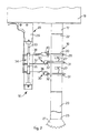
- FIG. 2 is an enlargement of a detail in FIG. 1 ;
- FIG. 3 is a lateral view of an enlarged detail of the measuring device in FIG. 1 .
- a measuring device denoted generally with all its components, main and accessory, with the reference number 10 , is used in a drilling apparatus 11 , only partly shown, in order to obtain the necessary reference signals to obtain seismic measurements during the drilling operation in a ground 13 .
- the apparatus 11 comprises a drilling tower 14 and a mobile drilling unit 15 , which can be raised and lowered, for example sliding on guides 39 made on said tower 14 .
- the mobile drilling unit 15 in this case of the so-called top drive type, in turn comprises a movement unit 16 , of a known type, mounted on the drilling tower 14 and able to move the whole mobile drilling unit 15 vertically, a motor 18 , connected to the movement unit 16 , a series of tubular elements or rods 19 comprising a plurality of rods 20 coaxial with each other, a damping device 17 and, at the end, a drilling element, called bit 21 .
- the series of rods 19 comprises an upper end 22 , with which the top drive is associated, mounted coaxial with the shaft of the motor 18 , and a lower end 23 , on which the bit 21 is mounted.
- the motor 18 makes the series of rods 19 , and consequently the bit 21 , rotate, so as to make a hole 24 in the ground 13 .
- the drilling unit 15 is moved downwards, for example to increase the depth of the hole 24 .
- the damper device 17 is for example interposed between the motor 18 and the upper end 22 of the series of rods 19 and allows the latter to move with an axial motion with respect to the motor 18 , so as to absorb the stresses or impacts generated during the drilling operation.
- the comparison of the signals, that is, the vibrations generated by the bit 21 and the pilot signals detected by means of the measuring device 10 allows to separate the signals useful for the seismic measurements with respect to the noises that are generated during the drilling operation.
- the measuring device 10 comprises a guide unit 25 , mounted on the mobile drilling unit 15 , in this case below; a slider 34 , mounted sliding on the guide unit 25 ; a guide disk 26 , keyed onto the series of rods 19 in correspondence with the guide unit 25 ; one or more sensors 27 , in this case two, mounted on the series of rods 19 in order to detect the pilot signals directly on the rods 20 ; two electromagnetic induction feed and transmission devices, denominated EMI devices 30 ; and a detection and feed, and possibly recording, unit 28 , which both supplies electric feed to both the EMI devices 30 and also detects the signals produced by the sensors 27 .
- the sensors 27 in this case are signal transducers which generate an electric signal used without limitations as an analogical and/or digital signal.
- Each EMI device 30 comprises a rotary element, or rotor 31 , mounted solid and coaxial with the series of rods 19 and a rotationally fixed element, or stator 32 , mounted on the guide unit 25 , connected to the detection and feed unit 28 and able to contain, with play, a part of the periphery of the rotor 31 , so as to prevent problems of interference and friction due to mechanical contact between the stator 32 and rotor 31 .
- the rotation of the series of rods 19 causes the rotation of the rotor 31 inside the stator 32 , between which, due to the effect of the electric feed of the stator 32 by the detection and feed, and possibly recording, unit 28 , the phenomenon of electromagnetic induction is generated.
- the electric current supplied through the stator 32 is used both to feed the sensors 27 , for example connected by cable to the rotor 31 , and also to transmit easily to the detection and feed unit 28 the analogical and/or digital signals measured by the sensors 27 themselves.
- the guide unit 25 ( FIGS. 2 and 3 ) comprises a support 29 , advantageously metal, mounted on the mobile drilling unit 15 , and two cylindrical guides 33 , mounted on the support 29 , both parallel to each other and also parallel to the series of rods 19 .
- the slider comprises two sleeves 35 , mounted coaxial and sliding on the corresponding cylindrical guides 33 , and three metal arms 36 , 37 and 38 , attached to both the sleeves 35 and in this case disposed perpendicular to the latter and parallel to each other.
- Each of the first two arms 36 and 37 supports the stator 32 of a corresponding EMI device 30
- the third arm 38 is disposed in correspondence with the guide disk 26 and comprises two connection wheels, of small diameter.
- the latter have their axes of rotation parallel and suitably distanced from each other, so that each wheel 40 contacts a corresponding lower and upper surface of the guide disk 26 and, in use, is made to rotate with an anti-friction function.
- the third arm 38 is connected to the guide disk 26 , making the slider 34 move along the cylindrical guides 33 with a vertical axial motion coordinated to and of the same entity as that of the series of rods 19 ; this consequently allows the stators 32 both to remain always aligned with the corresponding rotors 31 , and also to accommodate with play the peripheral part of the corresponding rotor 31 , whatever the position assumed by the series of rods 19 with respect to the motor 18 , within the limits of constructional tolerance. It is therefore possible, during the entire drilling operation, both to guarantee a constant electric feed to the sensors 27 , and also to transmit the signals detected by the sensors 27 to the detection and feed unit 28 , also when disposed remote with respect to the measuring position.
- the wheels 40 mounted on the third arm 38 may be replaced by two bearings, not shown here, each disposed in contact with a corresponding surface of the guide disk 26 .
Landscapes
- Engineering & Computer Science (AREA)
- Physics & Mathematics (AREA)
- Life Sciences & Earth Sciences (AREA)
- Mining & Mineral Resources (AREA)
- Geology (AREA)
- Geophysics (AREA)
- Environmental & Geological Engineering (AREA)
- Fluid Mechanics (AREA)
- Remote Sensing (AREA)
- Acoustics & Sound (AREA)
- General Life Sciences & Earth Sciences (AREA)
- Geochemistry & Mineralogy (AREA)
- Earth Drilling (AREA)
- Geophysics And Detection Of Objects (AREA)
- Drilling And Boring (AREA)
- Perforating, Stamping-Out Or Severing By Means Other Than Cutting (AREA)
Applications Claiming Priority (4)
| Application Number | Priority Date | Filing Date | Title |
|---|---|---|---|
| ITUD2004A000207 | 2004-11-08 | ||
| ITUD2004A0207 | 2004-11-08 | ||
| IT000207A ITUD20040207A1 (it) | 2004-11-08 | 2004-11-08 | Dispositivo di misura per un'apparecchiatura di perforazione |
| PCT/EP2005/055775 WO2006048455A1 (en) | 2004-11-08 | 2005-11-07 | Measuring device for a drilling apparatus |
Publications (2)
| Publication Number | Publication Date |
|---|---|
| US20070279249A1 US20070279249A1 (en) | 2007-12-06 |
| US8064289B2 true US8064289B2 (en) | 2011-11-22 |
Family
ID=35589552
Family Applications (1)
| Application Number | Title | Priority Date | Filing Date |
|---|---|---|---|
| US11/667,217 Expired - Fee Related US8064289B2 (en) | 2004-11-08 | 2005-11-07 | Measuring device for a drilling apparatus |
Country Status (6)
| Country | Link |
|---|---|
| US (1) | US8064289B2 (it) |
| EP (1) | EP1815105B1 (it) |
| AT (1) | ATE394580T1 (it) |
| DE (1) | DE602005006609D1 (it) |
| IT (1) | ITUD20040207A1 (it) |
| WO (1) | WO2006048455A1 (it) |
Cited By (1)
| Publication number | Priority date | Publication date | Assignee | Title |
|---|---|---|---|---|
| US20100172206A1 (en) * | 2007-05-31 | 2010-07-08 | Jacques Guigne | Enhanced wide area seabed analysis |
Citations (8)
| Publication number | Priority date | Publication date | Assignee | Title |
|---|---|---|---|---|
| US3993974A (en) | 1974-06-03 | 1976-11-23 | Senturion Sciences, Inc. | Seismic method for determining the position of the bit on a drill stem in a deep borehole |
| US5242025A (en) * | 1992-06-30 | 1993-09-07 | Union Oil Company Of California | Guided oscillatory well path drilling by seismic imaging |
| US5565860A (en) | 1994-06-28 | 1996-10-15 | Radic Co., Ltd. | Underground information collecting apparatus having a noise cancel function |
| US6094401A (en) * | 1996-03-12 | 2000-07-25 | Schlumberger Technology Corporation | Inverse vertical seismic profiling using a measurement while drilling tool as a seismic source |
| US6237404B1 (en) * | 1998-02-27 | 2001-05-29 | Schlumberger Technology Corporation | Apparatus and method for determining a drilling mode to optimize formation evaluation measurements |
| WO2003036042A1 (en) | 2001-10-19 | 2003-05-01 | Schlumberger Technology B.V. | Method of monitoring a drilling path |
| US20060131099A1 (en) * | 2002-09-26 | 2006-06-22 | Patrick Meynier | Device for seismic emission in an underground formation and method for implementing same |
| US20070143027A1 (en) * | 2002-03-22 | 2007-06-21 | Schlumberger Technology Corporation | Method and Apparatus for Borehole Sensing |
-
2004
- 2004-11-08 IT IT000207A patent/ITUD20040207A1/it unknown
-
2005
- 2005-11-07 WO PCT/EP2005/055775 patent/WO2006048455A1/en not_active Ceased
- 2005-11-07 EP EP05813336A patent/EP1815105B1/en not_active Expired - Lifetime
- 2005-11-07 DE DE602005006609T patent/DE602005006609D1/de not_active Expired - Lifetime
- 2005-11-07 AT AT05813336T patent/ATE394580T1/de not_active IP Right Cessation
- 2005-11-07 US US11/667,217 patent/US8064289B2/en not_active Expired - Fee Related
Patent Citations (8)
| Publication number | Priority date | Publication date | Assignee | Title |
|---|---|---|---|---|
| US3993974A (en) | 1974-06-03 | 1976-11-23 | Senturion Sciences, Inc. | Seismic method for determining the position of the bit on a drill stem in a deep borehole |
| US5242025A (en) * | 1992-06-30 | 1993-09-07 | Union Oil Company Of California | Guided oscillatory well path drilling by seismic imaging |
| US5565860A (en) | 1994-06-28 | 1996-10-15 | Radic Co., Ltd. | Underground information collecting apparatus having a noise cancel function |
| US6094401A (en) * | 1996-03-12 | 2000-07-25 | Schlumberger Technology Corporation | Inverse vertical seismic profiling using a measurement while drilling tool as a seismic source |
| US6237404B1 (en) * | 1998-02-27 | 2001-05-29 | Schlumberger Technology Corporation | Apparatus and method for determining a drilling mode to optimize formation evaluation measurements |
| WO2003036042A1 (en) | 2001-10-19 | 2003-05-01 | Schlumberger Technology B.V. | Method of monitoring a drilling path |
| US20070143027A1 (en) * | 2002-03-22 | 2007-06-21 | Schlumberger Technology Corporation | Method and Apparatus for Borehole Sensing |
| US20060131099A1 (en) * | 2002-09-26 | 2006-06-22 | Patrick Meynier | Device for seismic emission in an underground formation and method for implementing same |
Non-Patent Citations (1)
| Title |
|---|
| International Search Report from corresponding International Application No. PCT/EP2005/055775, mailed Feb. 1, 2006. |
Cited By (2)
| Publication number | Priority date | Publication date | Assignee | Title |
|---|---|---|---|---|
| US20100172206A1 (en) * | 2007-05-31 | 2010-07-08 | Jacques Guigne | Enhanced wide area seabed analysis |
| US8547781B2 (en) * | 2007-05-31 | 2013-10-01 | Pangeo Subsea, Inc. | Enhanced wide area seabed analysis |
Also Published As
| Publication number | Publication date |
|---|---|
| ITUD20040207A1 (it) | 2005-02-08 |
| US20070279249A1 (en) | 2007-12-06 |
| EP1815105A1 (en) | 2007-08-08 |
| ATE394580T1 (de) | 2008-05-15 |
| WO2006048455A1 (en) | 2006-05-11 |
| EP1815105B1 (en) | 2008-05-07 |
| DE602005006609D1 (de) | 2008-06-19 |
Similar Documents
| Publication | Publication Date | Title |
|---|---|---|
| US10550640B2 (en) | Intelligent top drive for drilling rigs | |
| CA2545377C (en) | Downhole motor with a continuous conductive path | |
| CN109814098B (zh) | 一种用于煤矿探测的具有调节功能的单孔地质雷达仪 | |
| US11913335B2 (en) | Apparatus and method for drilling a wellbore with a rotary steerable system | |
| CA2616909A1 (en) | Surface communication apparatus and method for use with drill string telemetry | |
| CA2576448A1 (en) | Method and apparatus for drilling and servicing subterranean wells with rotating coiled tubing | |
| US20100071910A1 (en) | Method and system for using wellbore instruments with a wired pipe string | |
| CN104074510A (zh) | 一种钻机用深度检测装置 | |
| CN106895771B (zh) | 一种煤矿液压支架排列直线度检测装置 | |
| CN106988727A (zh) | 一种钻井用定向传感器 | |
| CN108760284A (zh) | 一种多功能转子实验测试装置 | |
| US8064289B2 (en) | Measuring device for a drilling apparatus | |
| CN111854710A (zh) | 一种地下管线测绘方法 | |
| CN115685234B (zh) | 一种盾构机用滚刀性能监测装置 | |
| CN111236958B (zh) | 一种带有工作面状态及滚刀运行状况监测的滚压破岩钻头 | |
| CN110529102B (zh) | 一种石油钻井定向mwd井下探管 | |
| CN203978422U (zh) | 一种钻机用深度检测装置 | |
| CN208505602U (zh) | 一种多功能转子实验测试装置 | |
| JP3054195B2 (ja) | ボーリングマストのスイベルの移動測定装置 | |
| CN206638140U (zh) | 一种煤矿液压支架排列直线度检测装置 | |
| CN116673347A (zh) | 一种间隙可控式白铜金属材料压延设备 | |
| CN210152638U (zh) | 重力式钻芯孔测斜仪 | |
| CN108387218A (zh) | 一种可实现360度范围角度自调整的测斜仪与操作方法 | |
| CN113982564A (zh) | 井深伽马测深跟踪仪 | |
| CN220491048U (zh) | 一种用于矿山监测的冲击回波仪 |
Legal Events
| Date | Code | Title | Description |
|---|---|---|---|
| AS | Assignment |
Owner name: ISTITUTO NAZIONALE DI OCEANOGRAFIA E DI GEOFISICA Free format text: ASSIGNMENT OF ASSIGNORS INTEREST;ASSIGNORS:POLETTO, FLAVIO;SCHLEIFER, ANDREA;DORDOLO, GIULIANO;REEL/FRAME:019307/0374 Effective date: 20070427 |
|
| REMI | Maintenance fee reminder mailed | ||
| LAPS | Lapse for failure to pay maintenance fees | ||
| STCH | Information on status: patent discontinuation |
Free format text: PATENT EXPIRED DUE TO NONPAYMENT OF MAINTENANCE FEES UNDER 37 CFR 1.362 |
|
| STCH | Information on status: patent discontinuation |
Free format text: PATENT EXPIRED DUE TO NONPAYMENT OF MAINTENANCE FEES UNDER 37 CFR 1.362 |
|
| FP | Lapsed due to failure to pay maintenance fee |
Effective date: 20151122 |