US8070142B2 - Downcomer distributor - Google Patents
Downcomer distributor Download PDFInfo
- Publication number
- US8070142B2 US8070142B2 US12/018,882 US1888208A US8070142B2 US 8070142 B2 US8070142 B2 US 8070142B2 US 1888208 A US1888208 A US 1888208A US 8070142 B2 US8070142 B2 US 8070142B2
- Authority
- US
- United States
- Prior art keywords
- tray
- downcomer
- distributor
- deck
- discharge ports
- Prior art date
- Legal status (The legal status is an assumption and is not a legal conclusion. Google has not performed a legal analysis and makes no representation as to the accuracy of the status listed.)
- Active, expires
Links
- 239000007788 liquid Substances 0.000 claims abstract description 69
- 238000001311 chemical methods and process Methods 0.000 claims abstract description 14
- 238000009826 distribution Methods 0.000 claims description 27
- 239000012530 fluid Substances 0.000 claims description 3
- 230000008901 benefit Effects 0.000 abstract description 5
- 230000000694 effects Effects 0.000 abstract description 3
- 238000012546 transfer Methods 0.000 abstract description 2
- 238000013461 design Methods 0.000 description 14
- 238000002474 experimental method Methods 0.000 description 9
- 238000004821 distillation Methods 0.000 description 8
- XLYOFNOQVPJJNP-UHFFFAOYSA-N water Substances O XLYOFNOQVPJJNP-UHFFFAOYSA-N 0.000 description 8
- 238000000034 method Methods 0.000 description 5
- 238000002347 injection Methods 0.000 description 4
- 239000007924 injection Substances 0.000 description 4
- 238000012986 modification Methods 0.000 description 4
- 230000004048 modification Effects 0.000 description 4
- 238000000926 separation method Methods 0.000 description 3
- QVGXLLKOCUKJST-UHFFFAOYSA-N atomic oxygen Chemical compound [O] QVGXLLKOCUKJST-UHFFFAOYSA-N 0.000 description 2
- 230000001010 compromised effect Effects 0.000 description 2
- 238000003795 desorption Methods 0.000 description 2
- 239000007789 gas Substances 0.000 description 2
- 238000010348 incorporation Methods 0.000 description 2
- 239000001301 oxygen Substances 0.000 description 2
- 229910052760 oxygen Inorganic materials 0.000 description 2
- 230000008569 process Effects 0.000 description 2
- 238000010521 absorption reaction Methods 0.000 description 1
- 238000000429 assembly Methods 0.000 description 1
- 230000000712 assembly Effects 0.000 description 1
- 230000003190 augmentative effect Effects 0.000 description 1
- 230000009286 beneficial effect Effects 0.000 description 1
- 230000015572 biosynthetic process Effects 0.000 description 1
- 238000003889 chemical engineering Methods 0.000 description 1
- 238000006243 chemical reaction Methods 0.000 description 1
- 238000010276 construction Methods 0.000 description 1
- 230000007423 decrease Effects 0.000 description 1
- 238000000605 extraction Methods 0.000 description 1
- 238000004519 manufacturing process Methods 0.000 description 1
- 239000000463 material Substances 0.000 description 1
- 238000005259 measurement Methods 0.000 description 1
- 238000002156 mixing Methods 0.000 description 1
- 239000000203 mixture Substances 0.000 description 1
- 230000000750 progressive effect Effects 0.000 description 1
- 230000009467 reduction Effects 0.000 description 1
- 238000003892 spreading Methods 0.000 description 1
- 230000007480 spreading Effects 0.000 description 1
- 230000009897 systematic effect Effects 0.000 description 1
- 238000012360 testing method Methods 0.000 description 1
- 238000003466 welding Methods 0.000 description 1
Images


Classifications
-
- B—PERFORMING OPERATIONS; TRANSPORTING
- B01—PHYSICAL OR CHEMICAL PROCESSES OR APPARATUS IN GENERAL
- B01D—SEPARATION
- B01D3/00—Distillation or related exchange processes in which liquids are contacted with gaseous media, e.g. stripping
- B01D3/14—Fractional distillation or use of a fractionation or rectification column
- B01D3/16—Fractionating columns in which vapour bubbles through liquid
- B01D3/18—Fractionating columns in which vapour bubbles through liquid with horizontal bubble plates
- B01D3/20—Bubble caps; Risers for vapour; Discharge pipes for liquid
-
- B—PERFORMING OPERATIONS; TRANSPORTING
- B01—PHYSICAL OR CHEMICAL PROCESSES OR APPARATUS IN GENERAL
- B01D—SEPARATION
- B01D3/00—Distillation or related exchange processes in which liquids are contacted with gaseous media, e.g. stripping
- B01D3/14—Fractional distillation or use of a fractionation or rectification column
- B01D3/32—Other features of fractionating columns ; Constructional details of fractionating columns not provided for in groups B01D3/16 - B01D3/30
- B01D3/324—Tray constructions
-
- B—PERFORMING OPERATIONS; TRANSPORTING
- B01—PHYSICAL OR CHEMICAL PROCESSES OR APPARATUS IN GENERAL
- B01D—SEPARATION
- B01D3/00—Distillation or related exchange processes in which liquids are contacted with gaseous media, e.g. stripping
- B01D3/008—Liquid distribution
-
- B—PERFORMING OPERATIONS; TRANSPORTING
- B01—PHYSICAL OR CHEMICAL PROCESSES OR APPARATUS IN GENERAL
- B01D—SEPARATION
- B01D3/00—Distillation or related exchange processes in which liquids are contacted with gaseous media, e.g. stripping
- B01D3/14—Fractional distillation or use of a fractionation or rectification column
- B01D3/32—Other features of fractionating columns ; Constructional details of fractionating columns not provided for in groups B01D3/16 - B01D3/30
Definitions
- the present invention relates to distillation trays for use in chemical process towers.
- tray designs are known for gas-liquid contactors used in processes including reactions and separations. In each design, trays are situated within the towers for contact between the components of mixtures within the towers.
- tray designs are known, as described by, for example, Philip C. Wankat in “Equilibrium Staged Separations” published by Elsevier (1988), C. Judson King in “Separation Processes” published by McGraw-Hill Book Company (2 nd edition, 1980), Henry Z. Kister in “Distillation Design” published by McGraw-Hill, Inc. (1992), and Johann G. Stichlmair and James R. Fair in “Distillation: Principles and Practice” published by Wiley-VCH (1998). It is also known that the downcomer layout pattern affects tray efficiency, as described by Wijn, E. F. in “The effect of downcomer layout pattern on tray efficiency” published in The Chemical Engineering Journal, vol. 63, pages 167-180 (1996).
- Chemical process towers are designed for performance of a variety of processes, as illustrated in commercial literature available from tower manufacturers such as “Trays for Distillation, Absorption, Stripping and Extraction” published by UOP.
- the tray assembly described herein relates to an improved design for trays within a chemical process tower.
- the downcomers of the trays include a distributor subtending therebelow.
- the distributor includes a series of discharge ports and associated flanges.
- the discharge ports are sized so as to control the rate of liquid flow at different positions across the distributor.
- the flanges are aligned individually to direct the liquid flow across different areas of the tray deck immediately below.
- the discharge ports and liquid flow directing flanges effect more even liquid flow across the surface of the tray immediately below, thereby avoiding the formation of stagnant regions. The net result is that there is higher tray capacity and efficiency when compared with prior art trays.
- the tray includes a tray deck, an inlet distribution area, and a downcomer.
- the downcomer includes an angled portion, the angled portion extending downward relative to the tray deck at an angle between 0 degrees and 90 degrees, and terminating in a distributor region.
- the distributor region has a series of discharge ports formed in the angled portion, each discharge port having more than one side. At least one side has a flange that extends below the discharge port, such that fluid flowing down the downcomer is distributed as it flows through the distributor region.
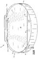
- FIG. 1 is a cut-away perspective view of a portion of a tower having a tray fitted therein, showing at an angle the face of a downcomer having a distributor.
- FIG. 2 is a cut-away perspective view of a portion of a tower having a tray fitted therein shown in FIG. 1 , showing a back view of the downcomer and distributor.
- FIG. 3 is a close-up view of the face of a downcomer and distributor shown in FIGS. 1 and 2 .
- FIG. 4 is a top view of a portion of a tray, showing a combination of the tray deck, downcomer and distributor.
- FIG. 5A through 5E is a series of perspective drawings showing the pattern of flow over the deck of a tray having a straight downcomer at 0 seconds, 10 seconds, 20 seconds, 40 seconds, and 60 seconds after injection of the dye into the liquid at the inlet, respectively.
- FIG. 6A through 6E is a series of perspective drawings showing the pattern of flow over the deck of a tray having a sweptback downcomer at 0 seconds, 10 seconds, 20 seconds, 40 seconds, and 60 seconds after injection of the dye into the liquid at the inlet, respectively.
- FIG. 7A through 7E is a series of perspective drawings showing the pattern of flow over the deck of a tray having a downcomer and a distributor at 0 seconds, 10 seconds, 20 seconds, 40 seconds, and 60 seconds after injection of the dye into the liquid at the inlet, respectively.
- FIG. 8 is a cut-away perspective view of a counter-flow apparatus having the tray shown in FIG. 1 through 3 , the tower having: Tower ID, 1,200 mm; Tray spacing, 600 mm; No, of Pass, 1; DC Area, 6.7% TA; Weir Height, 38 mm; Floating Valve Units; number of Tray Valve Units: 131 ( ⁇ 12% open area).
- FIG. 9A through 9D are plots comparing oxygen desorption tray efficiencies for the tested tray as a function of F-factor using a 1.2 m internal diameter column air-water tower as shown in FIG. 8 , a segmented tray having a conventional downcomer and a tray having a downcomer and a distributor
- the downcomer of the tray includes a distributor.
- the downcomer distributor has a series of discharge ports and liquid flow directing flanges, the combination of which provides a relatively even flow across the tray immediately below the downcomer. This reduces the maldistribution present in other designs, which in turn improves the efficiency of gas-liquid contact on the tray.
- a tray assembly generally identified by reference numeral 10 , will now be described with reference to FIG. 1 through FIG. 7 .
- a tray assembly 10 for gas/liquid contact is installed in a chemical process tower, shown in cut-away and identified by reference numeral 12 , having walls 14 with an inner surface 16 , within which tray assemblies 10 can be affixed.
- Tray 10 has a tray deck 20 , which may comprise either one or several portions, and at least one first downcomer 22 at an edge 24 of deck 20 .
- tray 10 has an outlet weir 26 to maintain a depth of a liquid 76 (shown in FIG. 5 through 7 ) above deck 20 , and, optionally, an inlet weir 27 (shown in FIG. 5 through 7 ) adjacent an inlet distribution area 30 .
- a plurality of trays 10 are situated within tower 12 . Trays 10 are mutually oriented so that an outlet downcomer 22 of an upper tray 10 is situated above inlet receiving area 30 of the immediately lower tray 10 .
- FIG. 1 through 4 illustrate an embodiment of tray 10 having an unportioned tray deck 20 extending from inlet distribution area 30 to edge 24 and exit downcomer 22 . It will be recognized that the architecture of tray 10 may include a plurality of downcomers 22 interposed between a plurality of portions of deck 20 .
- downcomer 22 is adjacent inner surface 16 of walls 14 of tower 12 , and is bounded on one side by a portion 28 of inner surface 16 of walls 14 , and on the other side by a downcomer wall 32 .
- Downcomer wall 32 extends downward across the length of edge 24 of deck 20 toward inlet receiving area 30 of another deck 20 immediately below. There is a gap 34 between a bottom edge 36 (downcomer bottom chord) of downcomer wall 32 and the lower tray deck 20 , gap 34 extending along all or the majority of the length of first downcomer wall 32 .
- downcomer wall 32 has a first portion 32 A, a second portion 32 B, and a third portion that is a distributor 32 C.
- First portion 32 A is affixed to deck 20 at edge 24 .
- a top 40 of portion 32 B is affixed to a bottom 42 of portion 32 A.
- distributor 32 C comprises a lower section of the same component part as second portion 32 B that is cut and shaped to form the shape of distributor 32 C.
- Attachments between deck 20 , first portion 32 A and second portion 32 B are shown as screws or rivets 44 , augmented by flanges 46 . It will be recognized that alternative methods of construction may be used, such as welding together of portions, and that individual portions 32 A, 32 B and 32 C and combinations thereof may be constructed from one or more component materials.
- distributor 32 C has a substantially vertical first portion 32 A of downcomer wall 32 . It has been found through experiment that the performance of tray 10 is improved when second portion 32 B is sloped in a direction away from deck 20 and toward portion 28 of walls 14 . For ease of manufacture and for good performance of tray 10 , distributor 32 C may be constructed and oriented as an extension at the same angle as second portion 32 B, however the angle of distributor 32 C may be different from that of second portion 32 B.
- distributor 32 C has a series of discharge ports 50 .
- Discharge ports 50 are V-shaped notches, and have a right-angled apex 52 . It will be recognized that V-shaped discharge ports 50 may have a different apex angle 54 , and that discharge ports 50 may have different shapes without diverging from the principles and purposes of the present invention.
- Discharge ports 50 have an outer lower edge 56 toward the ends 58 of distributor 32 C, and an inner lower edge 60 toward the center 62 of distributor 32 C.
- a flange 64 extends downward from inner lower edge 60 of discharge ports 50 .
- each discharge port 50 and the different orientations of each flange 64 are such that the volumetric liquid flow is controlled and directed so that the area distribution of the volumetric liquid flow across tray deck 20 is very even.
- the angles of flanges 64 and the size of gap 34 which is small when the bottom 36 of flanges 64 is proximate to deck 20 of the other tray 10 immediately below, are such that liquid flowing downward over distributor 32 C is then directed in different directions across the deck 20 immediately below inlet downcomer 22 .
- outer discharge ports 66 and associated flanges 64 direct liquid flow across portions of deck 20 adjacent walls 14 .
- Inner discharge ports 68 and associated flanges 64 direct liquid flow across central portions of deck 20 .
- Intermediate discharge ports and flanges direct liquid flow in directions intermediate between the inner and outer flows. As will be shown in FIG. 7 , there is lateral mixing between the directed liquid flows.
- FIG. 4 shows the geometry for one embodiment of distributor 32 C of tray 10 , shown experimentally to be effective for generating even distribution of liquid flow across a tray deck immediately below distributor 32 C.
- discharge ports 50 are V-notches of which the angle 54 at each apex 52 is the same and is a right-angle.
- V-notch discharge port apex angle 54 may have a value ranging from about 60 degrees to about 120 degrees, with an angle of 90 degrees being shown.
- the outer lower edge 56 of each discharge port 50 has the same length L 1 , such as 112 mm. As shown the length of the straight central portion 61 of distributor 32 C is also L 1 .
- FIG. 5A through 7E are drawings taken during progress of a series of experiments performed using two prior art tray designs, a tray having a straight downcomer 70 ( FIG. 5A through 5E ) and a tray having a swept-back downcomer 72 ( FIG. 6A through 6E ), and one embodiment of tray 10 of the present invention ( FIG. 7A through 7E ).
- the experimental data clearly show the benefit of use of trays 10 of the present invention.
- the liquid flow rate was the same and continuous, and the internal diameter of the open tower 12 holding the respective tray was the same large diameter.
- the large size of the tower (17 feet internal diameter) can be seen by comparison with the sizes of operators 90 performing the experiments.
- FIG. 5A through 5E show drawings of the experiment using tray 70 , having a straight downcomer.
- the experiment was filmed;
- FIG. 5A through 5E are a sequence of still photographs at the time of injection of dye 74 ( FIG. 5A ), then after 10, 20, 40 and 60 seconds sequentially ( FIGS. 5B through 5 E).
- Liquid 76 containing dye 74 initially traveled in a direct path from inlet receiving area 30 below inlet 78 toward downcomer 22 . After 20 seconds the liquid flow containing dye 74 reached downcomer 22 and also began to flow backward toward inlet 78 along the walls 14 of tower 12 .
- Kister in FIG.
- FIG. 6A through 6E show still drawings taken at the same intervals as for FIG. 5A through 7E , for an experiment using tray 72 having a sweptback downcomer.
- flow of liquid 76 containing dye 74 was initially directed primarily in a direction from inlet receiving area 30 below inlet 78 toward downcomer 22 .
- the flow of the portion of liquid 76 containing dye 74 from the ends of inlet receiving area 30 appeared to travel more slowly than that from the center of inlet 78 .
- tray 10 showed much better distribution of liquid flow, as illustrated in still drawings FIG. 7A through 7E taken at the same intervals and under the same experimental conditions as those shown in FIG. 5A through 6E .
- inlet receiving area 30 is below inlet 78 that is a downcomer having a downcomer wall 32 comprising first portion 32 A, second portion 32 B and distributor 32 C as shown in FIG. 1 through 3 .
- FIG. 7B through 7D show that liquid 76 containing dye 74 flows in all angular directions from inlet 78 toward outlet downcomer 22 , thus is more evenly distributed so as to flow across all parts of deck 20 . There is a much reduced amount of backflow.
- Performance of one tray using an inlet downcomer 22 having distributor 32 C of the present invention was compared with that of the same tray having a segmental downcomer according to the prior art using an air-water simulator 100 of a counter-flow apparatus illustrated in FIG. 8 .
- the performances of the trays were measured using apparatus with the parameters: Tower ID, 1,200 mm; Tray Spacing, 600 mm; No. of Pass, 1; DC Area, 6.7% TA; Weir Height, 38 mm; number of Valve Units: 131 ( ⁇ 12% open area).
- Air-water simulator 100 comprises a tower 112 having one tray 10 and a receiving tray 110 therebelow.
- Water 102 following serpentine path 104 , was fed via one downcomer 22 to tray 10 , crossed deck 20 , then exited tray 10 via another downcomer 122 to receiving tray 110 , from which it flowed out of tower 112 .
- the following tests were performed with a downcomer wall of downcomer 32 being either downcomer wall 32 having distributor 32 C according to the present invention or a conventional downcomer wall.
- Air 106 following a path illustrated by arrows 108 , was fed in countercurrent manner through tower 112 , and bubbled through water 102 flowing across deck 20 .
- FIG. 9A through 9D show four plots comparing oxygen desorption tray efficiencies as a function of F-factor when using the air-water simulator shown in FIG. 8 , for performances of a segmental tray having a conventional downcomer and a tray having a downcomer and a distributor 32 C according to the present invention, at three different flow rates, 120 gpm ( FIG. 9A ), 180 gpm ( FIG. 9B ), and 240 gpm ( FIG. 9C ).
- FIG. 9D compares data for both trays at all three flow rates. At each flow rate the performance of the tray and distributor of the present invention was superior to that of the tray having a segmental downcomer. Further, the performance of tray 10 and distributor 32 C according to the present invention was similar over the range of flow rates.
- the tray design allows for a higher capacity and efficiency, in which the distribution of volumetric liquid flow across the tray deck is essentially similar for all paths along which that liquid flows.
Landscapes
- Chemical & Material Sciences (AREA)
- Chemical Kinetics & Catalysis (AREA)
- Vaporization, Distillation, Condensation, Sublimation, And Cold Traps (AREA)
- Physical Or Chemical Processes And Apparatus (AREA)
Priority Applications (8)
| Application Number | Priority Date | Filing Date | Title |
|---|---|---|---|
| US12/018,882 US8070142B2 (en) | 2008-01-24 | 2008-01-24 | Downcomer distributor |
| KR1020107018682A KR101597165B1 (ko) | 2008-01-24 | 2009-01-23 | 다운커머 분배기 |
| MYPI2010003498A MY159727A (en) | 2008-01-24 | 2009-01-23 | Downcomer distributor |
| CN200980106915.8A CN101970071B (zh) | 2008-01-24 | 2009-01-23 | 降液管分配器 |
| BRPI0907638A BRPI0907638B1 (pt) | 2008-01-24 | 2009-01-23 | bandeja para uma coluna de contato de gás líquido e coluna de contato de gás/líquido |
| EP09704602.3A EP2242554B1 (fr) | 2008-01-24 | 2009-01-23 | Distributeur de descente |
| PCT/US2009/031774 WO2009094503A2 (fr) | 2008-01-24 | 2009-01-23 | Distributeur de descente |
| ZA2010/05496A ZA201005496B (en) | 2008-01-24 | 2010-08-02 | Downcomer distributor |
Applications Claiming Priority (1)
| Application Number | Priority Date | Filing Date | Title |
|---|---|---|---|
| US12/018,882 US8070142B2 (en) | 2008-01-24 | 2008-01-24 | Downcomer distributor |
Publications (2)
| Publication Number | Publication Date |
|---|---|
| US20090189301A1 US20090189301A1 (en) | 2009-07-30 |
| US8070142B2 true US8070142B2 (en) | 2011-12-06 |
Family
ID=40898391
Family Applications (1)
| Application Number | Title | Priority Date | Filing Date |
|---|---|---|---|
| US12/018,882 Active 2030-10-07 US8070142B2 (en) | 2008-01-24 | 2008-01-24 | Downcomer distributor |
Country Status (8)
| Country | Link |
|---|---|
| US (1) | US8070142B2 (fr) |
| EP (1) | EP2242554B1 (fr) |
| KR (1) | KR101597165B1 (fr) |
| CN (1) | CN101970071B (fr) |
| BR (1) | BRPI0907638B1 (fr) |
| MY (1) | MY159727A (fr) |
| WO (1) | WO2009094503A2 (fr) |
| ZA (1) | ZA201005496B (fr) |
Cited By (1)
| Publication number | Priority date | Publication date | Assignee | Title |
|---|---|---|---|---|
| EP3260180A1 (fr) | 2016-06-20 | 2017-12-27 | AMT International, Inc. | Ensemble plateau pour colonne de contact gaz/liquide |
Families Citing this family (3)
| Publication number | Priority date | Publication date | Assignee | Title |
|---|---|---|---|---|
| US8944418B2 (en) * | 2011-05-16 | 2015-02-03 | Koch-Glitsch, Lp | Use of downcomer beam to support adjacent cross flow trays within a mass transfer column and process involving same |
| WO2013138185A1 (fr) * | 2012-03-12 | 2013-09-19 | Koch-Glitsch, Lp | Plateau à une passe et système de support destinés à être utilisés dans une colonne de transfert de masse |
| CN115501631B (zh) * | 2022-09-19 | 2023-06-20 | 山东华仙浩森生物科技有限公司 | 用于甜叶菊成分提取的蒸馏釜 |
Citations (53)
| Publication number | Priority date | Publication date | Assignee | Title |
|---|---|---|---|---|
| US3218048A (en) | 1960-09-14 | 1965-11-16 | Gen Cable Corp | Packing for fractionating column and the like |
| GB1065554A (en) | 1963-04-08 | 1967-04-19 | Separation Processes Corp | Improvements in liquid-vapour contact apparatus |
| US3450393A (en) | 1964-07-10 | 1969-06-17 | Carl Georg Munters | Gas and liquid contact apparatus |
| US3647192A (en) | 1969-03-31 | 1972-03-07 | Shell Oil Co | Gas-liquid contacting tray |
| US3729179A (en) | 1970-09-23 | 1973-04-24 | Fractionation Res Inc | Apparatus for liquid and vapor or gas mass transfer |
| US3747905A (en) | 1970-11-10 | 1973-07-24 | Pantaleoni N | Contact apparatus and method |
| US3887665A (en) | 1973-04-20 | 1975-06-03 | Thomas William Mix | Vapor-liquid contacting |
| US3959419A (en) | 1973-09-06 | 1976-05-25 | Fritz W. Glitsch & Sons, Inc. | Vapor-liquid contact method |
| US4105723A (en) | 1976-05-24 | 1978-08-08 | Merix Corporation | Vapor-liquid contacting |
| US4274923A (en) | 1979-02-22 | 1981-06-23 | Republic Steel Corporation | Air pollution control method and apparatus for the extrusion and quenching of coke |
| US4300918A (en) | 1978-05-08 | 1981-11-17 | Parmatic Filter Corporation | Method for removing moisture particles |
| US4528068A (en) | 1984-03-22 | 1985-07-09 | Exxon Research And Engineering Co. | Tray apparatus for deasphalting and extraction |
| US4597916A (en) | 1983-06-21 | 1986-07-01 | Glitsch, Inc. | Method of and apparatus for intermediate lamella vapor liquid contact |
| US4603022A (en) | 1978-08-15 | 1986-07-29 | Mitsubishi Jukogyo Kabushiki Kaisha | Gas-liquid contactor |
| US4604247A (en) | 1983-06-21 | 1986-08-05 | Glitsch, Inc. | Tower packing material and method |
| EP0250020A2 (fr) | 1986-06-20 | 1987-12-23 | DLC S.r.L. | Eléments de toit autoportants, préfabriqués en béton, pour la construction d'édifices |
| US4818346A (en) | 1986-05-07 | 1989-04-04 | Shell Oil Company | Vertical distillation column with a de-entrainment device |
| US4842778A (en) | 1985-12-23 | 1989-06-27 | Glitsch, Inc. | Apparatus for flow distribution in packed towers |
| US4950430A (en) | 1986-12-01 | 1990-08-21 | Glitsch, Inc. | Structured tower packing |
| US4954294A (en) | 1989-08-11 | 1990-09-04 | Shell Oil Company | Vapor/liquid contact apparatus |
| US5139544A (en) | 1990-10-22 | 1992-08-18 | Koch Engineering Company, Inc. | Gas-liquid contact column with improved mist eliminator and method |
| US5164125A (en) | 1989-03-08 | 1992-11-17 | Glitsch, Inc. | Method and apparatus for downcomer-tray operation |
| US5192466A (en) | 1991-10-09 | 1993-03-09 | Glitsch, Inc. | Method of and apparatus for flow promotion |
| US5213719A (en) | 1992-09-28 | 1993-05-25 | Chuang Karl T | Gas-liquid contacting device |
| US5244604A (en) | 1992-04-02 | 1993-09-14 | Uop | Packing-enhanced baffled downcomer fractionation tray |
| US5262094A (en) | 1990-05-25 | 1993-11-16 | Uop | Fractionation tray having packing immediately below tray deck |
| US5269976A (en) | 1991-11-14 | 1993-12-14 | The Boc Group, Plc | Liquid-vapour contact columns |
| US5277847A (en) | 1989-03-08 | 1994-01-11 | Glitsch, Inc. | Method and apparatus for catalyst-downcomer-tray operation |
| US5366666A (en) | 1990-05-25 | 1994-11-22 | Uop | Multiple downcomer fractionation tray having packing between downcomers |
| US5439510A (en) | 1994-01-21 | 1995-08-08 | Beco Engineering Company | High-velocity, high-capacity mist eliminator assembly and method |
| US5453222A (en) | 1994-09-15 | 1995-09-26 | Glitsch, Inc. | Contact tray apparatus and method |
| US5454989A (en) | 1994-03-23 | 1995-10-03 | Nutter; Dale E. | Vapor-liquid contact apparatus |
| US5554329A (en) | 1993-12-16 | 1996-09-10 | Uop | Fractionation tray formed by triangular downcomer modules |
| US5707563A (en) | 1993-12-16 | 1998-01-13 | Uop | V-module fractionation tray |
| US5762668A (en) | 1996-07-24 | 1998-06-09 | Glitsch, Inc. | Apparatus and method for deentrainment in a chemical process tower |
| US5837105A (en) | 1997-04-07 | 1998-11-17 | Mobil Oil Corporation | Co-current contacting separation tray design and methods for using same |
| US5972171A (en) | 1997-04-08 | 1999-10-26 | Mobil Oil Corporation | De-entrainment tray and method of operation |
| US5975504A (en) | 1997-03-12 | 1999-11-02 | Uop Llc | Closely-spaced high capacity fractionation trays |
| US6003847A (en) * | 1996-10-30 | 1999-12-21 | Koch Enterprises, Inc. | Downcomer for chemical process tower |
| US6029956A (en) | 1998-02-06 | 2000-02-29 | Foster Wheeler Usa Corporation | Predominantly liquid filled vapor-liquid chemical reactor |
| US6053484A (en) | 1997-09-05 | 2000-04-25 | Koch-Glitsch, Inc. | Downcomers for vapor-liquid contact trays |
| US6059934A (en) | 1997-04-07 | 2000-05-09 | Mobil Oil Corporation | Co-current contacting separation tray design and methods for using same |
| US6076813A (en) | 1997-05-12 | 2000-06-20 | Koch-Glitsch, Inc. | Vapor liquid contact tray with two-stage downcomer |
| US6287367B1 (en) | 1998-05-19 | 2001-09-11 | Mobil Oil Corporation | High-capacity vapor/liquid contacting device |
| US6371455B1 (en) | 2001-01-05 | 2002-04-16 | Adam T. Lee | Gas/liquid contacting apparatus |
| US6588735B2 (en) | 2000-02-16 | 2003-07-08 | Shell Oil Company | Gas-liquid tray |
| US6746003B2 (en) * | 2002-08-26 | 2004-06-08 | Amt International, Inc. | Gas-liquid contacting apparatus |
| US6817596B2 (en) | 2001-12-05 | 2004-11-16 | Sulzer Chemtech Ag | Tray column |
| US6948705B2 (en) * | 2003-10-07 | 2005-09-27 | Amt International, Inc. | Gas/liquid contacting apparatus |
| US20060169573A1 (en) * | 2005-02-03 | 2006-08-03 | Lee Adam T | Liquid/liquid exchange column |
| US20070145611A1 (en) | 2005-12-23 | 2007-06-28 | Lee Adam T | Gas-liquid contactor baffle |
| US7648128B2 (en) * | 2006-12-22 | 2010-01-19 | Amt International, Inc. | Gas-liquid contact apparatus |
| US7753348B2 (en) * | 2007-01-30 | 2010-07-13 | Amt International, Inc. | Gas-liquid contact apparatus |
Family Cites Families (5)
| Publication number | Priority date | Publication date | Assignee | Title |
|---|---|---|---|---|
| US4159291A (en) * | 1977-08-16 | 1979-06-26 | Union Carbide Corporation | Outlet means for vapor-liquid contacting tray |
| US4956127A (en) * | 1989-03-08 | 1990-09-11 | Glitsch, Inc. | Downcomer-tray assembly and method |
| US5895608A (en) * | 1996-10-30 | 1999-04-20 | Koch Enterprises, Inc. | Downcomer for chemical process tower and method of forming the same |
| US6575438B2 (en) | 2001-06-13 | 2003-06-10 | Sulzer Chemtech Usa, Inc. | Stepped downcomer apparatus and vapor-liquid contact apparatus with same |
| EP1317948B1 (fr) | 2001-12-05 | 2010-08-25 | Sulzer Chemtech AG | Colonne à plateaux |
-
2008
- 2008-01-24 US US12/018,882 patent/US8070142B2/en active Active
-
2009
- 2009-01-23 WO PCT/US2009/031774 patent/WO2009094503A2/fr not_active Ceased
- 2009-01-23 KR KR1020107018682A patent/KR101597165B1/ko not_active Expired - Fee Related
- 2009-01-23 BR BRPI0907638A patent/BRPI0907638B1/pt active IP Right Grant
- 2009-01-23 EP EP09704602.3A patent/EP2242554B1/fr active Active
- 2009-01-23 MY MYPI2010003498A patent/MY159727A/en unknown
- 2009-01-23 CN CN200980106915.8A patent/CN101970071B/zh active Active
-
2010
- 2010-08-02 ZA ZA2010/05496A patent/ZA201005496B/en unknown
Patent Citations (56)
| Publication number | Priority date | Publication date | Assignee | Title |
|---|---|---|---|---|
| US3218048A (en) | 1960-09-14 | 1965-11-16 | Gen Cable Corp | Packing for fractionating column and the like |
| GB1065554A (en) | 1963-04-08 | 1967-04-19 | Separation Processes Corp | Improvements in liquid-vapour contact apparatus |
| US3450393A (en) | 1964-07-10 | 1969-06-17 | Carl Georg Munters | Gas and liquid contact apparatus |
| US3647192A (en) | 1969-03-31 | 1972-03-07 | Shell Oil Co | Gas-liquid contacting tray |
| US3729179A (en) | 1970-09-23 | 1973-04-24 | Fractionation Res Inc | Apparatus for liquid and vapor or gas mass transfer |
| US3747905A (en) | 1970-11-10 | 1973-07-24 | Pantaleoni N | Contact apparatus and method |
| US3887665A (en) | 1973-04-20 | 1975-06-03 | Thomas William Mix | Vapor-liquid contacting |
| US3959419A (en) | 1973-09-06 | 1976-05-25 | Fritz W. Glitsch & Sons, Inc. | Vapor-liquid contact method |
| US4105723A (en) | 1976-05-24 | 1978-08-08 | Merix Corporation | Vapor-liquid contacting |
| US4132761A (en) | 1976-05-24 | 1979-01-02 | Merix Corporation | Gas-liquid contacting |
| US4300918A (en) | 1978-05-08 | 1981-11-17 | Parmatic Filter Corporation | Method for removing moisture particles |
| US4603022A (en) | 1978-08-15 | 1986-07-29 | Mitsubishi Jukogyo Kabushiki Kaisha | Gas-liquid contactor |
| US4274923A (en) | 1979-02-22 | 1981-06-23 | Republic Steel Corporation | Air pollution control method and apparatus for the extrusion and quenching of coke |
| US4597916A (en) | 1983-06-21 | 1986-07-01 | Glitsch, Inc. | Method of and apparatus for intermediate lamella vapor liquid contact |
| US4604247A (en) | 1983-06-21 | 1986-08-05 | Glitsch, Inc. | Tower packing material and method |
| US4528068A (en) | 1984-03-22 | 1985-07-09 | Exxon Research And Engineering Co. | Tray apparatus for deasphalting and extraction |
| US4842778A (en) | 1985-12-23 | 1989-06-27 | Glitsch, Inc. | Apparatus for flow distribution in packed towers |
| US4818346A (en) | 1986-05-07 | 1989-04-04 | Shell Oil Company | Vertical distillation column with a de-entrainment device |
| EP0250020A2 (fr) | 1986-06-20 | 1987-12-23 | DLC S.r.L. | Eléments de toit autoportants, préfabriqués en béton, pour la construction d'édifices |
| US4950430A (en) | 1986-12-01 | 1990-08-21 | Glitsch, Inc. | Structured tower packing |
| US5277848A (en) | 1989-03-08 | 1994-01-11 | Glitsch, Inc. | Method and apparatus for downcomer tray operation |
| US5164125A (en) | 1989-03-08 | 1992-11-17 | Glitsch, Inc. | Method and apparatus for downcomer-tray operation |
| US5277847A (en) | 1989-03-08 | 1994-01-11 | Glitsch, Inc. | Method and apparatus for catalyst-downcomer-tray operation |
| US4954294A (en) | 1989-08-11 | 1990-09-04 | Shell Oil Company | Vapor/liquid contact apparatus |
| US5366666A (en) | 1990-05-25 | 1994-11-22 | Uop | Multiple downcomer fractionation tray having packing between downcomers |
| US5262094A (en) | 1990-05-25 | 1993-11-16 | Uop | Fractionation tray having packing immediately below tray deck |
| US5139544A (en) | 1990-10-22 | 1992-08-18 | Koch Engineering Company, Inc. | Gas-liquid contact column with improved mist eliminator and method |
| US5192466A (en) | 1991-10-09 | 1993-03-09 | Glitsch, Inc. | Method of and apparatus for flow promotion |
| US5269976A (en) | 1991-11-14 | 1993-12-14 | The Boc Group, Plc | Liquid-vapour contact columns |
| US5244604A (en) | 1992-04-02 | 1993-09-14 | Uop | Packing-enhanced baffled downcomer fractionation tray |
| US5389343A (en) | 1992-08-10 | 1995-02-14 | Glitsch, Inc. | Catalyst assembly and method for chemical process tower |
| US5213719A (en) | 1992-09-28 | 1993-05-25 | Chuang Karl T | Gas-liquid contacting device |
| US5554329A (en) | 1993-12-16 | 1996-09-10 | Uop | Fractionation tray formed by triangular downcomer modules |
| US5707563A (en) | 1993-12-16 | 1998-01-13 | Uop | V-module fractionation tray |
| US5439510A (en) | 1994-01-21 | 1995-08-08 | Beco Engineering Company | High-velocity, high-capacity mist eliminator assembly and method |
| US5454989A (en) | 1994-03-23 | 1995-10-03 | Nutter; Dale E. | Vapor-liquid contact apparatus |
| US5453222A (en) | 1994-09-15 | 1995-09-26 | Glitsch, Inc. | Contact tray apparatus and method |
| US5762668A (en) | 1996-07-24 | 1998-06-09 | Glitsch, Inc. | Apparatus and method for deentrainment in a chemical process tower |
| US6003847A (en) * | 1996-10-30 | 1999-12-21 | Koch Enterprises, Inc. | Downcomer for chemical process tower |
| US5975504A (en) | 1997-03-12 | 1999-11-02 | Uop Llc | Closely-spaced high capacity fractionation trays |
| US5837105A (en) | 1997-04-07 | 1998-11-17 | Mobil Oil Corporation | Co-current contacting separation tray design and methods for using same |
| US6059934A (en) | 1997-04-07 | 2000-05-09 | Mobil Oil Corporation | Co-current contacting separation tray design and methods for using same |
| US5972171A (en) | 1997-04-08 | 1999-10-26 | Mobil Oil Corporation | De-entrainment tray and method of operation |
| US6076813A (en) | 1997-05-12 | 2000-06-20 | Koch-Glitsch, Inc. | Vapor liquid contact tray with two-stage downcomer |
| US6053484A (en) | 1997-09-05 | 2000-04-25 | Koch-Glitsch, Inc. | Downcomers for vapor-liquid contact trays |
| US6029956A (en) | 1998-02-06 | 2000-02-29 | Foster Wheeler Usa Corporation | Predominantly liquid filled vapor-liquid chemical reactor |
| US6287367B1 (en) | 1998-05-19 | 2001-09-11 | Mobil Oil Corporation | High-capacity vapor/liquid contacting device |
| US6588735B2 (en) | 2000-02-16 | 2003-07-08 | Shell Oil Company | Gas-liquid tray |
| US6371455B1 (en) | 2001-01-05 | 2002-04-16 | Adam T. Lee | Gas/liquid contacting apparatus |
| US6817596B2 (en) | 2001-12-05 | 2004-11-16 | Sulzer Chemtech Ag | Tray column |
| US6746003B2 (en) * | 2002-08-26 | 2004-06-08 | Amt International, Inc. | Gas-liquid contacting apparatus |
| US6948705B2 (en) * | 2003-10-07 | 2005-09-27 | Amt International, Inc. | Gas/liquid contacting apparatus |
| US20060169573A1 (en) * | 2005-02-03 | 2006-08-03 | Lee Adam T | Liquid/liquid exchange column |
| US20070145611A1 (en) | 2005-12-23 | 2007-06-28 | Lee Adam T | Gas-liquid contactor baffle |
| US7648128B2 (en) * | 2006-12-22 | 2010-01-19 | Amt International, Inc. | Gas-liquid contact apparatus |
| US7753348B2 (en) * | 2007-01-30 | 2010-07-13 | Amt International, Inc. | Gas-liquid contact apparatus |
Non-Patent Citations (8)
| Title |
|---|
| Chen, Gilbert, "Packed column internals", Chemical Engineering, Mar. 5, 1984, pp. 40-51. |
| King, C. Judson, "Separation Processes", McGraw-Hill Book Company, 2d edition, 1980, pp. 614. |
| Kister, Henry Z., "Distillation Design", McGraw-Hill Inc., 1992, pp. 382-389. |
| Lockett, M. J., Distillation tray fundamentals, Cambridge University Press, Cambridge, England, c. 1986, pp. 178-186. |
| Stichlmair, Johann G., at al., "Distillation: Principles and Practice", Wiley-VCH, NY, c. 1998, pp. 386-389. |
| UOP, Brochure entitled "Trays for Distillation, Absorption, Stripping and Extraction" (undated). |
| Wankat, Phillip C., "Equilibrium Staged Separations", Elsevier, NY, c. 1988, pp. 372-379. |
| Wijn, E. F., "The effect of downcomer layout pattern on tray efficiency", pub. The Chemical Engineering Journal, vol. 63, Jan. 30, 1996, pp. 167-180. |
Cited By (1)
| Publication number | Priority date | Publication date | Assignee | Title |
|---|---|---|---|---|
| EP3260180A1 (fr) | 2016-06-20 | 2017-12-27 | AMT International, Inc. | Ensemble plateau pour colonne de contact gaz/liquide |
Also Published As
| Publication number | Publication date |
|---|---|
| ZA201005496B (en) | 2011-04-28 |
| WO2009094503A2 (fr) | 2009-07-30 |
| US20090189301A1 (en) | 2009-07-30 |
| BRPI0907638A2 (pt) | 2015-07-21 |
| KR20100121626A (ko) | 2010-11-18 |
| BRPI0907638A8 (pt) | 2015-10-06 |
| MY159727A (en) | 2017-01-31 |
| CN101970071A (zh) | 2011-02-09 |
| KR101597165B1 (ko) | 2016-02-24 |
| EP2242554A4 (fr) | 2012-03-28 |
| BRPI0907638B1 (pt) | 2019-01-29 |
| CN101970071B (zh) | 2015-01-14 |
| EP2242554B1 (fr) | 2018-05-09 |
| WO2009094503A3 (fr) | 2009-10-29 |
| EP2242554A2 (fr) | 2010-10-27 |
Similar Documents
| Publication | Publication Date | Title |
|---|---|---|
| US9844738B1 (en) | Tray assembly for gas/liquid contact tower | |
| CN1033423C (zh) | 降液管-塔盘组件 | |
| US20190270031A1 (en) | Fluid dispersion unit with directional component vector | |
| US9327209B2 (en) | Fluid contactor-diffuser tray assembly | |
| US4499035A (en) | Gas-liquid contacting tray with improved inlet bubbling means | |
| JP6780056B2 (ja) | 気液接触トレイ用の開口配置 | |
| MX2007006155A (es) | Bandeja de fraccionacion de flujo paralelo. | |
| US8070142B2 (en) | Downcomer distributor | |
| CZ93596A3 (en) | Highly effective system of a tray with a plurality of production chemical column diverters | |
| US7753348B2 (en) | Gas-liquid contact apparatus | |
| US7004988B2 (en) | Gas-liquid separator | |
| KR102268769B1 (ko) | 낮은 액체 유동을 집중시키기 위한 배플 벽을 갖는 접촉 트레이 및 이를 수반하는 방법 | |
| US7232115B2 (en) | Gas-liquid contacting tray | |
| KR102207506B1 (ko) | 피켓형 액체 유동 장벽을 갖는 접촉 트레이 및 이를 수반하는 방법 | |
| RU2607730C1 (ru) | Массообменная колонна с перекрестным током жидкой и газовой (паровой) фаз системы "ПЕТОН" | |
| CN101365529A (zh) | 气液接触器挡板 | |
| MXPA06007223A (es) | Bandeja de contacto gas-liquido. | |
| CA3196509A1 (fr) | Distributeur de liquide a plusieurs etages pour un dispositif de separation comprenant un pre-distributeur a double auge |
Legal Events
| Date | Code | Title | Description |
|---|---|---|---|
| AS | Assignment |
Owner name: AMT INTERNATIONAL, INC., TEXAS Free format text: ASSIGNMENT OF ASSIGNORS INTEREST;ASSIGNORS:LEE, ADAM T.;BURTON, LARRY W.;KAYAT, ZAINAB;AND OTHERS;REEL/FRAME:020429/0754;SIGNING DATES FROM 20080104 TO 20080110 Owner name: AMT INTERNATIONAL, INC., TEXAS Free format text: ASSIGNMENT OF ASSIGNORS INTEREST;ASSIGNORS:LEE, ADAM T.;BURTON, LARRY W.;KAYAT, ZAINAB;AND OTHERS;SIGNING DATES FROM 20080104 TO 20080110;REEL/FRAME:020429/0754 |
|
| AS | Assignment |
Owner name: AMT INTERNATIONAL INC., TEXAS Free format text: ASSIGNMENT OF ASSIGNORS INTEREST;ASSIGNOR:AMT INTERNATIONAL INC.;REEL/FRAME:022624/0974 Effective date: 20090413 Owner name: PETROLIUM NASIONAL BERHAD, MALAYSIA Free format text: ASSIGNMENT OF ASSIGNORS INTEREST;ASSIGNOR:AMT INTERNATIONAL INC.;REEL/FRAME:022624/0974 Effective date: 20090413 |
|
| AS | Assignment |
Owner name: PETROLIAM NASIONAL BERHAD, MALAYSIA Free format text: CORRECTIVE ASSIGNMENT TO CORRECT THE ASSIGNEES NAME FROM PETROLIUM NASIONAL BERHAD PREVIOUSLY RECORDED ON REEL 022624 FRAME 0974;ASSIGNOR:AMT INTERNATIONAL INC.;REEL/FRAME:022786/0629 Effective date: 20090413 Owner name: AMT INTERNATIONAL INC., TEXAS Free format text: CORRECTIVE ASSIGNMENT TO CORRECT THE ASSIGNEES NAME FROM PETROLIUM NASIONAL BERHAD PREVIOUSLY RECORDED ON REEL 022624 FRAME 0974;ASSIGNOR:AMT INTERNATIONAL INC.;REEL/FRAME:022786/0629 Effective date: 20090413 Owner name: PETROLIAM NASIONAL BERHAD, MALAYSIA Free format text: CORRECTIVE ASSIGNMENT TO CORRECT THE ASSIGNEES NAME FROM PETROLIUM NASIONAL BERHAD PREVIOUSLY RECORDED ON REEL 022624 FRAME 0974. ASSIGNOR(S) HEREBY CONFIRMS THE ASSIGNEES NAME SHOULD BE PETROLIAM NASIONAL BERHAD;ASSIGNOR:AMT INTERNATIONAL INC.;REEL/FRAME:022786/0629 Effective date: 20090413 Owner name: AMT INTERNATIONAL INC., TEXAS Free format text: CORRECTIVE ASSIGNMENT TO CORRECT THE ASSIGNEES NAME FROM PETROLIUM NASIONAL BERHAD PREVIOUSLY RECORDED ON REEL 022624 FRAME 0974. ASSIGNOR(S) HEREBY CONFIRMS THE ASSIGNEES NAME SHOULD BE PETROLIAM NASIONAL BERHAD;ASSIGNOR:AMT INTERNATIONAL INC.;REEL/FRAME:022786/0629 Effective date: 20090413 |
|
| FEPP | Fee payment procedure |
Free format text: PAYOR NUMBER ASSIGNED (ORIGINAL EVENT CODE: ASPN); ENTITY STATUS OF PATENT OWNER: SMALL ENTITY |
|
| STCF | Information on status: patent grant |
Free format text: PATENTED CASE |
|
| FPAY | Fee payment |
Year of fee payment: 4 |
|
| MAFP | Maintenance fee payment |
Free format text: PAYMENT OF MAINTENANCE FEE, 8TH YR, SMALL ENTITY (ORIGINAL EVENT CODE: M2552); ENTITY STATUS OF PATENT OWNER: SMALL ENTITY Year of fee payment: 8 |
|
| MAFP | Maintenance fee payment |
Free format text: PAYMENT OF MAINTENANCE FEE, 12TH YR, SMALL ENTITY (ORIGINAL EVENT CODE: M2553); ENTITY STATUS OF PATENT OWNER: SMALL ENTITY Year of fee payment: 12 |