US8070448B2 - Spacers and turbines - Google Patents
Spacers and turbines Download PDFInfo
- Publication number
- US8070448B2 US8070448B2 US12/261,305 US26130508A US8070448B2 US 8070448 B2 US8070448 B2 US 8070448B2 US 26130508 A US26130508 A US 26130508A US 8070448 B2 US8070448 B2 US 8070448B2
- Authority
- US
- United States
- Prior art keywords
- retention flange
- strip
- blade
- edge
- spacer
- Prior art date
- Legal status (The legal status is an assumption and is not a legal conclusion. Google has not performed a legal analysis and makes no representation as to the accuracy of the status listed.)
- Active, expires
Links
- 125000006850 spacer group Chemical group 0.000 title claims abstract description 62
- 230000014759 maintenance of location Effects 0.000 claims abstract description 82
- 230000002093 peripheral effect Effects 0.000 claims description 17
- 239000000463 material Substances 0.000 claims description 15
- PXHVJJICTQNCMI-UHFFFAOYSA-N Nickel Chemical compound [Ni] PXHVJJICTQNCMI-UHFFFAOYSA-N 0.000 claims description 14
- 229910000601 superalloy Inorganic materials 0.000 claims description 9
- 239000000919 ceramic Substances 0.000 claims description 7
- 229910052759 nickel Inorganic materials 0.000 claims description 7
- 229910052581 Si3N4 Inorganic materials 0.000 claims description 4
- 239000011153 ceramic matrix composite Substances 0.000 claims description 4
- HQVNEWCFYHHQES-UHFFFAOYSA-N silicon nitride Chemical compound N12[Si]34N5[Si]62N3[Si]51N64 HQVNEWCFYHHQES-UHFFFAOYSA-N 0.000 claims description 4
- 238000001816 cooling Methods 0.000 description 21
- 239000007789 gas Substances 0.000 description 12
- 230000004323 axial length Effects 0.000 description 11
- 241000218642 Abies Species 0.000 description 3
- 230000003068 static effect Effects 0.000 description 3
- 229910000951 Aluminide Inorganic materials 0.000 description 2
- 230000009429 distress Effects 0.000 description 2
- 238000007373 indentation Methods 0.000 description 2
- BASFCYQUMIYNBI-UHFFFAOYSA-N platinum Chemical compound [Pt] BASFCYQUMIYNBI-UHFFFAOYSA-N 0.000 description 2
- 230000000717 retained effect Effects 0.000 description 2
- 238000005050 thermomechanical fatigue Methods 0.000 description 2
- NPXOKRUENSOPAO-UHFFFAOYSA-N Raney nickel Chemical compound [Al].[Ni] NPXOKRUENSOPAO-UHFFFAOYSA-N 0.000 description 1
- -1 SC180 Inorganic materials 0.000 description 1
- 239000011248 coating agent Substances 0.000 description 1
- 238000000576 coating method Methods 0.000 description 1
- 238000005260 corrosion Methods 0.000 description 1
- 230000007797 corrosion Effects 0.000 description 1
- 239000013078 crystal Substances 0.000 description 1
- 230000000994 depressogenic effect Effects 0.000 description 1
- 230000007613 environmental effect Effects 0.000 description 1
- 238000009413 insulation Methods 0.000 description 1
- 229910000765 intermetallic Inorganic materials 0.000 description 1
- 239000010410 layer Substances 0.000 description 1
- 238000011068 loading method Methods 0.000 description 1
- 229910000907 nickel aluminide Inorganic materials 0.000 description 1
- 230000003647 oxidation Effects 0.000 description 1
- 238000007254 oxidation reaction Methods 0.000 description 1
- 229910052697 platinum Inorganic materials 0.000 description 1
- 239000011253 protective coating Substances 0.000 description 1
- 239000011241 protective layer Substances 0.000 description 1
- 230000035882 stress Effects 0.000 description 1
- 239000012720 thermal barrier coating Substances 0.000 description 1
- 238000011144 upstream manufacturing Methods 0.000 description 1
Images


Classifications
-
- F—MECHANICAL ENGINEERING; LIGHTING; HEATING; WEAPONS; BLASTING
- F01—MACHINES OR ENGINES IN GENERAL; ENGINE PLANTS IN GENERAL; STEAM ENGINES
- F01D—NON-POSITIVE DISPLACEMENT MACHINES OR ENGINES, e.g. STEAM TURBINES
- F01D11/00—Preventing or minimising internal leakage of working-fluid, e.g. between stages
- F01D11/005—Sealing means between non relatively rotating elements
- F01D11/006—Sealing the gap between rotor blades or blades and rotor
- F01D11/008—Sealing the gap between rotor blades or blades and rotor by spacer elements between the blades, e.g. independent interblade platforms
-
- F—MECHANICAL ENGINEERING; LIGHTING; HEATING; WEAPONS; BLASTING
- F05—INDEXING SCHEMES RELATING TO ENGINES OR PUMPS IN VARIOUS SUBCLASSES OF CLASSES F01-F04
- F05D—INDEXING SCHEME FOR ASPECTS RELATING TO NON-POSITIVE-DISPLACEMENT MACHINES OR ENGINES, GAS-TURBINES OR JET-PROPULSION PLANTS
- F05D2240/00—Components
- F05D2240/80—Platforms for stationary or moving blades
- F05D2240/81—Cooled platforms
-
- F—MECHANICAL ENGINEERING; LIGHTING; HEATING; WEAPONS; BLASTING
- F05—INDEXING SCHEMES RELATING TO ENGINES OR PUMPS IN VARIOUS SUBCLASSES OF CLASSES F01-F04
- F05D—INDEXING SCHEME FOR ASPECTS RELATING TO NON-POSITIVE-DISPLACEMENT MACHINES OR ENGINES, GAS-TURBINES OR JET-PROPULSION PLANTS
- F05D2260/00—Function
- F05D2260/20—Heat transfer, e.g. cooling
- F05D2260/201—Heat transfer, e.g. cooling by impingement of a fluid
-
- Y—GENERAL TAGGING OF NEW TECHNOLOGICAL DEVELOPMENTS; GENERAL TAGGING OF CROSS-SECTIONAL TECHNOLOGIES SPANNING OVER SEVERAL SECTIONS OF THE IPC; TECHNICAL SUBJECTS COVERED BY FORMER USPC CROSS-REFERENCE ART COLLECTIONS [XRACs] AND DIGESTS
- Y02—TECHNOLOGIES OR APPLICATIONS FOR MITIGATION OR ADAPTATION AGAINST CLIMATE CHANGE
- Y02T—CLIMATE CHANGE MITIGATION TECHNOLOGIES RELATED TO TRANSPORTATION
- Y02T50/00—Aeronautics or air transport
- Y02T50/60—Efficient propulsion technologies, e.g. for aircraft
Definitions
- the inventive subject matter generally relates to turbines, and more particularly relates to spacers for use in turbines.
- Gas turbine engines such as turbofan gas turbine engines, may be used to power various types of vehicles and systems, such as aircraft.
- these engines include turbines that rotate at a high speed when blades (or airfoils) extending therefrom are impinged by high-energy compressed air. Consequently, the blades are subjected to high heat and stress loadings which, over time, may reduce their structural integrity.
- a blade cooling scheme is typically incorporated into the turbines.
- the blade cooling scheme is included to maintain the blade temperatures within acceptable limits.
- the blade cooling scheme directs cooling air through an internal cooling circuit formed in the blade.
- the internal cooling circuit consists of a series of connected, serpentine cooling passages, which incorporate raised or depressed structures therein.
- the serpentine cooling passages increase the cooling effectiveness by extending the length of the air flow path.
- the blade may have multiple internal walls that form intricate passages through which the cooling air flows to feed the serpentine cooling passages.
- the blade cooling scheme may also include platform cooling, in some cases. For example, openings may be formed through a turbine disk from which the blades radiate, and the openings may direct cool air from a cool air source onto a platform of the blade.
- blade cooling scheme adequately cools the blades during engine operation, it may be improved.
- the openings for cooling the blade platform may be relatively difficult to configure and/or form for maximum effectiveness.
- cooling air directed to the blade platform may be stripped off.
- hot flow path gases flowing along the blade airfoil may migrate to the platform, which may cause the platform to operate in temperatures that are higher than for which the platforms are designed.
- the blade and/or blade platform may be exposed to high thermal strains, which may result in thermo-mechanical fatigue.
- a spacer includes a strip, a first retention flange, and a second retention flange.
- the strip has a first edge, a second edge, and an impingement surface, and the impingement surface extends axially along the strip between the first edge and the second edge and is substantially flat.
- the first retention flange is recessed relative to the impingement surface and extends away from the first edge of the strip.
- the second retention flange is recessed relative to the impingement surface and extends away from the second edge of the strip.
- a turbine in another embodiment, by way of example only, includes a hub, a first blade, a second blade, and a spacer.
- the hub includes an outer peripheral surface, a first blade attachment slot, and a second blade attachment slot.
- the first blade includes a first airfoil, a first platform, and a first blade attachment section, the first airfoil is disposed on the first platform, and the first blade attachment section extends from the first platform and disposed in the first blade attachment slot.
- the second blade includes a second airfoil, a second platform, and a second blade attachment section, the second airfoil is disposed on the second platform, and the second blade attachment section extends from the second platform and is disposed in the second blade attachment slot such that an edge of the first platform of the first blade and an edge of the second platform of the second blade are spaced apart from each other.
- the spacer includes a strip, a first retention flange, and a second retention flange.
- the strip has a first edge, a second edge, and an impingement surface. The impingement surface extends axially along the strip between the first edge and the second edge, and the impingement surface is substantially flat and located between the first blade and the second blade.
- the first retention flange is recessed relative to the impingement surface and extends away from the first edge of the strip and is at least partially disposed between the outer peripheral surface of the hub and the platform of the first blade.
- the second retention flange is recessed relative to the impingement surface and extends away from the second edge of the strip and is at least partially disposed between the outer peripheral surface of the hub and the platform of the second blade.
- FIG. 1 is a cross-sectional side view of a turbine section of an engine, according to an embodiment
- FIG. 2 is an exploded view of a portion of a turbine, according to an embodiment
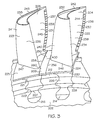
- FIG. 3 is a close-up, isometric view of a portion of the turbine of FIG. 2 indicated by dotted box 3 in an assembled state, according to an embodiment
- FIG. 4 is an isometric view of a spacer, according to an embodiment
- FIG. 5 is another isometric view of the spacer of FIG. 4 , according to an embodiment.
- FIG. 6 is an isometric view of a portion of a turbine, according to another embodiment.
- FIG. 1 is a cross-sectional side view of a portion of a turbine section 100 of an engine, according to an embodiment.
- the turbine section 100 receives high temperature (e.g, temperature typically in the range of 1100-1800° C.) gases from an upstream engine combustor (not shown) to produce energy for the engine and/or components coupled to the engine.
- the turbine section 100 includes a turbine nozzle 104 that has a plurality of static vanes 106 mounted circumferentially around a ring 108 .
- the static vanes 106 direct the gases from the combustor to a turbine 110 .
- the turbine 110 includes a plurality of blades 112 and spacers 114 (only one of each are shown) that are retained in axial position by a retention plate 116 .
- the gases cause the turbine 110 to spin.
- an outer circumferential wall 118 surrounds the static vanes and the plurality of blades 112 and defines a portion of a compressor plenum 120 .
- the compressor plenum 120 receives bleed air from a compressor section (not shown), which may be directed through one or more openings in the outer circumferential wall 118 towards the plurality of blades 112 to cool the blades 112 .
- FIG. 2 is an exploded view of a portion of a turbine 200 , according to an embodiment
- FIG. 3 is a close-up, isometric view of a portion of the turbine 200 indicated by dotted box 3 in an assembled state, according to an embodiment.
- the turbine 200 includes a hub 202 , blades 204 , 205 and spacers 208 , in accordance with an embodiment.
- the hub 202 is disk-shaped and has an outer rim 210 and an outer peripheral surface 212 .
- the hub 202 may have an outer diameter in a range of from about 2 cm to about 30 cm.
- the outer diameter of the hub 202 may be greater or less than the aforementioned range.
- the hub 202 may have a thickness, or axial length, in a range of from about 5 cm to about 20 cm. In other embodiments, the thickness may be greater or less than the aforementioned range.
- the hub 202 has a plurality of circumferentially formed blade attachment slots 214 , 216 formed in its outer rim 210 . Although fifty-six blade attachment slots 214 , 216 are shown, more or fewer slots may be included in other embodiments. Each blade attachment slot 214 , 216 is configured to attach a respective turbine blade 204 , 205 to the hub 202 , as indicated by arrows 218 , 219 in FIG. 2 . To allow the hub 202 to maintain structural integrity during engine operation, the hub 202 may be made of one or more superalloys, such as nickel-based superalloys, or other types of superalloys.
- superalloys such as nickel-based superalloys, or other types of superalloys.
- the blades 204 , 205 each include a shank 220 , 221 , an airfoil 222 , 223 , a platform 224 , 225 , and a blade attachment section 226 , 227 .
- description of each blade part will be provided with reference to blades 204 , 205 . However, it will be appreciated that the description may be applied to other blades that are not shown, but that may be attached to hub 202 .
- each platform 224 , 225 is configured to radially contain turbine airflow.
- Each blade attachment section 226 , 227 provides an area in which a firtree 228 , 229 is machined.
- the firtree 228 , 229 corresponds with a firtree shape formed in a respective blade attachment slot 214 , 216 .
- any one of numerous other shapes suitable for attaching the blade 204 , 205 to the hub 202 may be alternatively machined therein.
- Each airfoil 222 , 223 has two outer walls 230 , 231 , 232 , 233 , each wall 230 , 231 , 232 , 233 having outer surfaces that define an airfoil shape.
- the airfoil shape includes a leading edge 234 , 235 , a trailing edge 236 , 237 , a pressure side 238 , 239 along the first outer wall 230 , 231 , a suction side 240 , 241 along the second outer wall 232 , 233 , a blade tip 242 , 243 , a pressure side discharge trailing edge slot 244 , 245 , and an airfoil platform fillet 246 , 247 .
- the blades 204 , 205 may be single crystal blades comprising a nickel-based superalloy. Suitable nickel-based superalloys include, but are not limited to, Mar-M-247, SC180, and CMSX3. Though not shown, each blade 204 , 205 may have an internal cooling circuit formed therein. The internal cooling circuit may extend from an opening in the platform 224 , 225 through the blade 204 , 205 and may include various passages that eventually communicate with the trailing edge slot 244 , 245 or other openings (not shown) that may be formed in the blade 204 , 205 .
- the spacer 208 is disposed over at least a portion of the outer peripheral surface 212 of the hub 202 .
- the spacer 208 is positioned between two blade attachment slots 214 , 216 and is, thus, disposed between two blades 204 , 205 .
- FIG. 4 is an isometric view of the spacer 208 shown in FIGS. 2 and 3 , according to an embodiment.
- the spacer 208 has a first side 400 that may be adapted to contact gases flowing across the turbine 200 .
- the spacer 208 may comprise materials having high temperature (e.g., higher than about 1100-1300° C.) capabilities.
- the materials may be a low density (e.g., density of about 0.2 lbm per cubic inches or less) material.
- Suitable materials that may be included in the spacer 208 include, but are not limited to, ceramics such as silicon nitride or ceramic matrix composites, or nickel-based superalloys such as SC180, or intermetallics such as nickel aluminide.
- the spacer 208 may include a protective coating (not shown) or a suitable environmental protective layer capable of improving wear-resistance, oxidation-resistance, thermal insulation, or another property desirable for the operation of the spacer 208 .
- the spacer 208 includes a strip 250 , a first retention flange 252 , and a second retention flange 254 .
- the strip 250 is adapted to maintain a predetermined distance between the two blades 204 , 205 and has a first edge 256 , a second edge 258 , and an impingement surface 260 , in an embodiment.
- the first edge 256 abuts the first blade 204
- the second edge 258 abuts the second blade 205 .
- the first and second edges 256 , 258 are parallel to each other. In other embodiments, the edges 256 , 258 may be non-parallel.
- the impingement surface 260 is configured to define a portion of a flowpath for the gases that flow across the turbine 200 .
- the impingement surface 260 is located on the first side 400 of the spacer 208 and extends axially along the strip 250 between the first edge 256 and the second edge 258 .
- the impingement surface 260 is substantially flat and lies substantially flush with surfaces of the platforms 224 , 225 of the blades 204 , 205 .
- the impingement surface 260 has a width measured between the first and second edges 256 , 258 that is substantially uniform along a length of the strip 250 .
- the width may be substantially equal to the predetermined distance between the blades 204 , 205 . In still another embodiment, the width may be slightly less than the predetermined distance between the blades 204 , 205 . In any case, in an example, the width may be in a range of from about 0.02 cm to about 2 cm. In other embodiments, the width may be greater or less than the aforementioned range.
- the impingement surface 260 may have an axial length that is substantially equal to a thickness or axial length of the hub 202 , in an embodiment. In accordance with another embodiment, the axial length of the impingement surface 260 may be less than the thickness of the hub 202 . For example, the axial length may be in a range of from about 0.5 cm to about 10 cm. In other embodiments, the axial length may be greater than or less than the aforementioned range.
- the first retention flange 252 is recessed relative to the impingement surface 260 and extends away from the first edge 256 of the strip 250 .
- the first retention flange 252 may have an approximately semi-ovular shape and may have a smooth, rounded surface.
- the first retention flange 252 may include irregularities formed in its surface and may include a groove or indentation 264 .
- the first retention flange 252 may be rectangular or another suitable shape; however, it will be appreciated that the particular shape of the first retention flange 252 and contour of its surface may depend on a particular shape of the platform 224 , 225 of the blade 204 , 205 and the outer peripheral surface 212 of the hub 202 between which the first retention flange 252 is intended to retain.
- the first retention flange 252 may have a widest width measured from the first edge 256 to a furthest outer edge 262 that is in a range of from about 0.1 cm to about 2 cm and an axial length in a range of from about 0.5 cm to about 10 cm.
- the first retention flange 252 may be recessed a distance from the first edge 256 , where the distance is in a range of from about 1 mm to about 10 mm.
- the particular dimensions of the width, axial length, and recess distance of the first retention flange 252 may be greater or less than the aforementioned ranges and may depend on a particular configuration of a platform 224 , 225 of a blade 204 , 205 .
- the second retention flange 254 is recessed relative to the impingement surface 260 and extends away from the second edge 258 of the strip 250 . According to an embodiment, the second retention flange 254 and the first retention flange 252 are located at substantially identical axial positions along the strip 250 . In one example, the retention flanges 252 , 254 overlap in axial positions.
- the second retention flange 254 may have an approximately semi-ovular shape and may have a smooth, rounded surface. In another embodiment, the second retention flange 254 may include irregularities formed in its surface and may include a groove or indentation 266 . In other embodiments, the second retention flange 254 may be rectangular or another suitable shape. In accordance with still another embodiment, the second retention flange 254 may have a shape that is substantially a mirror image of the first retention flange 252 .
- the particular shape of the second retention flange 254 and contour of its surface may depend on a particular shape of the platform 224 , 225 of the blade 204 , 205 and the outer peripheral surface 212 of the hub 202 between which the second retention flange 254 will be retained.
- the second retention flange 254 may have a widest width measured from the second edge 258 to a furthest outer edge 268 that is in a range of from about 0.1 to about 2 cm and an axial length in a range of from about 0.5 cm to about 10 cm.
- the second retention flange 254 may be recessed a distance from the second edge 258 , where the distance is in a range of from about 1 mm to about 10 mm.
- the second retention flange 254 may have dimensions that are substantially similar to those of the first retention flange 252 .
- the second retention flange 254 may have smaller or larger dimensions than the first retention flange 252 .
- the particular dimensions of the width, axial length, and recess distance of the second retention flange 254 may be greater or less than the aforementioned ranges and may depend on a particular configuration of a platform 224 , 225 of a blade 204 , 205 .
- FIG. 5 is an isometric view of a spacer 508 , according to an embodiment.
- the spacer 508 in FIG. 5 may be substantially identical to spacer 208 depicted in FIGS. 2-4 , except a second side 500 of the spacer 508 is depicted.
- the second side 500 of the spacer 508 is adapted to face radially inwardly toward a hub and may be contoured.
- the spacer 508 includes a strip section 550 and retention flange sections 552 , 554 .
- the strip section 550 may be recessed relative to the retention flanges sections 552 , 554 and may include end walls 530 , 532 that partially define an axial cavity 555 .
- the retention flanges sections 552 , 554 may be disposed on either side of the axial cavity 555 having inner surfaces to define side cavities 557 , 559 .
- a longest axial length of the axial cavity 555 may be in a range of from about 0.5 cm to about 10 cm, in an embodiment, and a total width including a width of the axial cavity 555 and widths of the side cavities 557 , 559 may be in an range of from about 0.2 cm to about 5 cm. In other embodiments, the lengths and widths may be greater or less than the aforementioned ranges.
- the cavities 555 , 557 , 559 may be adapted to circulate received cool air and may have an optimized surface contour for doing so.
- the inner surfaces defining the cavity 555 , 557 , 559 may be relatively smooth.
- the inner surfaces may include grooves, projections or other flow-interrupting features to increase flow circulation within the cavity 555 , 557 , 559 .
- a coating or layer of material (not shown) may be included to improve oxidation, corrosion, or wear-resistance.
- suitable materials may include, but are not limited to aluminide, platinum aluminide, or thermal barrier coatings.
- the spacer 508 may include one or two axial sections 556 , 558 .
- the first axial section 556 may extend axially past first ends 560 , 562 of the first and second retention flanges sections 552 , 554 .
- the spacer 508 may additionally or alternatively include the second axial section 558 extending axially past second ends 564 , 566 of the first and second retention flanges sections 552 , 554 .
- the first and/or second axial sections 556 , 558 extend past the end walls 530 , 532 , respectively, that partially define the axial cavity 555 .
- FIG. 6 is an isometric view of a portion of a turbine 600 , according to another embodiment.
- turbine 600 is substantially identical to turbine 200 , except that turbine 600 includes a blade 604 with an abbreviated platform 624 and a widened spacer 608 .
- the platform 624 has an axially-extending edge 626 having a curved section proximate a pressure side wall 628 of an airfoil 630 extending from the platform 624 .
- the axially-extending edge 626 may continue along a leading edge 632 of the airfoil 630 such that the platform 624 provides little to no flow surface adjacent to the airfoil leading edge 632 .
- the spacer 608 may have a strip 650 having first and second edges 652 , 654 that are non-parallel and that are not straight edges. Instead, the edges (e.g., first edge 652 of the strip 650 ) may have a contour that follows that of the axially-extending edge 626 of the platform 624 .
- blades and spacers may depend on the number of blade attachment slots.
- a number of blades and a number of spacers may be equal to the number of total blade attachment slots.
- the above-described turbine may reduce thermal distress during engine operation, as compared with conventional turbines.
- the blades and the spacers expand outwardly from a hub to which the blades are attached, as a result of centrifugal forces acting on the turbine.
- the outward expansion allows the spacers to seal openings that may be present between the blades and/or hub, which prevents hot gases flowing from the combustor from entering an internal cooling circuit that may be formed in the blade.
- cool air flowing through the internal cooling circuit may remain cool as it flows to various portions of the blade.
- the spacer may act as a friction damper. Specifically, the spacer may create friction when contacting the blades, which dampens vibration that may be experienced by the blades.
Landscapes
- Engineering & Computer Science (AREA)
- Mechanical Engineering (AREA)
- General Engineering & Computer Science (AREA)
- Turbine Rotor Nozzle Sealing (AREA)
Priority Applications (2)
| Application Number | Priority Date | Filing Date | Title |
|---|---|---|---|
| US12/261,305 US8070448B2 (en) | 2008-10-30 | 2008-10-30 | Spacers and turbines |
| EP09173985.4A EP2182171A3 (fr) | 2008-10-30 | 2009-10-23 | Distanceur entre deux aubes de turbine adjacentes |
Applications Claiming Priority (1)
| Application Number | Priority Date | Filing Date | Title |
|---|---|---|---|
| US12/261,305 US8070448B2 (en) | 2008-10-30 | 2008-10-30 | Spacers and turbines |
Publications (2)
| Publication Number | Publication Date |
|---|---|
| US20100111699A1 US20100111699A1 (en) | 2010-05-06 |
| US8070448B2 true US8070448B2 (en) | 2011-12-06 |
Family
ID=41666769
Family Applications (1)
| Application Number | Title | Priority Date | Filing Date |
|---|---|---|---|
| US12/261,305 Active 2030-07-22 US8070448B2 (en) | 2008-10-30 | 2008-10-30 | Spacers and turbines |
Country Status (2)
| Country | Link |
|---|---|
| US (1) | US8070448B2 (fr) |
| EP (1) | EP2182171A3 (fr) |
Cited By (6)
| Publication number | Priority date | Publication date | Assignee | Title |
|---|---|---|---|---|
| US20120057988A1 (en) * | 2009-03-05 | 2012-03-08 | Mtu Aero Engines Gmbh | Rotor for a turbomachine |
| US20120156045A1 (en) * | 2010-12-17 | 2012-06-21 | General Electric Company | Methods, systems and apparatus relating to root and platform configurations for turbine rotor blades |
| EP3053694A2 (fr) | 2014-11-24 | 2016-08-10 | Honeywell International Inc. | Rotor de turbine assemblé hybride et procédés de fabrication de ce dernier |
| US9951632B2 (en) | 2015-07-23 | 2018-04-24 | Honeywell International Inc. | Hybrid bonded turbine rotors and methods for manufacturing the same |
| US10975714B2 (en) * | 2018-11-22 | 2021-04-13 | Pratt & Whitney Canada Corp. | Rotor assembly with blade sealing tab |
| US11486261B2 (en) * | 2020-03-31 | 2022-11-01 | General Electric Company | Turbine circumferential dovetail leakage reduction |
Families Citing this family (4)
| Publication number | Priority date | Publication date | Assignee | Title |
|---|---|---|---|---|
| US8172534B2 (en) * | 2009-01-21 | 2012-05-08 | General Electric Company | Turbine blade or vane with improved cooling |
| FR2963382B1 (fr) * | 2010-08-02 | 2016-01-29 | Snecma | Roue de turbine a aubes en composite a matrice ceramique |
| WO2014190008A1 (fr) * | 2013-05-23 | 2014-11-27 | General Electric Company | Pale de compresseur composite et procédé d'assemblage |
| US20200318486A1 (en) | 2019-04-04 | 2020-10-08 | General Electric Company | Monolithic Composite Blade and Platform |
Citations (12)
| Publication number | Priority date | Publication date | Assignee | Title |
|---|---|---|---|---|
| US3635587A (en) * | 1970-06-02 | 1972-01-18 | Gen Motors Corp | Blade cooling liner |
| US3653781A (en) * | 1970-12-18 | 1972-04-04 | Gen Electric | Turbomachinery blade retainer |
| US3832092A (en) * | 1973-10-19 | 1974-08-27 | Gen Electric | Device for locking turbomachinery blades |
| US4265595A (en) * | 1979-01-02 | 1981-05-05 | General Electric Company | Turbomachinery blade retaining assembly |
| US4872812A (en) | 1987-08-05 | 1989-10-10 | General Electric Company | Turbine blade plateform sealing and vibration damping apparatus |
| US4921405A (en) * | 1988-11-10 | 1990-05-01 | Allied-Signal Inc. | Dual structure turbine blade |
| US6435813B1 (en) * | 2000-05-10 | 2002-08-20 | General Electric Company | Impigement cooled airfoil |
| US20050042077A1 (en) * | 2002-10-23 | 2005-02-24 | Eugene Gekht | Sheet metal turbine or compressor static shroud |
| US20050135921A1 (en) * | 2003-12-17 | 2005-06-23 | Busch Duane A. | Inboard cooled nozzle doublet |
| US7137783B2 (en) | 2003-06-30 | 2006-11-21 | Snecma Moteurs | Cooled gas turbine blades |
| US7374400B2 (en) | 2004-03-06 | 2008-05-20 | Rolls-Royce Plc | Turbine blade arrangement |
| US7713029B1 (en) * | 2007-03-28 | 2010-05-11 | Florida Turbine Technologies, Inc. | Turbine blade with spar and shell construction |
Family Cites Families (5)
| Publication number | Priority date | Publication date | Assignee | Title |
|---|---|---|---|---|
| GB9828484D0 (en) * | 1998-12-24 | 1999-02-17 | Rolls Royce Plc | Improvements in or relating to bladed structures for fluid flow propulsion engines |
| US6634863B1 (en) * | 2000-11-27 | 2003-10-21 | General Electric Company | Circular arc multi-bore fan disk assembly |
| FR2840352B1 (fr) * | 2002-05-30 | 2005-12-16 | Snecma Moteurs | Maitrise de la zone de fuite sous plate-forme d'aube |
| US7121800B2 (en) * | 2004-09-13 | 2006-10-17 | United Technologies Corporation | Turbine blade nested seal damper assembly |
| FR2914008B1 (fr) * | 2007-03-21 | 2009-10-09 | Snecma Sa | Ensemble rotatif d'une soufflante de turbomachine |
-
2008
- 2008-10-30 US US12/261,305 patent/US8070448B2/en active Active
-
2009
- 2009-10-23 EP EP09173985.4A patent/EP2182171A3/fr not_active Withdrawn
Patent Citations (12)
| Publication number | Priority date | Publication date | Assignee | Title |
|---|---|---|---|---|
| US3635587A (en) * | 1970-06-02 | 1972-01-18 | Gen Motors Corp | Blade cooling liner |
| US3653781A (en) * | 1970-12-18 | 1972-04-04 | Gen Electric | Turbomachinery blade retainer |
| US3832092A (en) * | 1973-10-19 | 1974-08-27 | Gen Electric | Device for locking turbomachinery blades |
| US4265595A (en) * | 1979-01-02 | 1981-05-05 | General Electric Company | Turbomachinery blade retaining assembly |
| US4872812A (en) | 1987-08-05 | 1989-10-10 | General Electric Company | Turbine blade plateform sealing and vibration damping apparatus |
| US4921405A (en) * | 1988-11-10 | 1990-05-01 | Allied-Signal Inc. | Dual structure turbine blade |
| US6435813B1 (en) * | 2000-05-10 | 2002-08-20 | General Electric Company | Impigement cooled airfoil |
| US20050042077A1 (en) * | 2002-10-23 | 2005-02-24 | Eugene Gekht | Sheet metal turbine or compressor static shroud |
| US7137783B2 (en) | 2003-06-30 | 2006-11-21 | Snecma Moteurs | Cooled gas turbine blades |
| US20050135921A1 (en) * | 2003-12-17 | 2005-06-23 | Busch Duane A. | Inboard cooled nozzle doublet |
| US7374400B2 (en) | 2004-03-06 | 2008-05-20 | Rolls-Royce Plc | Turbine blade arrangement |
| US7713029B1 (en) * | 2007-03-28 | 2010-05-11 | Florida Turbine Technologies, Inc. | Turbine blade with spar and shell construction |
Cited By (10)
| Publication number | Priority date | Publication date | Assignee | Title |
|---|---|---|---|---|
| US20120057988A1 (en) * | 2009-03-05 | 2012-03-08 | Mtu Aero Engines Gmbh | Rotor for a turbomachine |
| US20120156045A1 (en) * | 2010-12-17 | 2012-06-21 | General Electric Company | Methods, systems and apparatus relating to root and platform configurations for turbine rotor blades |
| EP3053694A2 (fr) | 2014-11-24 | 2016-08-10 | Honeywell International Inc. | Rotor de turbine assemblé hybride et procédés de fabrication de ce dernier |
| US9951632B2 (en) | 2015-07-23 | 2018-04-24 | Honeywell International Inc. | Hybrid bonded turbine rotors and methods for manufacturing the same |
| US10975714B2 (en) * | 2018-11-22 | 2021-04-13 | Pratt & Whitney Canada Corp. | Rotor assembly with blade sealing tab |
| US12070811B2 (en) | 2018-11-22 | 2024-08-27 | Pratt & Whitney Canada Corp. | Method of manufacturing a rotor disc for a turbine engine |
| US12467375B2 (en) | 2018-11-22 | 2025-11-11 | Pratt & Whitney Canada Corp. | Blade for a rotor assembly of a turbine engine |
| US11486261B2 (en) * | 2020-03-31 | 2022-11-01 | General Electric Company | Turbine circumferential dovetail leakage reduction |
| US20230037224A1 (en) * | 2020-03-31 | 2023-02-02 | General Electric Company | Turbine circumferential dovetail leakage reduction |
| US11920498B2 (en) * | 2020-03-31 | 2024-03-05 | General Electric Company | Turbine circumferential dovetail leakage reduction |
Also Published As
| Publication number | Publication date |
|---|---|
| EP2182171A2 (fr) | 2010-05-05 |
| EP2182171A3 (fr) | 2013-06-26 |
| US20100111699A1 (en) | 2010-05-06 |
Similar Documents
| Publication | Publication Date | Title |
|---|---|---|
| US8070448B2 (en) | Spacers and turbines | |
| US10077680B2 (en) | Blade outer air seal assembly and support | |
| US8240981B2 (en) | Turbine airfoil with platform cooling | |
| US10323534B2 (en) | Blade outer air seal with cooling features | |
| EP2434097B1 (fr) | Aube rotorique de turbine | |
| US5857837A (en) | Coolable air foil for a gas turbine engine | |
| US8172533B2 (en) | Turbine blade internal cooling configuration | |
| US8408872B2 (en) | Fastback turbulator structure and turbine nozzle incorporating same | |
| EP1106782B1 (fr) | Aube refroidie pour turbine à gaz et sa méthode de fabrication | |
| EP3006670B1 (fr) | Aubes de turbine présentant des structures de turbulateur à nervure relevée | |
| CA2613790C (fr) | Profiles couronnes soutenant des elements arques | |
| US20150118063A1 (en) | Turbine airfoil tip shelf and squealer pocket cooling | |
| US20150292334A1 (en) | Turbine airfoil tip shelf and squealer pocket cooling | |
| CN102678187B (zh) | 涡轮发动机系统及用于燃气涡轮发动机的涡轮机轮叶 | |
| WO2013158194A1 (fr) | Plateau de pointe d'ailette de turbine et refroidissement à poche d'indicateur de fuite audible | |
| US10472980B2 (en) | Gas turbine seals | |
| US12221898B2 (en) | Turbine incorporating splitters | |
| EP2639405B1 (fr) | Refroidissement d'extrémité d'aube de turbine | |
| US20150104327A1 (en) | Turbine rotor blades with tip portion parapet wall cavities | |
| CA2803171C (fr) | Fentes eliminant des contraintes d'une bague d'aubes de turbine | |
| US20190264569A1 (en) | Turbine rotor blade with exiting hole to deliver fluid to boundary layer film | |
| GB2473949A (en) | Heat transfer apparatus with turbulators |
Legal Events
| Date | Code | Title | Description |
|---|---|---|---|
| AS | Assignment |
Owner name: HONEYWELL INTERNATIONAL INC.,NEW JERSEY Free format text: ASSIGNMENT OF ASSIGNORS INTEREST;ASSIGNORS:MORRIS, MARK C.;ORTIZ, MILTON;WALDMAN, DAVID;AND OTHERS;SIGNING DATES FROM 20081029 TO 20081030;REEL/FRAME:021761/0916 Owner name: HONEYWELL INTERNATIONAL INC., NEW JERSEY Free format text: ASSIGNMENT OF ASSIGNORS INTEREST;ASSIGNORS:MORRIS, MARK C.;ORTIZ, MILTON;WALDMAN, DAVID;AND OTHERS;SIGNING DATES FROM 20081029 TO 20081030;REEL/FRAME:021761/0916 |
|
| STCF | Information on status: patent grant |
Free format text: PATENTED CASE |
|
| FPAY | Fee payment |
Year of fee payment: 4 |
|
| MAFP | Maintenance fee payment |
Free format text: PAYMENT OF MAINTENANCE FEE, 8TH YEAR, LARGE ENTITY (ORIGINAL EVENT CODE: M1552); ENTITY STATUS OF PATENT OWNER: LARGE ENTITY Year of fee payment: 8 |
|
| MAFP | Maintenance fee payment |
Free format text: PAYMENT OF MAINTENANCE FEE, 12TH YEAR, LARGE ENTITY (ORIGINAL EVENT CODE: M1553); ENTITY STATUS OF PATENT OWNER: LARGE ENTITY Year of fee payment: 12 |