US8070491B2 - Holding element for a dental implant - Google Patents
Holding element for a dental implant Download PDFInfo
- Publication number
- US8070491B2 US8070491B2 US11/497,712 US49771206A US8070491B2 US 8070491 B2 US8070491 B2 US 8070491B2 US 49771206 A US49771206 A US 49771206A US 8070491 B2 US8070491 B2 US 8070491B2
- Authority
- US
- United States
- Prior art keywords
- holding device
- section
- dental implant
- engagement
- force transmission
- Prior art date
- Legal status (The legal status is an assumption and is not a legal conclusion. Google has not performed a legal analysis and makes no representation as to the accuracy of the status listed.)
- Expired - Fee Related, expires
Links
- 239000004053 dental implant Substances 0.000 title claims abstract description 68
- 230000005540 biological transmission Effects 0.000 claims abstract description 36
- 230000014759 maintenance of location Effects 0.000 claims abstract description 15
- 239000003708 ampul Substances 0.000 claims abstract description 9
- 239000004696 Poly ether ether ketone Substances 0.000 claims description 9
- 229920002530 polyetherether ketone Polymers 0.000 claims description 9
- JUPQTSLXMOCDHR-UHFFFAOYSA-N benzene-1,4-diol;bis(4-fluorophenyl)methanone Chemical compound OC1=CC=C(O)C=C1.C1=CC(F)=CC=C1C(=O)C1=CC=C(F)C=C1 JUPQTSLXMOCDHR-UHFFFAOYSA-N 0.000 claims 1
- 230000000717 retained effect Effects 0.000 claims 1
- 239000012530 fluid Substances 0.000 description 4
- RTAQQCXQSZGOHL-UHFFFAOYSA-N Titanium Chemical compound [Ti] RTAQQCXQSZGOHL-UHFFFAOYSA-N 0.000 description 3
- 210000000988 bone and bone Anatomy 0.000 description 3
- 239000007943 implant Substances 0.000 description 3
- 238000004519 manufacturing process Methods 0.000 description 3
- 230000008878 coupling Effects 0.000 description 2
- 238000010168 coupling process Methods 0.000 description 2
- 238000005859 coupling reaction Methods 0.000 description 2
- 238000002513 implantation Methods 0.000 description 2
- 238000004806 packaging method and process Methods 0.000 description 2
- OKTJSMMVPCPJKN-UHFFFAOYSA-N Carbon Chemical compound [C] OKTJSMMVPCPJKN-UHFFFAOYSA-N 0.000 description 1
- 229910052799 carbon Inorganic materials 0.000 description 1
- 239000000463 material Substances 0.000 description 1
- 230000004048 modification Effects 0.000 description 1
- 238000012986 modification Methods 0.000 description 1
- 230000002093 peripheral effect Effects 0.000 description 1
- 239000004033 plastic Substances 0.000 description 1
- 238000000926 separation method Methods 0.000 description 1
Images


Classifications
-
- A—HUMAN NECESSITIES
- A61—MEDICAL OR VETERINARY SCIENCE; HYGIENE
- A61C—DENTISTRY; APPARATUS OR METHODS FOR ORAL OR DENTAL HYGIENE
- A61C8/00—Means to be fixed to the jaw-bone for consolidating natural teeth or for fixing dental prostheses thereon; Dental implants; Implanting tools
- A61C8/0087—Means for sterile storage or manipulation of dental implants
-
- A—HUMAN NECESSITIES
- A61—MEDICAL OR VETERINARY SCIENCE; HYGIENE
- A61C—DENTISTRY; APPARATUS OR METHODS FOR ORAL OR DENTAL HYGIENE
- A61C8/00—Means to be fixed to the jaw-bone for consolidating natural teeth or for fixing dental prostheses thereon; Dental implants; Implanting tools
- A61C8/0089—Implanting tools or instruments
Definitions
- the present invention relates in general to an improved holding element for a dental implant and in particular to an improved coupling of the holding element to the dental implant.
- dental implants may be stored prior to their use in a sealed ampule which is preferably filled with a storage fluid.
- the dental implant is temporarily coupled to a holding element which holding element is used in the course of storage to retain the dental implant firmly in position within the ampule. Later, when the dental implant is removed from the ampule for implantation into a respective bone, the holding element is gripped by the user to be placed into the implant site.
- the holding element is furthermore adapted for temporary positive attachment to manipulating tools that facilitate the removal of the dental implant from the ampule and the placement thereof into the bone at the implant site.
- the holding element may be removed from the dental implant. Nevertheless, as the holding element is screwed to the dental implant, the overall handling is tedious.
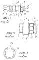
- the known holding element which is generally designated by reference numeral 1 includes an engagement section 2 adapted for positive engagement with a manipulating tool not shown.
- the engagement section 2 is embodied as a polygonally shaped end, for instance as an octagonally shaped end. Adjacent to the engagement section 2 there is provided a radial groove 3 for accommodating an O-ring 3 A shown in FIG. 2 that has a securing function to the manipulating tool not shown.
- the holding element 1 has a retention section 4 with two adjoining annular shoulders 5 and 7 and an intermediate cylindrical section 6 of a reduced diameter adapted for retention in an inner ampule indicated at 20 .
- the retention section 4 is joined to the engagement section 2 by a breaking point member 30 .
- the known holding element 1 further includes, adjacent to the retention section 4 , a clamping section 8 with a first radial groove 9 , a force transmission element 10 with an octagonal shape for the positive engagement with a dental implant 14 , a second radial groove 11 and a tapered member 12 .
- the second radial groove 11 is provided with a clamping or lock ring 13 made of PEEK (poly ether ether ketone) including a peripheral clearance 13 A for facilitating the mounting thereof.
- PEEK poly ether ether ketone
- the dental implant 14 is provided with a cavity 15 having an inner surface 17 that matches the surface of the force transmission element 10 , such as to provide for a positive engagement between the dental implant 14 and the holding element 1 , whereby the dental implant 14 is rotationally secured to the holding element 1 .
- the cavity 15 of the dental implant 14 further includes an undercut 18 sized for clampingly receiving the lock ring 13 and a conical terminal section 19 closely enclosing the first radial grove 9 of the clamping section 8 of the holding element 1 .
- the prior art lock ring tends to release carbon that may in turn damage the surface of a dental implant, particularly an SLA treated dental implant surface.
- the aim of the present invention is to provide for an improved holding element for a dental implant wherein the clamping force can be maintained over a larger time span during which the holding element and the dental implant are stored in an packaging.
- the above aim applies to packaging with or without storage fluids.
- an object of the present invention is to provide a holding element for a dental implant wherein the clamping force can be precisely adjusted.
- Another object of the present invention is to provide for a holding element that minimizes the likelihood of damaging the dental implant and that does not require excessively strict manufacturing tolerances.
- FIG. 1 is side view of a prior art holding element for a dental implant
- FIG. 1A is an enlarged view of a clamping section and of a retention section, in part, of the prior art holding element for a dental implant of FIG. 1 ;
- FIG. 2 is a sectional view of the holding element of FIG. 1 with a coupled dental implant and placed in an inner ampule for storage and transport of the dental implant;
- FIG. 2A is an enlarged sectional view of the clamping section of the holding element of FIGS. 1 and 2 when coupled to the dental implant;
- FIG. 3 shows a top view of a PEEK clamping or lock ring of the prior art holding element of FIG. 1 ;
- FIG. 4 is a perspective view of a holding element for a dental implant according to a first embodiment of the present invention
- FIG. 4A is a cross-sectional view a holding element for a dental implant according to the first embodiment of the present invention.
- FIG. 5 is a perspective view of a holding element for a dental implant according to a second embodiment of the present invention.
- FIG. 5A is an enlarged view of the section of FIG. 5 including a clamping member
- FIG. 6 is a perspective view of a holding element for a dental implant according to a third embodiment of the present invention.
- FIG. 7 is a perspective view of a holding element for a dental implant according to a fourth embodiment of the present invention.
- FIG. 7A is sectional view showing a variation of the fourth embodiment of FIG. 7 with the holding element shown engaged in the undercut of the dental implant;
- FIG. 8 is a perspective view of a holding element for a dental implant according to a fifth embodiment of the present invention.
- FIG. 8A is sectional view of FIG. 8 ;
- FIG. 9 is a perspective view of a holding element for a dental implant according to a sixth embodiment of the present invention.
- FIGS. 4 and 4A there is described a holding element 1 for a dental implant according to a first embodiment of the present invention. It should be noted that elements thereof similar to those of FIGS. 1 through 3 are designated by the same reference numerals and that the description thereof will be omitted.
- the holding element 1 includes, in an similar manner to the prior art of FIGS. 1 through 3 , the engagement section 2 for the positive engagement with a manipulating tool, the radial groove 3 for accommodating the O-ring 3 A, preferably made of PEEK, the breaking point member 30 , the retention section with the two adjoining annular shoulders 5 and 7 and the intermediate cylindrical section 6 of a reduced diameter, and a novel clamping section 8 to be described hereinbelow.
- the engagement section 2 of the present invention is preferably of polygonal and more preferably of octagonal shape.
- the novel clamping section 8 includes a first member 100 adapted for cooperation with the terminal section 19 of the dental implant 14 and connecting to the adjoining annular shoulder 7 , a force transmission element 110 connecting to the first member 100 , and a second member 112 connecting to the force transmission element 110 .
- the first and/or second members 100 , 112 are slightly tapered.
- the force transmission element 110 is preferably polygonally and more preferably octagonally shaped. Nevertheless, the force transmission element 110 can also have a substantially cylindrical or conical shape.
- the force transmission element 110 and the second member 112 axially surround a novel clamping member 113 devised and arranged in accordance with the invention.
- the clamping member 113 is formed with a substantially cylindrical body 113 A and one or more arms 113 B extending radially through respective openings 114 provided in the second member 112 and in the force transmission element 110 .
- the openings 114 may be formed only in the second member 112 , such that the radial arm or arms 113 B would extend adjacent to the force transmission element 110 .
- the clamping member 113 has a certain elasticity, such that the arms 113 B can be compressed radially with the extremities or protrusions 113 C thereof extending in the non-compressed position beyond the perimeter defined by the force transmission element 110 . If the opening 114 is only formed in the second member 112 the extremities or protrusions of the arms 113 B would accordingly only extend in the non-compressed position beyond the perimeter defined by the second member 112 , however, to an extent sufficient to provide the clamping cooperation with an undercut 18 (not shown) of the dental implant 14 .
- the implant holder 1 of the first embodiment except for the O-ring 3 A and the clamping member 113 , is manufactured of titan with the latter being made of PEEK, although an appropriate plastic material can also be used.
- the force transmission element 110 if shaped octagonally, allows a plurality of rotational positions, with four radial arms 113 B extending through non-adjacent surfaces thereof.
- the cavity 15 of the dental implant 14 is provided with the undercut 18 (not shown in connection with FIGS. 4 and 4A ) to accommodate the radial arms 113 B in the non-compressed position thereof.
- the clamping member 113 can be molded into a cavity of the holding element 1 , as shown in FIG. 4A , and the extension of the cylindrical body 113 A into the cavity 15 of the dental implant 1 and its size are such that a good connection stability is provided.
- the second member 112 may also be sized to closely fit the cavity 15 of the dental implant to improve the stability of the connection.
- FIGS. 5 and 5A there is described a holding element 1 for a dental implant according to a second embodiment of the present invention. It should be noted that elements thereof similar to those of FIGS. 1 through 4B are designated by the same reference numerals and that the description thereof will be omitted.
- the novel clamping section 8 includes a first member 200 adapted for cooperation with the terminal section 19 of the dental implant 14 and connecting to the adjoining annular shoulder 7 and a force transmission element 210 connecting to the first member 200 .
- the first member 200 is slightly tapered and the force transmission element 210 is preferably polygonal and more preferably octagonal. Nevertheless, the force transmission element 210 can also have a substantially cylindrical or conical shape.
- a clamping member 213 according to the second embodiment of the invention includes an arm 213 B which can be preferably milled from a lateral wall of the force transmission element 210 .
- the extremity or protrusion 213 C of the arm 213 B extends, in the non-compressed position thereof, beyond the perimeter defined by force transmission element 210 , such as to lockingly engage an undercut 18 (not shown in connection with FIGS. 5 and 5A ) provided in the cavity 15 of the dental implant 14 .
- the clamping section of the embodiment of FIGS. 5 and 5A further includes a substantially cylindrical body 213 A extending from within the force transmission element 210 and sized to fit the cavity 15 of the dental implant 1 such that a good connection stability is provided.
- a clearance shown at 215 is present between the inner surface of the force transmission element 210 and the cylindrical body 213 A.
- the holding element of the second embodiment is preferably made of titan.
- FIG. 6 With reference to FIG. 6 there is described a holding element 1 for a dental implant according to a third embodiment of the present invention. It should be noted that elements thereof similar to those of FIGS. 5 and 5A are designated by the same reference numerals and that the description thereof will be omitted.
- the first member is devised as a circular groove 200 ′ and there is provided a second member 216 protruding from the force transmission element 210 such as to further improve the stability of the connection between the holding element 1 and the dental implant 14 .
- the clamping member 313 includes a body 313 A shaped substantially as a parallelepiped with preferably two arms 313 B extending from a middle section of the parallelepiped body 313 A.
- the arms 313 B are provided with respective protrusions 313 C.
- the clamping member 313 of the latter embodiment may be manufactured of PEEK or titan.
- the arms 313 B extend from a lower section of the parallelepiped body 313 A. Furthermore, in FIG. 7A the holding element 1 is shown engaged in the undercut 18 of the dental implant 14 .
- FIGS. 8 and 8B there is described a holding element 1 for a dental implant according to a fifth embodiment of the present invention.
- the arm 213 B′′ of the clamping element 213 is in the shape of a pinhead inserted into a recess provided in the force transmission element 210 and in the second member 216 , with the pinhead shaped arm 213 B′′ having a suitable elasticity.
- the clearance 215 between the inner surface of the force transmission element 210 and the cylindrical body 213 A may be omitted in this embodiment, as shown in FIGS. 8 and 8A .
- FIG. 9 there is described a holding element 1 for a dental implant according to a sixth embodiment of the present invention.
- the clamping element 413 is provided by means of a flexible arm 413 B formed as a clip extending parallel to the axis of the holding element 1 .
- a protrusion 413 C of the arm 413 B extends yet again in the non-compressed position beyond the perimeter defined by the force transmission element 210 .
- the clip can be milled or otherwise manufactured from a lateral wall of the force transmission element 210 .
- an additional flexible arm 413 D in the shape of a clip may be provided on the annular shoulder 7 so as to further enhance the clamping force available for connecting the dental holder to the dental implant.
- the clearance 215 between the inner surface of the force transmission element 210 and the cylindrical body 413 A may also be omitted.
- the holding element of the present invention is intended to be stored in a package with or without a storage fluid.
- the package may be possibly embodied as an ampule of the type described in the prior art publications WO-A1-2005/037126 or U.S. Pat. No. 6,261,097B1.
Landscapes
- Health & Medical Sciences (AREA)
- Oral & Maxillofacial Surgery (AREA)
- Orthopedic Medicine & Surgery (AREA)
- Dentistry (AREA)
- Epidemiology (AREA)
- Life Sciences & Earth Sciences (AREA)
- Animal Behavior & Ethology (AREA)
- General Health & Medical Sciences (AREA)
- Public Health (AREA)
- Veterinary Medicine (AREA)
- Dental Prosthetics (AREA)
- Dental Preparations (AREA)
Priority Applications (1)
| Application Number | Priority Date | Filing Date | Title |
|---|---|---|---|
| US13/281,811 US8303307B2 (en) | 2005-08-03 | 2011-10-26 | Holding element for a dental implant |
Applications Claiming Priority (3)
| Application Number | Priority Date | Filing Date | Title |
|---|---|---|---|
| EP05107165.2 | 2005-03-08 | ||
| EP05107165A EP1749501B1 (de) | 2005-08-03 | 2005-08-03 | Halteelement für ein Zahnimplantat |
| EP05107165 | 2005-08-03 |
Related Child Applications (1)
| Application Number | Title | Priority Date | Filing Date |
|---|---|---|---|
| US13/281,811 Continuation US8303307B2 (en) | 2005-08-03 | 2011-10-26 | Holding element for a dental implant |
Publications (2)
| Publication Number | Publication Date |
|---|---|
| US20060269890A1 US20060269890A1 (en) | 2006-11-30 |
| US8070491B2 true US8070491B2 (en) | 2011-12-06 |
Family
ID=34940335
Family Applications (2)
| Application Number | Title | Priority Date | Filing Date |
|---|---|---|---|
| US11/497,712 Expired - Fee Related US8070491B2 (en) | 2005-08-03 | 2006-08-02 | Holding element for a dental implant |
| US13/281,811 Expired - Fee Related US8303307B2 (en) | 2005-08-03 | 2011-10-26 | Holding element for a dental implant |
Family Applications After (1)
| Application Number | Title | Priority Date | Filing Date |
|---|---|---|---|
| US13/281,811 Expired - Fee Related US8303307B2 (en) | 2005-08-03 | 2011-10-26 | Holding element for a dental implant |
Country Status (5)
| Country | Link |
|---|---|
| US (2) | US8070491B2 (de) |
| EP (1) | EP1749501B1 (de) |
| AT (1) | ATE483419T1 (de) |
| DE (1) | DE602005023979D1 (de) |
| ES (1) | ES2351277T3 (de) |
Cited By (11)
| Publication number | Priority date | Publication date | Assignee | Title |
|---|---|---|---|---|
| US20130171584A1 (en) * | 2011-12-30 | 2013-07-04 | Nobel Biocare Services Ag | Abutment position locator |
| US20130230825A1 (en) * | 2012-03-01 | 2013-09-05 | Straumann Holding Ag | Holding device for dental implant |
| US20130309630A1 (en) * | 2011-01-25 | 2013-11-21 | Dentalpoint Ag | Denture system |
| US20150250565A1 (en) * | 2012-10-02 | 2015-09-10 | Straumann Holding Ag | Insertion tool |
| US9700397B2 (en) | 2015-11-30 | 2017-07-11 | Metal Industries Research & Development Centre | Implant carrier, mixing pot, and implant carrier assembly |
| USD799933S1 (en) * | 2016-05-13 | 2017-10-17 | Olson Kundig, Inc. | No-peek latch |
| US9925024B2 (en) | 2011-06-28 | 2018-03-27 | Biomet 3I, Llc | Dental implant and abutment tools |
| TWI621425B (zh) * | 2013-11-28 | 2018-04-21 | 財團法人金屬工業研究發展中心 | 骨植入物 |
| US10285796B2 (en) * | 2015-07-01 | 2019-05-14 | Nantoh. Co., Ltd | Prosthesis packaging case, prosthesis, and prosthesis with packaging case |
| US10631994B2 (en) | 2012-10-12 | 2020-04-28 | Smith & Nephew, Inc. | Fusion Implant |
| US20210212805A1 (en) * | 2016-06-02 | 2021-07-15 | Camlog Biotechnologies Gmbh | Retainer, combination of a packaging and a retainer, adapter and a retainer with a support structure for a surgical device |
Families Citing this family (15)
| Publication number | Priority date | Publication date | Assignee | Title |
|---|---|---|---|---|
| DE112007001956B4 (de) * | 2006-09-13 | 2010-10-21 | Danfoss A/S | Brennstoff-Einspritzdüsenanordnung |
| DE102007026504A1 (de) * | 2007-06-05 | 2008-12-11 | Straumann Holding Ag | Aufnahmeelement für ein Implantat |
| WO2009147166A1 (de) | 2008-06-06 | 2009-12-10 | Thommen Medical Ag | Verpackung für dentalimplantat |
| US8075313B2 (en) * | 2009-01-19 | 2011-12-13 | Aeton Medical Llc | Transfer copings and related methods for taking implant impressions |
| EP2279708B1 (de) | 2009-07-27 | 2013-05-15 | Straumann Holding AG | Behälter für ein medizinisches Instrument oder Implantat, insbesondere ein dentalmedizinisches Instrument oder ein Dentalimplantat |
| FR2948279B1 (fr) * | 2009-07-27 | 2012-08-24 | Luponax Plastic | Dispositif de conditionnement pour implant dentaire |
| JP2014515952A (ja) | 2011-05-13 | 2014-07-07 | シュトラウマン・ホールディング・アクチェンゲゼルシャフト | 挿入具 |
| US10441386B2 (en) | 2011-06-02 | 2019-10-15 | MIS Implants Technologies Ltd. | Dental implant |
| EP4166109B1 (de) * | 2013-01-10 | 2024-07-24 | Straumann Holding AG | Ringförmiges elastisches halteelement |
| JP2017506122A (ja) * | 2014-02-20 | 2017-03-02 | エムアイエス インプランツ テクノロジーズ リミテッド | 歯科インプラント |
| CH710129A1 (de) * | 2014-09-19 | 2016-03-31 | Cendres & Métaux Sa | Instrument, insbesondere Schraubendreher, zur Handhabung eines Dentalteils, insbesondere eines Patrizenteils. |
| EP2997931B1 (de) | 2014-09-19 | 2019-12-11 | Cendres + Métaux SA | Instrument zur handhabung eines dentalteils |
| DE202017107751U1 (de) * | 2017-12-20 | 2018-12-21 | Straumann Holding Ag | Behälter für ein Zahnimplantat |
| KR102423053B1 (ko) * | 2020-06-05 | 2022-08-25 | 주식회사 워랜텍 | 임플란트용 어버트먼트 제거 장치 |
| EP4525776A1 (de) | 2022-05-19 | 2025-03-26 | Universität für Bodenkultur Wien | Verbesserter zahnimplantatbehälter und implantat |
Citations (39)
| Publication number | Priority date | Publication date | Assignee | Title |
|---|---|---|---|---|
| US4856648A (en) * | 1987-12-31 | 1989-08-15 | Steri-Oss, Inc. | Packaging & installing implants |
| US5328371A (en) * | 1992-10-23 | 1994-07-12 | Friatec Aktiengesellschaft | Dental implant |
| US5368160A (en) * | 1993-12-21 | 1994-11-29 | Calcitek, Inc. | Sterile packaging for dental implant system |
| US5538428A (en) * | 1994-04-05 | 1996-07-23 | Attachments International | Packing delivery system for dental implant and method |
| US5558230A (en) * | 1995-06-07 | 1996-09-24 | Ultradent Products | Dental implant container with cap for holding a dental implant and healing screw |
| US5582299A (en) * | 1994-03-01 | 1996-12-10 | Implant Innovations, Inc. | Dental implant packaging |
| US5622500A (en) * | 1994-02-24 | 1997-04-22 | Core-Vent Corporation | Insertion tool/healing collar/abutment |
| US5782918A (en) * | 1996-12-12 | 1998-07-21 | Folsom Metal Products | Implant abutment system |
| WO1998053755A1 (de) | 1997-05-26 | 1998-12-03 | Friadent Gmbh | Verpackung mit einem behälter und einem in diesem angeordneten dentalimplantat |
| US5996779A (en) * | 1998-06-19 | 1999-12-07 | Lifecore Biomedical, Inc. | Dental implant package |
| WO2000002496A1 (en) | 1998-07-13 | 2000-01-20 | Nobel Biocare Ab | Combination implant carrier and vial cap |
| US6086371A (en) * | 1998-02-05 | 2000-07-11 | Sulzer Orthopedics Inc. | Dental implant delivery system having driver mount with removable flange |
| US6099311A (en) * | 1999-07-28 | 2000-08-08 | Sulzer Calcitek Inc. | Abutment delivery system |
| US6261097B1 (en) * | 1997-06-02 | 2001-07-17 | Institut Straumann Ag | Retaining element for an implant and ampoule for preserving said implant |
| WO2001050978A1 (en) | 2000-01-14 | 2001-07-19 | Nobel Biocare Ab | Universal implant delivery system |
| US6280192B1 (en) * | 1999-03-24 | 2001-08-28 | Degussa Ag | Device for handling dental implants |
| US20010019816A1 (en) | 1999-08-12 | 2001-09-06 | Ajay Kumar | Universal implant delivery system |
| US6312260B1 (en) * | 1998-08-12 | 2001-11-06 | Nobel Biocare Ab | One-step threaded implant |
| US6315562B1 (en) * | 1998-07-13 | 2001-11-13 | Nobel Biocare Usa, Inc. | Implant carrier with gripping fingers |
| US6332777B1 (en) * | 1997-05-24 | 2001-12-25 | Franz Sutter | Device for forming a dental prosthesis |
| US6358050B1 (en) * | 1997-08-19 | 2002-03-19 | Astra Aktiebolag | Dental implant systems |
| US6394809B2 (en) * | 1997-10-03 | 2002-05-28 | Implant Innovations, Inc. | Single-stage implant system |
| US6394806B1 (en) * | 1999-09-14 | 2002-05-28 | Nobel Biocare Usa, Inc | Snap-in healing cap |
| US6416324B1 (en) | 1999-12-10 | 2002-07-09 | Sulzer Dental Inc. | One step dental implant delivery system |
| US6428318B2 (en) * | 2000-04-14 | 2002-08-06 | Alberto Arruga Artal | Dental implant and operative method of implantation |
| US6517543B1 (en) * | 1999-08-17 | 2003-02-11 | Pioneer Laboratories, Inc. | Bone connector system with anti-rotational feature |
| US20030221977A1 (en) * | 2002-06-04 | 2003-12-04 | Ajay Kumar | Dental implant vial with activation mechanism |
| US20030224325A1 (en) * | 2002-06-04 | 2003-12-04 | Ajay Kumar | Dental tool with rententive feature |
| US6663389B1 (en) * | 1999-03-16 | 2003-12-16 | Antonio Gallicchio | Implant for artificial teeth |
| US20040101808A1 (en) * | 2002-11-13 | 2004-05-27 | Porter Stephan S. | Dental implant system |
| US20040180308A1 (en) * | 2003-02-05 | 2004-09-16 | Daniel Ebi | Extension piece for a dental implant, transfer aid for transferring the position of an implant and of an extension piece, and method for producing a basis for a retention element |
| US6827575B1 (en) * | 1999-03-18 | 2004-12-07 | Nobel Biocare Ab | Method, arrangement and use for applying a spacer to an implant by means of a screw |
| WO2005037126A1 (de) | 2003-10-16 | 2005-04-28 | Straumann Holding Ag | Verbessertes übertragungsteil für ein implantat |
| US6913465B2 (en) * | 2002-01-11 | 2005-07-05 | Nobel Biocare Services Ag | Dental implant delivery system |
| US6955258B2 (en) * | 2003-07-31 | 2005-10-18 | Nobel Biocare Ab | Dental implant packaging system |
| US7207801B2 (en) * | 2001-04-27 | 2007-04-24 | Straumann Holding Ag | Assembly for handling an implant |
| US7300284B2 (en) * | 2004-08-05 | 2007-11-27 | Straumann Holding Ag | Dental implant system |
| US7694812B2 (en) * | 2007-08-09 | 2010-04-13 | Straumann Holding Ag Peter | External container for an implant carrier |
| US7854316B2 (en) * | 2006-10-19 | 2010-12-21 | Megagen Implant Co., Ltd. | Dental implant package |
Family Cites Families (2)
| Publication number | Priority date | Publication date | Assignee | Title |
|---|---|---|---|---|
| KR970706340A (ko) * | 1995-07-28 | 1997-11-03 | 가와노 에이지로 | 도금성형체 및 도금성형체의 제조방법(plated molded article and process for producing a plated molded article) |
| US5931672A (en) | 1997-06-19 | 1999-08-03 | Postal; Robert T. | Drive mechanism for oscillatory dental tool |
-
2005
- 2005-08-03 EP EP05107165A patent/EP1749501B1/de not_active Expired - Lifetime
- 2005-08-03 DE DE602005023979T patent/DE602005023979D1/de not_active Expired - Lifetime
- 2005-08-03 ES ES05107165T patent/ES2351277T3/es not_active Expired - Lifetime
- 2005-08-03 AT AT05107165T patent/ATE483419T1/de active
-
2006
- 2006-08-02 US US11/497,712 patent/US8070491B2/en not_active Expired - Fee Related
-
2011
- 2011-10-26 US US13/281,811 patent/US8303307B2/en not_active Expired - Fee Related
Patent Citations (45)
| Publication number | Priority date | Publication date | Assignee | Title |
|---|---|---|---|---|
| US4856648A (en) * | 1987-12-31 | 1989-08-15 | Steri-Oss, Inc. | Packaging & installing implants |
| US5328371A (en) * | 1992-10-23 | 1994-07-12 | Friatec Aktiengesellschaft | Dental implant |
| US5368160A (en) * | 1993-12-21 | 1994-11-29 | Calcitek, Inc. | Sterile packaging for dental implant system |
| US5622500A (en) * | 1994-02-24 | 1997-04-22 | Core-Vent Corporation | Insertion tool/healing collar/abutment |
| US5582299A (en) * | 1994-03-01 | 1996-12-10 | Implant Innovations, Inc. | Dental implant packaging |
| US5538428A (en) * | 1994-04-05 | 1996-07-23 | Attachments International | Packing delivery system for dental implant and method |
| US5558230A (en) * | 1995-06-07 | 1996-09-24 | Ultradent Products | Dental implant container with cap for holding a dental implant and healing screw |
| US5782918A (en) * | 1996-12-12 | 1998-07-21 | Folsom Metal Products | Implant abutment system |
| US6332777B1 (en) * | 1997-05-24 | 2001-12-25 | Franz Sutter | Device for forming a dental prosthesis |
| WO1998053755A1 (de) | 1997-05-26 | 1998-12-03 | Friadent Gmbh | Verpackung mit einem behälter und einem in diesem angeordneten dentalimplantat |
| US6247932B1 (en) | 1997-05-26 | 2001-06-19 | Franz Sutter | Container holding a cartridge and a dental implant arranged therein |
| US6261097B1 (en) * | 1997-06-02 | 2001-07-17 | Institut Straumann Ag | Retaining element for an implant and ampoule for preserving said implant |
| US6358050B1 (en) * | 1997-08-19 | 2002-03-19 | Astra Aktiebolag | Dental implant systems |
| US6394809B2 (en) * | 1997-10-03 | 2002-05-28 | Implant Innovations, Inc. | Single-stage implant system |
| US6086371A (en) * | 1998-02-05 | 2000-07-11 | Sulzer Orthopedics Inc. | Dental implant delivery system having driver mount with removable flange |
| US6142296A (en) * | 1998-06-19 | 2000-11-07 | Lifecore Biomedical, Inc. | Dental implant package |
| US5996779A (en) * | 1998-06-19 | 1999-12-07 | Lifecore Biomedical, Inc. | Dental implant package |
| US6217332B1 (en) | 1998-07-13 | 2001-04-17 | Nobel Biocare Ab | Combination implant carrier and vial cap |
| US6315562B1 (en) * | 1998-07-13 | 2001-11-13 | Nobel Biocare Usa, Inc. | Implant carrier with gripping fingers |
| WO2000002496A1 (en) | 1998-07-13 | 2000-01-20 | Nobel Biocare Ab | Combination implant carrier and vial cap |
| US6312260B1 (en) * | 1998-08-12 | 2001-11-06 | Nobel Biocare Ab | One-step threaded implant |
| US6663389B1 (en) * | 1999-03-16 | 2003-12-16 | Antonio Gallicchio | Implant for artificial teeth |
| US6827575B1 (en) * | 1999-03-18 | 2004-12-07 | Nobel Biocare Ab | Method, arrangement and use for applying a spacer to an implant by means of a screw |
| US6280192B1 (en) * | 1999-03-24 | 2001-08-28 | Degussa Ag | Device for handling dental implants |
| US6099311A (en) * | 1999-07-28 | 2000-08-08 | Sulzer Calcitek Inc. | Abutment delivery system |
| US6561805B2 (en) * | 1999-08-12 | 2003-05-13 | Nobel Biocare Ab | Universal implant delivery system |
| US20010019816A1 (en) | 1999-08-12 | 2001-09-06 | Ajay Kumar | Universal implant delivery system |
| US6517543B1 (en) * | 1999-08-17 | 2003-02-11 | Pioneer Laboratories, Inc. | Bone connector system with anti-rotational feature |
| US6394806B1 (en) * | 1999-09-14 | 2002-05-28 | Nobel Biocare Usa, Inc | Snap-in healing cap |
| US6416324B1 (en) | 1999-12-10 | 2002-07-09 | Sulzer Dental Inc. | One step dental implant delivery system |
| WO2001050978A1 (en) | 2000-01-14 | 2001-07-19 | Nobel Biocare Ab | Universal implant delivery system |
| US6428318B2 (en) * | 2000-04-14 | 2002-08-06 | Alberto Arruga Artal | Dental implant and operative method of implantation |
| US7207801B2 (en) * | 2001-04-27 | 2007-04-24 | Straumann Holding Ag | Assembly for handling an implant |
| US6913465B2 (en) * | 2002-01-11 | 2005-07-05 | Nobel Biocare Services Ag | Dental implant delivery system |
| US20030221977A1 (en) * | 2002-06-04 | 2003-12-04 | Ajay Kumar | Dental implant vial with activation mechanism |
| US20030224325A1 (en) * | 2002-06-04 | 2003-12-04 | Ajay Kumar | Dental tool with rententive feature |
| US20040101808A1 (en) * | 2002-11-13 | 2004-05-27 | Porter Stephan S. | Dental implant system |
| US7484959B2 (en) * | 2002-11-13 | 2009-02-03 | Biomet 3I, Llc | Dental implant system |
| US20040180308A1 (en) * | 2003-02-05 | 2004-09-16 | Daniel Ebi | Extension piece for a dental implant, transfer aid for transferring the position of an implant and of an extension piece, and method for producing a basis for a retention element |
| US6955258B2 (en) * | 2003-07-31 | 2005-10-18 | Nobel Biocare Ab | Dental implant packaging system |
| US20070072148A1 (en) * | 2003-10-16 | 2007-03-29 | Marcello Memmolo | Transfer part for an implant |
| WO2005037126A1 (de) | 2003-10-16 | 2005-04-28 | Straumann Holding Ag | Verbessertes übertragungsteil für ein implantat |
| US7300284B2 (en) * | 2004-08-05 | 2007-11-27 | Straumann Holding Ag | Dental implant system |
| US7854316B2 (en) * | 2006-10-19 | 2010-12-21 | Megagen Implant Co., Ltd. | Dental implant package |
| US7694812B2 (en) * | 2007-08-09 | 2010-04-13 | Straumann Holding Ag Peter | External container for an implant carrier |
Cited By (19)
| Publication number | Priority date | Publication date | Assignee | Title |
|---|---|---|---|---|
| US20130309630A1 (en) * | 2011-01-25 | 2013-11-21 | Dentalpoint Ag | Denture system |
| US8992221B2 (en) * | 2011-01-25 | 2015-03-31 | Dentalpoint Ag | Denture system |
| US9925024B2 (en) | 2011-06-28 | 2018-03-27 | Biomet 3I, Llc | Dental implant and abutment tools |
| US10952826B2 (en) | 2011-06-28 | 2021-03-23 | Biomet 3I, Llc | System and method of dental implant and interface to abutment for restoration |
| US8747112B2 (en) * | 2011-12-30 | 2014-06-10 | Nobel Biocare Services Ag | Abutment position locator |
| US9468506B2 (en) | 2011-12-30 | 2016-10-18 | Nobel Biocare Services Ag | Abutment position locator |
| US20130171584A1 (en) * | 2011-12-30 | 2013-07-04 | Nobel Biocare Services Ag | Abutment position locator |
| US10390911B2 (en) | 2011-12-30 | 2019-08-27 | Nobel Biocare Services Ag | Abutment position locator |
| US20130230825A1 (en) * | 2012-03-01 | 2013-09-05 | Straumann Holding Ag | Holding device for dental implant |
| US9119688B2 (en) * | 2012-03-01 | 2015-09-01 | Straumann Holding Ag | Holding device for dental implant |
| US9468507B2 (en) * | 2012-10-02 | 2016-10-18 | Straumann Holding Ag | Insertion tool |
| US20150250565A1 (en) * | 2012-10-02 | 2015-09-10 | Straumann Holding Ag | Insertion tool |
| US10631994B2 (en) | 2012-10-12 | 2020-04-28 | Smith & Nephew, Inc. | Fusion Implant |
| US11903840B2 (en) | 2012-10-12 | 2024-02-20 | Smith & Nephew, Inc. | Fusion implant |
| TWI621425B (zh) * | 2013-11-28 | 2018-04-21 | 財團法人金屬工業研究發展中心 | 骨植入物 |
| US10285796B2 (en) * | 2015-07-01 | 2019-05-14 | Nantoh. Co., Ltd | Prosthesis packaging case, prosthesis, and prosthesis with packaging case |
| US9700397B2 (en) | 2015-11-30 | 2017-07-11 | Metal Industries Research & Development Centre | Implant carrier, mixing pot, and implant carrier assembly |
| USD799933S1 (en) * | 2016-05-13 | 2017-10-17 | Olson Kundig, Inc. | No-peek latch |
| US20210212805A1 (en) * | 2016-06-02 | 2021-07-15 | Camlog Biotechnologies Gmbh | Retainer, combination of a packaging and a retainer, adapter and a retainer with a support structure for a surgical device |
Also Published As
| Publication number | Publication date |
|---|---|
| ES2351277T3 (es) | 2011-02-02 |
| US20120052462A1 (en) | 2012-03-01 |
| EP1749501B1 (de) | 2010-10-06 |
| EP1749501A1 (de) | 2007-02-07 |
| US20060269890A1 (en) | 2006-11-30 |
| DE602005023979D1 (de) | 2010-11-18 |
| US8303307B2 (en) | 2012-11-06 |
| ATE483419T1 (de) | 2010-10-15 |
Similar Documents
| Publication | Publication Date | Title |
|---|---|---|
| US8303307B2 (en) | Holding element for a dental implant | |
| US20260007433A1 (en) | Coupling assembly for coupling a rod to a bone anchoring element and bone anchoring device with such a coupling assembly | |
| US9119688B2 (en) | Holding device for dental implant | |
| US7694812B2 (en) | External container for an implant carrier | |
| JP5518551B2 (ja) | インプラントフィクスチャー用収納容器 | |
| US6315562B1 (en) | Implant carrier with gripping fingers | |
| ES2322900T3 (es) | Sistema de implante dental. | |
| US6280192B1 (en) | Device for handling dental implants | |
| KR100759260B1 (ko) | 치과용 임플란트 포장용기 | |
| US9314319B2 (en) | Transfer part for an implant | |
| KR20120039729A (ko) | 의료기기용, 임플란트용 또는 치아 임플란트용 전달부품 및 용기 | |
| JP2000512194A (ja) | 容器とこの中に配置される歯科用インプラントとを備えた包装体 | |
| KR101250493B1 (ko) | 임플란트 식립장치 및 이를 이용한 임플란트 시술방법 | |
| KR20080095190A (ko) | 매식체용 수용기 | |
| JP5143474B2 (ja) | フィクスチャー用収納容器 | |
| US11857390B2 (en) | Dental implant | |
| CA2292870C (en) | Dental implant driver assembly with a dental implant and a receptacle and installation tool for same | |
| KR100988306B1 (ko) | 픽스쳐 식립시술용 드라이버 | |
| AU2008258552B2 (en) | Receiving element for an implant | |
| CN111601570A (zh) | 用于牙齿植入物的容器 | |
| EP2688511B1 (de) | Zahnimplantatsystem | |
| KR100582118B1 (ko) | 치아 교정장치용 미니 스크류 | |
| KR20090041140A (ko) | 픽스츄어 포장용 앰플 | |
| KR20060030868A (ko) | 인공치근 보관용 케이스 |
Legal Events
| Date | Code | Title | Description |
|---|---|---|---|
| AS | Assignment |
Owner name: STRAUMANN HOLDING AG, SWITZERLAND Free format text: ASSIGNMENT OF ASSIGNORS INTEREST;ASSIGNORS:MUNDWILER, ULRICH;GUNTER, DANIEL;MEMMOLO, MARCELLO;AND OTHERS;SIGNING DATES FROM 20060503 TO 20060626;REEL/FRAME:018149/0070 Owner name: STRAUMANN HOLDING AG, SWITZERLAND Free format text: ASSIGNMENT OF ASSIGNORS INTEREST;ASSIGNORS:MUNDWILER, ULRICH;GUNTER, DANIEL;MEMMOLO, MARCELLO;AND OTHERS;REEL/FRAME:018149/0070;SIGNING DATES FROM 20060503 TO 20060626 |
|
| FEPP | Fee payment procedure |
Free format text: PAYOR NUMBER ASSIGNED (ORIGINAL EVENT CODE: ASPN); ENTITY STATUS OF PATENT OWNER: LARGE ENTITY |
|
| STCF | Information on status: patent grant |
Free format text: PATENTED CASE |
|
| FPAY | Fee payment |
Year of fee payment: 4 |
|
| FEPP | Fee payment procedure |
Free format text: MAINTENANCE FEE REMINDER MAILED (ORIGINAL EVENT CODE: REM.); ENTITY STATUS OF PATENT OWNER: LARGE ENTITY |
|
| LAPS | Lapse for failure to pay maintenance fees |
Free format text: PATENT EXPIRED FOR FAILURE TO PAY MAINTENANCE FEES (ORIGINAL EVENT CODE: EXP.); ENTITY STATUS OF PATENT OWNER: LARGE ENTITY |
|
| STCH | Information on status: patent discontinuation |
Free format text: PATENT EXPIRED DUE TO NONPAYMENT OF MAINTENANCE FEES UNDER 37 CFR 1.362 |
|
| FP | Lapsed due to failure to pay maintenance fee |
Effective date: 20191206 |