US8074794B2 - Chemicals mixing container with offset communicating holes - Google Patents
Chemicals mixing container with offset communicating holes Download PDFInfo
- Publication number
- US8074794B2 US8074794B2 US12/673,615 US67361510A US8074794B2 US 8074794 B2 US8074794 B2 US 8074794B2 US 67361510 A US67361510 A US 67361510A US 8074794 B2 US8074794 B2 US 8074794B2
- Authority
- US
- United States
- Prior art keywords
- cylinder
- piston
- mixing container
- internal space
- chemicals mixing
- Prior art date
- Legal status (The legal status is an assumption and is not a legal conclusion. Google has not performed a legal analysis and makes no representation as to the accuracy of the status listed.)
- Expired - Fee Related, expires
Links
- 239000000126 substance Substances 0.000 title claims abstract description 100
- 238000005192 partition Methods 0.000 claims description 14
- 238000004891 communication Methods 0.000 claims description 4
- 239000011344 liquid material Substances 0.000 abstract description 25
- 239000000463 material Substances 0.000 abstract description 24
- 239000000843 powder Substances 0.000 abstract description 21
- 238000002955 isolation Methods 0.000 abstract description 10
- 239000000203 mixture Substances 0.000 description 16
- 239000007795 chemical reaction product Substances 0.000 description 3
- 230000002093 peripheral effect Effects 0.000 description 3
- 238000000926 separation method Methods 0.000 description 3
- 239000002775 capsule Substances 0.000 description 2
- 239000003479 dental cement Substances 0.000 description 2
- 238000007789 sealing Methods 0.000 description 2
- 229910000497 Amalgam Inorganic materials 0.000 description 1
- 239000002639 bone cement Substances 0.000 description 1
- 239000005548 dental material Substances 0.000 description 1
- 230000000694 effects Effects 0.000 description 1
- 239000012567 medical material Substances 0.000 description 1
- 238000000034 method Methods 0.000 description 1
- 238000011017 operating method Methods 0.000 description 1
Images


Classifications
-
- B—PERFORMING OPERATIONS; TRANSPORTING
- B65—CONVEYING; PACKING; STORING; HANDLING THIN OR FILAMENTARY MATERIAL
- B65D—CONTAINERS FOR STORAGE OR TRANSPORT OF ARTICLES OR MATERIALS, e.g. BAGS, BARRELS, BOTTLES, BOXES, CANS, CARTONS, CRATES, DRUMS, JARS, TANKS, HOPPERS, FORWARDING CONTAINERS; ACCESSORIES, CLOSURES, OR FITTINGS THEREFOR; PACKAGING ELEMENTS; PACKAGES
- B65D81/00—Containers, packaging elements, or packages, for contents presenting particular transport or storage problems, or adapted to be used for non-packaging purposes after removal of contents
- B65D81/32—Containers, packaging elements, or packages, for contents presenting particular transport or storage problems, or adapted to be used for non-packaging purposes after removal of contents for packaging two or more different materials which must be maintained separate prior to use in admixture
- B65D81/3205—Separate rigid or semi-rigid containers joined to each other at their external surfaces
- B65D81/3211—Separate rigid or semi-rigid containers joined to each other at their external surfaces coaxially and provided with means facilitating admixture
-
- B—PERFORMING OPERATIONS; TRANSPORTING
- B65—CONVEYING; PACKING; STORING; HANDLING THIN OR FILAMENTARY MATERIAL
- B65D—CONTAINERS FOR STORAGE OR TRANSPORT OF ARTICLES OR MATERIALS, e.g. BAGS, BARRELS, BOTTLES, BOXES, CANS, CARTONS, CRATES, DRUMS, JARS, TANKS, HOPPERS, FORWARDING CONTAINERS; ACCESSORIES, CLOSURES, OR FITTINGS THEREFOR; PACKAGING ELEMENTS; PACKAGES
- B65D81/00—Containers, packaging elements, or packages, for contents presenting particular transport or storage problems, or adapted to be used for non-packaging purposes after removal of contents
- B65D81/32—Containers, packaging elements, or packages, for contents presenting particular transport or storage problems, or adapted to be used for non-packaging purposes after removal of contents for packaging two or more different materials which must be maintained separate prior to use in admixture
- B65D81/3255—Containers provided with a piston or a movable bottom, and permitting admixture within the container
-
- B—PERFORMING OPERATIONS; TRANSPORTING
- B65—CONVEYING; PACKING; STORING; HANDLING THIN OR FILAMENTARY MATERIAL
- B65D—CONTAINERS FOR STORAGE OR TRANSPORT OF ARTICLES OR MATERIALS, e.g. BAGS, BARRELS, BOTTLES, BOXES, CANS, CARTONS, CRATES, DRUMS, JARS, TANKS, HOPPERS, FORWARDING CONTAINERS; ACCESSORIES, CLOSURES, OR FITTINGS THEREFOR; PACKAGING ELEMENTS; PACKAGES
- B65D83/00—Containers or packages with special means for dispensing contents
- B65D83/76—Containers or packages with special means for dispensing contents for dispensing fluent contents by means of a piston
Definitions
- the present invention relates to a chemicals mixing container which contains two kinds of chemicals in isolation from each other and which, at a time of use, allows those chemicals to be mixed together inside the container before being discharged.
- the invention relates to a chemicals mixing container such as a dental cement capsule which contains a powder material and a liquid material as the two kinds of chemicals in isolation from each other and which allows the powder material and the liquid material to be mixed together before being discharged.
- the chemicals mixing container is enabled to, at the time of use, mix together the powder material and the liquid material inside the chemicals mixing container and to discharge the resulting mixture from the chemicals mixing container with the least possible residues of the mixture.
- JP 2007-61633 A describes a chemicals mixing container which includes: a first cylinder; a second cylinder for sealing the first cylinder to contain a first chemical and for, upon supply of a second chemical, forming a mixing chamber to mix together the first chemical and the second chemical and serving a role as a piston; and a piston for sealing the second cylinder to contain the second chemical and define an auxiliary chamber.
- a side wall of the second cylinder has an opening for making the auxiliary chamber and an external space of the second cylinder communicate with each other.
- a groove which can be made to communicate with the opening of the second cylinder by pushing in the second cylinder, and which extends in an axial direction of the cylinder while one end of the groove reaches the mixing chamber.
- this chemicals mixing container different chemicals are contained in the mixing chamber and the auxiliary chamber, respectively.
- the chemicals are held in an isolated manner.
- the second cylinder is pushed into the first cylinder along with the piston, so that the opening of the second cylinder communicates with the groove of the inner wall of the first cylinder, placing the auxiliary chamber and the mixing chamber in communication with each other via the groove of the first cylinder.
- pushing in the piston allows the chemical material within the auxiliary chamber to be fed into the mixing chamber.
- the piston is further pushed in so that the second cylinder is pushed deep in the first cylinder. Then, the mixture of the two kinds of chemicals can be extruded out through a nozzle provided at an end of the first cylinder.
- An object of the present invention is to provide a chemicals mixing container in which two kinds of chemicals are stored in isolation from each other and which allows the two kinds of chemicals to be mixed together reliably.
- the present invention provides a chemicals mixing container comprising: a first cylinder; a first piston which is fitted in the first cylinder to define a first internal space; a second cylinder which is connected to the first cylinder or the first piston so as to be rotationally slidable thereon; and a second piston which is fitted in the second cylinder to define a second internal space.
- the second cylinder and the first cylinder or the first piston to which the second cylinder is connected have communicating holes formed in their mutual sliding surfaces at positions, respectively, eccentric to a rotation axis.
- the first internal space and the second internal space are communicated with or isolated from each other depending on a rotational sliding angle between the second cylinder and the first cylinder or the first piston to which the second cylinder is connected.
- the first internal space and second internal space in which different chemicals are contained can store those chemicals in isolation from each other, and in use of the chemicals mixing container, the first internal space and the second internal space can reliably be communicated with each other so that the two kinds of chemicals can be mixed together.
- the communicating holes may be provided in plural pairs.
- the first cylinder and the second cylinder may be formed into generally cylindrical and concentric shape.
- sliding surfaces of the second cylinder and the first cylinder or the first piston to which the second cylinder is connected can be enlarged. Therefore, the communicating holes can be enlarged to facilitate movement of the chemicals, and a separation distance for separation of the communicating holes can be extended to ensure the isolation of the chemicals.
- the chemicals mixing container of the invention may further comprise a rotation restricting structure for restricting a relative rotational range of the second cylinder and the first cylinder or the first piston to which the second cylinder is connected so that their respective communicating holes are communicated with each other at an end of the rotational range.
- the first cylinder is formed into a cylindrical shape having an end wall
- the first piston is formed into a cylindrical shape having an end wall which defines the first internal space in the first cylinder
- the second cylinder is formed into a cylindrical shape having an end wall which is fitted inside the first piston and which slides in contact with the end wall of the first piston
- the communicating holes are formed in the end wall of the first piston and the end wall of the second cylinder, respectively.
- pushing in the second piston causes the second internal space to be compressed so that the chemical material is extruded, and further pushing in the second piston causes the first piston to be pushed in so that the mixture of chemicals can be discharged from the first internal space.
- mixing and discharge of the chemicals can be fulfilled, whichever is first in procedural order, only by operation of the second piston.
- the second cylinder is connected to the first cylinder or the first piston so as to be rotationally slidable thereon, and communicating holes eccentric to the rotation axis are formed in their sliding surfaces.
- FIG. 1 is a sectional view of a storage state of a chemicals mixing container according to a first embodiment of the present invention
- FIG. 2 is a sectional view showing a first step for use of the chemicals mixing container of FIG. 1 ;
- FIG. 3 is a sectional view showing a second step for use of the chemicals mixing container of FIG. 1 ;
- FIG. 4 is a sectional view showing a third step for use of the chemicals mixing container of FIG. 1 ;
- FIG. 5 is a sectional view showing a fourth step for use of the chemicals mixing container of FIG. 1 ;
- FIG. 6 is a sectional view showing a fifth step for use of the chemicals mixing container of FIG. 1 ;
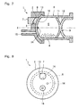
- FIG. 7 is a sectional view of a storage state of a chemicals mixing container according to a second embodiment of the invention.
- FIG. 8 is a front view of the chemicals mixing container of FIG. 7 ;
- FIG. 9 is a sectional view showing a step for use of the chemicals mixing container of FIG. 7 ;
- FIG. 10 is a sectional view of a storage state of a chemicals mixing container according to a third embodiment of the invention.
- FIG. 11 is a developed view of a rotation restricting structure of the chemicals mixing container of FIG. 10 .
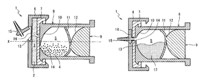
- FIG. 1 shows a chemicals mixing container 1 according to a first embodiment of the invention.
- the chemicals mixing container 1 isolates and stores therein two kinds of chemicals, particularly a powder material and a liquid material, for generating amalgam or other dental materials, bone cement or other medical materials and the like.
- the chemicals mixing container 1 can be used to mix the two kinds of chemicals and discharge (extrude) a desired mixture (or reaction product) as required.
- the chemicals mixing container 1 has a first internal space 3 for containing a liquid material 2 , and a second internal space 5 for containing a powder material 4 .
- the first internal space 3 is defined by a generally cylindrical-shaped first cylinder 6 and a generally disc-shaped first piston 7 fitted in the first cylinder 6 .
- the second internal space 5 is defined by a generally cylindrical-shaped second cylinder 8 connected to an outer side of the first piston 7 so as to be rotationally slidable thereon, and a second piston 9 fitted in the second cylinder 8 .
- the cylindrical portion of the second cylinder 8 has an end wall 10 which includes a flat outer wall surface serving as a sliding surface for the first piston 7 , and an inner wall surface that is curved to make the second internal space 5 swollen toward the first piston 7 .
- the second piston 9 is composed of an elastically-deformable, thin plate-shaped elastic partition wall portion 11 , and an auxiliary member portion 12 connected to an outer side of the elastic partition wall portion 11 .
- An outer peripheral portion of the elastic partition wall portion 11 is in air-tight sliding contact with the inner wall surface of the cylindrical portion of the second cylinder 8 over its entire periphery and is curved so as to make the second internal space 5 swollen toward a counter side of the first piston 7 .
- the auxiliary member portion 12 which has a convex shape conforming to the shape of the inner wall surface of the end wall 10 of the second cylinder 8 , is formed integrally with the elastic partition wall portion 11 .
- communicating holes 13 , 14 are formed at positions, respectively, which are eccentric by an equal distance from a rotation axis X of the rotational sliding surfaces.
- rotational positions of the first piston 7 and the second cylinder 8 are so determined that the communicating holes 13 and 14 are positionally different from each other as shown in FIG. 1 , thereby making the first internal space 3 and the second internal space 5 isolated from each other.
- the first cylinder 6 has, outside a wall of one end face thereof, a nozzle 15 formed in integrated connection.
- the nozzle 15 which swings against the first cylinder 6 , is fittable to a fitting recess 16 provided outside the end face of the first cylinder 6 .
- a protrusion of the nozzle 15 extends through a small-thickness bottom portion of the fitting recess 16 so that the first internal space 3 is opened to the outside via the nozzle 15 .
- the second cylinder 8 is rotated relative to the first piston 7 so that the communicating hole 13 of the first piston 7 and the communicating hole 14 of the second cylinder 8 communicate with each other.
- the chemicals mixing container 1 is well shaken to mix the liquid material 2 and the powder material 4 together.
- the end wall 10 of the second cylinder 8 and the elastic partition wall portion 11 of the second piston 9 are so shaped as to provide larger interior angles of corners of the second internal space 5 , so that the liquid material 2 and the powder material 4 are less likely to be accumulated. This facilitates an unevenness-free, uniform mixing of the liquid material 2 and the powder material 4 .
- the nozzle 15 is set in the fitting portion 16 so as to form an ejection path for a mixture (or reaction product) 17 of the liquid material 2 and the powder material 4 as shown in FIG. 4 . Then, as shown in FIG. 5 , pushing in the second piston 9 allows the mixture (or reaction product) 17 within the second internal space 5 to be extruded out through the nozzle 15 .
- the inner wall surface of the end wall 10 of the second cylinder 8 and the elastic partition wall portion 11 of the second piston 9 are curved in mutually counter directions. Therefore, as shown in FIG. 5 , the outer peripheral portion of the elastic partition wall portion 11 comes into contact with the inner wall surface of the end wall 10 before the second internal space 5 is completely compressed.
- the elastic partition wall portion is elastically deformable, further pushing in of the second piston 9 allows the elastic partition wall portion 11 to be warped in a reverse direction until the elastic partition wall portion 11 comes into contact with the auxiliary member portion 12 as shown in FIG. 6 .
- the auxiliary member portion 12 has a shape that conforms to the inner wall surface of the end wall 10 , the second piston 9 can make the second internal space 5 essentially zero in capacity as shown in the figure. That is, the mixture 17 resulting from mixing together the liquid material 2 and the powder material 4 is discharged via the nozzle 15 according to a pushed-in extent of the second piston 9 .
- the chemicals mixing container is able to store the two kinds of chemicals, the liquid material 2 and the powder material 4 , dividedly and in isolation in the first internal space 3 and the second internal space 5 , respectively, and to reliably mix together the liquid material 2 and the powder material 4 , as required, simply by rotating the second cylinder 8 relative to the first piston 7 so that the first internal space 3 and the second internal space 5 are communicated with each other easily and reliably.
- FIG. 7 shows a chemicals mixing container 1 according to a second embodiment of the invention. It is noted that in the following description, the same component members as those described above are designated by the same reference signs and their description is omitted.
- the second cylinder 8 is connected to the first cylinder 6 so as to be rotationally slidable on a spherical sliding surface.
- the first internal space 3 is smaller in diameter than the second internal space 5 and is eccentric relative to the rotation axis X of the first cylinder 6 and the second cylinder 8 .
- the first internal space 3 is fully opened to the second cylinder 8 , meaning that an aperture of the communicating hole 13 is equal to an inner diameter of the first cylinder 6 .
- the nozzle 15 is formed so as to be preliminarily opened to the sliding surface of the first cylinder 6 against the second cylinder 8 .
- FIG. 8 shows a state of the chemicals mixing container 1 of this embodiment as viewed from its front on the nozzle 15 side.
- the communicating hole 14 of the second cylinder 8 can be communicated with either the communicating hole 13 or the nozzle 15 depending on a rotational position of the second cylinder 8 relative to the first cylinder 6 .
- FIG. 10 shows a chemicals mixing container 1 according to a third embodiment of the invention.
- the first piston 7 is formed from an elastically deformable material into a cylindrical shape having an end wall 18 which makes sliding contact with the inner wall surface of the cylindrical portion of the first cylinder 6 to define the first internal space 3 .
- the second cylinder 8 is formed into a cylindrical shape having an end wall 19 which is fitted into the cylindrical portion of the first piston 7 and which makes sliding contact with the end wall 18 .
- the end wall 19 of the second cylinder 8 has a convex external shape conforming to the shape of the inner wall surface of the end wall 10 of the first cylinder 6 .
- communicating holes 13 , 14 are formed at positions, respectively, which are eccentric by an equal distance from the rotation axis X.
- a mis-operation preventing collar 20 for preventing mis-operations is fitted between an end portion of the first cylinder 6 and a flange of an end portion of the second piston 9 .
- the mis-operation preventing collar 20 is removable for use of the chemicals mixing container 1 .
- the nozzle 15 of this embodiment has a spherical body with a flow-through passage formed therein.
- the nozzle is held so as to be rotatable relative to the opening of the first cylinder 6 and serves as a ball valve which allows the flow-through passage to communicate with the opening or seals the opening by the spherical surface.
- the powder material 4 is contained in the first internal space 3 of the first cylinder 6
- the liquid material 2 is contained in the second internal space 5 of the second cylinder 8 .
- a guide groove 22 which receives a protrusion 21 provided at a portion of the outer periphery of the cylindrical portion of the first piston 7 so as to restrict a rotational position of the first piston 7 relative to the first cylinder 6 .
- a guide groove 24 which receives a protrusion 23 provided at a portion of the outer periphery of the cylindrical portion of the second cylinder 8 .
- a guide groove 26 which receives a protrusion 25 provided at a portion of the outer periphery of the cylindrical portion of the second piston 9 .
- FIG. 11 shows a developed view of the rotation restricting structure.
- Engagement between the protrusion 21 and the guide groove 22 restricts a rotational range of the first piston 7 relative to the first cylinder 6 , making it possible to push the first piston 7 inward of the first cylinder 6 only while the first piston 7 is in a specified rotational position.
- Engagement between the protrusion 23 and the guide groove 24 restricts a rotational range of the second cylinder 8 relative to the first piston 7 , making it possible to push the second cylinder 8 inward of the first piston 7 only while the second cylinder 8 is in a specified rotational position.
- FIG. 11 shows a rotation restricting structure of the chemicals mixing container 1 in a storage state before use.
- the protrusions 21 , 23 , 25 are restricted in their axial movement by the guide grooves 22 , 24 , 26 , respectively, the second piston 9 cannot be pushed into the first cylinder 6 even if the mis-operation preventing collar 20 is removed.
- a user rotates the second piston 9 counterclockwise relative to the first cylinder 6 .
- the protrusion 25 of the second piston 9 is moved to a left end (upper end in FIG. 11(C) ) of the guide groove 26 of the second cylinder 8 .
- the protrusion 25 makes the guide groove 26 rotated, causing the second cylinder 8 to be rotated counterclockwise relative to the first piston 7 .
- this rotation has caused the protrusion 23 to reach a left end (upper end in FIG.
- the user is enabled to push the second piston 9 into the first cylinder 6 .
- the protrusion 21 of the first piston 7 and the protrusion 23 of the second cylinder 8 are at the left ends of the guide groove 22 of the first cylinder 6 and the guide groove 24 of the first piston 7 , respectively, being prohibited from moving in the axial direction.
- the second piston 9 is enabled to be pushed in within the second cylinder 8 .
- the chemicals mixing container ensures a proper procedure of, after making the communicating hole 14 of the second cylinder 8 communicate with the communicating hole 13 of the first piston 7 , pushing the second piston 9 into the second cylinder 8 to compress the second internal space 5 so that the liquid material 2 is injected into the first internal space 3 .
- the second piston 9 cannot be rotated relative to the second cylinder 8 .
- the second cylinder 8 is rotated inside the first piston 7 to make the protrusion 23 move to a right end (lower end in FIG. 11(B) ) of the guide groove 24 .
- the communicating hole 13 of the first piston 7 and the communicating hole 14 of the second cylinder 8 are separated from each other.
- the first piston 7 is rotated inside the first cylinder 6 to make the protrusion 21 move to the right end (lower end in FIG. 11(A) ) of the guide groove 22 .
- the protrusion 21 and the protrusion 23 are allowed to move deeper (leftward in FIG. 11 ) in axial portions of the guide groove 22 and the guide groove 24 .
- An outer peripheral portion of the end wall 18 of the first piston 7 when coming into contact with the inner wall surface of the end wall of the first cylinder 6 , is elastically deformed by the end wall 19 of the second cylinder 8 to compress the remaining space of the first internal space 3 , thus allowing the mixture 17 to be completely discharged.
Landscapes
- Engineering & Computer Science (AREA)
- Mechanical Engineering (AREA)
- Dental Tools And Instruments Or Auxiliary Dental Instruments (AREA)
- Medical Preparation Storing Or Oral Administration Devices (AREA)
- Package Specialized In Special Use (AREA)
- Infusion, Injection, And Reservoir Apparatuses (AREA)
Applications Claiming Priority (1)
| Application Number | Priority Date | Filing Date | Title |
|---|---|---|---|
| PCT/JP2007/065961 WO2009022425A1 (fr) | 2007-08-16 | 2007-08-16 | Conteneur de mélange de médicaments avec des trous de communication excentriques |
Publications (2)
| Publication Number | Publication Date |
|---|---|
| US20110005945A1 US20110005945A1 (en) | 2011-01-13 |
| US8074794B2 true US8074794B2 (en) | 2011-12-13 |
Family
ID=40350489
Family Applications (1)
| Application Number | Title | Priority Date | Filing Date |
|---|---|---|---|
| US12/673,615 Expired - Fee Related US8074794B2 (en) | 2007-08-16 | 2007-08-16 | Chemicals mixing container with offset communicating holes |
Country Status (5)
| Country | Link |
|---|---|
| US (1) | US8074794B2 (fr) |
| JP (1) | JP5112438B2 (fr) |
| CN (1) | CN101778614B (fr) |
| DE (1) | DE112007003619B4 (fr) |
| WO (1) | WO2009022425A1 (fr) |
Cited By (2)
| Publication number | Priority date | Publication date | Assignee | Title |
|---|---|---|---|---|
| US20110056984A1 (en) * | 2009-09-08 | 2011-03-10 | Sdi (North America), Inc. | Mixing and dispensing container |
| US20160045283A1 (en) * | 2013-03-26 | 2016-02-18 | 3M Innovative Properties Company | A plunger assembly and a capsule for dispensing a dental material |
Families Citing this family (7)
| Publication number | Priority date | Publication date | Assignee | Title |
|---|---|---|---|---|
| BRPI1002819B1 (pt) * | 2010-01-25 | 2019-11-05 | Tecres Spa | dispositivo para preparar e administrar uma mistura de dois componentes |
| DE102010044141A1 (de) * | 2010-11-18 | 2012-05-24 | Raumedic Ag | Dosiervorrichtung |
| JP6267909B2 (ja) * | 2013-09-30 | 2018-01-24 | ぺんてる株式会社 | 液密構造の連通路を有する2成分混合容器 |
| JP6182039B2 (ja) * | 2013-09-30 | 2017-08-16 | ぺんてる株式会社 | バネ係合を利用したピストンを有する2成分混合容器 |
| JP6247491B2 (ja) | 2013-09-30 | 2017-12-13 | ぺんてる株式会社 | 混合容器のノズル取付け構造 |
| DE102016121606B4 (de) * | 2016-11-11 | 2019-05-02 | Heraeus Medical Gmbh | Knochenzementapplikator mit durch Knochenzementteig angetriebenem Verschlusssystem und Verfahren zum Applizieren eines Knochenzements |
| PL3998984T3 (pl) * | 2019-07-19 | 2023-07-31 | Septodont Ou Septodont Sas Ou Specialites Septodont | Kartridż do dozowania materiału |
Citations (17)
| Publication number | Priority date | Publication date | Assignee | Title |
|---|---|---|---|---|
| US4941751A (en) * | 1988-07-18 | 1990-07-17 | Muehlbauer Ernst | Multi-component mixing capsule having an ejection device for the mixed compound, in particular for dental purposes |
| US5026283A (en) * | 1986-08-08 | 1991-06-25 | G-C Dental Industrial Corporation | Capsules for tooth-restoring materials |
| USRE33801E (en) * | 1986-05-09 | 1992-01-21 | Dentsply Research & Development Corp. | Mixing and discharge capsule |
| JPH04329954A (ja) | 1991-04-30 | 1992-11-18 | Takeda Chem Ind Ltd | 個別密封容器に収容した2種薬剤の無菌保持混合装置 |
| US5172807A (en) * | 1991-09-30 | 1992-12-22 | Centrix, Inc. | Cement mixing capsule |
| WO1994012227A1 (fr) | 1992-12-01 | 1994-06-09 | Tetsuro Higashikawa | Seringue |
| JPH08206197A (ja) | 1995-02-03 | 1996-08-13 | Material Eng Tech Lab Inc | 注射器 |
| WO2000010479A1 (fr) | 1998-08-19 | 2000-03-02 | Dentsply International Inc. | Capsule de melange/distribution |
| WO2000023002A1 (fr) | 1998-10-19 | 2000-04-27 | Dentsply International Inc. | Capsule de melange/distribution |
| US20010053511A1 (en) * | 2000-05-31 | 2001-12-20 | Gc Corporation | Capsule for dental restoration material |
| US6375460B1 (en) * | 2000-02-17 | 2002-04-23 | Voco Gmbh | Capsule for mixing and applying dental cement |
| US6386872B1 (en) * | 2001-01-03 | 2002-05-14 | Gc Corporation | Capsule for dental restoration material |
| JP2004041377A (ja) | 2002-07-10 | 2004-02-12 | Shionogi & Co Ltd | 輸液容器及び薬剤収容器 |
| JP2004041568A (ja) | 2002-07-15 | 2004-02-12 | Nipro Corp | 2成分混合型プレフィルドシリンジ |
| JP2007061633A (ja) | 2005-09-01 | 2007-03-15 | Three M Innovative Properties Co | 貯蔵、混合および分注するためのカプセル |
| US7311195B2 (en) * | 2001-10-01 | 2007-12-25 | Alfred Schmid Ag Gossau | Mixing capsule and method for activating the same |
| JP4329954B2 (ja) | 1999-06-29 | 2009-09-09 | 東洋ゴム工業株式会社 | 空気入りタイヤ |
Family Cites Families (2)
| Publication number | Priority date | Publication date | Assignee | Title |
|---|---|---|---|---|
| JPH0529718Y2 (fr) * | 1987-06-22 | 1993-07-29 | ||
| JP4152104B2 (ja) * | 2001-12-28 | 2008-09-17 | テルモ株式会社 | シリンジおよびガスケット |
-
2007
- 2007-08-16 US US12/673,615 patent/US8074794B2/en not_active Expired - Fee Related
- 2007-08-16 JP JP2009528013A patent/JP5112438B2/ja not_active Expired - Fee Related
- 2007-08-16 WO PCT/JP2007/065961 patent/WO2009022425A1/fr not_active Ceased
- 2007-08-16 CN CN2007801002394A patent/CN101778614B/zh not_active Expired - Fee Related
- 2007-08-16 DE DE112007003619.2T patent/DE112007003619B4/de not_active Expired - Fee Related
Patent Citations (23)
| Publication number | Priority date | Publication date | Assignee | Title |
|---|---|---|---|---|
| USRE33801E (en) * | 1986-05-09 | 1992-01-21 | Dentsply Research & Development Corp. | Mixing and discharge capsule |
| US5026283A (en) * | 1986-08-08 | 1991-06-25 | G-C Dental Industrial Corporation | Capsules for tooth-restoring materials |
| US4941751A (en) * | 1988-07-18 | 1990-07-17 | Muehlbauer Ernst | Multi-component mixing capsule having an ejection device for the mixed compound, in particular for dental purposes |
| JPH04329954A (ja) | 1991-04-30 | 1992-11-18 | Takeda Chem Ind Ltd | 個別密封容器に収容した2種薬剤の無菌保持混合装置 |
| US5172807A (en) * | 1991-09-30 | 1992-12-22 | Centrix, Inc. | Cement mixing capsule |
| WO1994012227A1 (fr) | 1992-12-01 | 1994-06-09 | Tetsuro Higashikawa | Seringue |
| EP0695555A1 (fr) | 1992-12-01 | 1996-02-07 | HIGASHIKAWA, Tetsuro | Seringue |
| US5599312A (en) | 1992-12-01 | 1997-02-04 | Higashikawa; Tetsuro | Syringe |
| JPH08206197A (ja) | 1995-02-03 | 1996-08-13 | Material Eng Tech Lab Inc | 注射器 |
| JP2002523132A (ja) | 1998-08-19 | 2002-07-30 | デンツプライ インターナショナル インコーポレーテッド | 混合及び投薬カプセル |
| WO2000010479A1 (fr) | 1998-08-19 | 2000-03-02 | Dentsply International Inc. | Capsule de melange/distribution |
| WO2000023002A1 (fr) | 1998-10-19 | 2000-04-27 | Dentsply International Inc. | Capsule de melange/distribution |
| JP2003522555A (ja) | 1998-10-19 | 2003-07-29 | デンツプライ インターナショナル インコーポレーテッド | 混合および吐出用カプセル |
| JP4329954B2 (ja) | 1999-06-29 | 2009-09-09 | 東洋ゴム工業株式会社 | 空気入りタイヤ |
| US6375460B1 (en) * | 2000-02-17 | 2002-04-23 | Voco Gmbh | Capsule for mixing and applying dental cement |
| US20010053511A1 (en) * | 2000-05-31 | 2001-12-20 | Gc Corporation | Capsule for dental restoration material |
| US6682347B2 (en) * | 2000-05-31 | 2004-01-27 | Gc Corporation | Capsule for dental restoration material |
| US6869284B2 (en) * | 2000-05-31 | 2005-03-22 | Gc Corporation | Capsule for dental restoration material |
| US6386872B1 (en) * | 2001-01-03 | 2002-05-14 | Gc Corporation | Capsule for dental restoration material |
| US7311195B2 (en) * | 2001-10-01 | 2007-12-25 | Alfred Schmid Ag Gossau | Mixing capsule and method for activating the same |
| JP2004041377A (ja) | 2002-07-10 | 2004-02-12 | Shionogi & Co Ltd | 輸液容器及び薬剤収容器 |
| JP2004041568A (ja) | 2002-07-15 | 2004-02-12 | Nipro Corp | 2成分混合型プレフィルドシリンジ |
| JP2007061633A (ja) | 2005-09-01 | 2007-03-15 | Three M Innovative Properties Co | 貯蔵、混合および分注するためのカプセル |
Non-Patent Citations (2)
| Title |
|---|
| International Search Report issued Oct. 16, 2007 in International (PCT) Application No. PCT/JP2007/065961. |
| Patent Cooperation Treaty (PCT) International Preliminary Report on Patentability issued Mar. 9, 2010 in corresponding to International Application No. PCT/JP2007/065961. |
Cited By (4)
| Publication number | Priority date | Publication date | Assignee | Title |
|---|---|---|---|---|
| US20110056984A1 (en) * | 2009-09-08 | 2011-03-10 | Sdi (North America), Inc. | Mixing and dispensing container |
| US8893925B2 (en) * | 2009-09-08 | 2014-11-25 | Sdi (North America), Inc. | Mixing and dispensing container |
| US20160045283A1 (en) * | 2013-03-26 | 2016-02-18 | 3M Innovative Properties Company | A plunger assembly and a capsule for dispensing a dental material |
| US10117726B2 (en) * | 2013-03-26 | 2018-11-06 | 3M Innovative Properties Company | Plunger assembly and a capsule for dispensing a dental material |
Also Published As
| Publication number | Publication date |
|---|---|
| US20110005945A1 (en) | 2011-01-13 |
| CN101778614A (zh) | 2010-07-14 |
| DE112007003619B4 (de) | 2015-09-10 |
| CN101778614B (zh) | 2012-11-28 |
| DE112007003619T5 (de) | 2010-09-09 |
| JPWO2009022425A1 (ja) | 2010-11-11 |
| WO2009022425A1 (fr) | 2009-02-19 |
| JP5112438B2 (ja) | 2013-01-09 |
Similar Documents
| Publication | Publication Date | Title |
|---|---|---|
| US8403180B2 (en) | Chemicals mixing container with elastic partition wall | |
| US8074794B2 (en) | Chemicals mixing container with offset communicating holes | |
| KR100593246B1 (ko) | 용기 | |
| KR101069449B1 (ko) | 멀티 격실 컨테이너 조립체 시스템 | |
| US10874188B2 (en) | Filling assembly for the manufacturing of a packaging and dispensing device for dual content | |
| JPWO2010122981A1 (ja) | 用時混合容器 | |
| JP6759344B2 (ja) | 2つの内容物用の包装吐出装置 | |
| WO2010114101A1 (fr) | Conteneur de mélange de pré-utilisation | |
| CN1964895A (zh) | 多隔间容器组件的套筒单元 | |
| JPH11227774A (ja) | 二種混合容器 | |
| US20210002058A1 (en) | System for packaging two components | |
| CN102802812B (zh) | 用于单次使用的多组分存储筒 | |
| JP2013154915A (ja) | 容器 | |
| KR101884287B1 (ko) | 동결 건조 타입 듀얼 믹싱용기 | |
| KR101883730B1 (ko) | 듀얼 믹싱용기 | |
| US20240336409A1 (en) | Content container | |
| JPH0796978A (ja) | 分離収納及び混合使用兼用容器 | |
| KR101477332B1 (ko) | 복수의 재료들을 혼합하고 배출하는 장치 | |
| JP6416004B2 (ja) | 粉体投与容器 | |
| CN219216031U (zh) | 一种旋压式混合腔体装置 | |
| JPH0796979A (ja) | 隔離収納及び混合使用兼用容器 | |
| KR20230174891A (ko) | 이종 내용물 혼합 구조를 갖는 화장품 용기 | |
| KR200487556Y1 (ko) | 포장 용기 | |
| KR20100099481A (ko) | 주사기의 이종 약액 혼합 밸브장치 | |
| JP2007314223A (ja) | 用時混合容器 |
Legal Events
| Date | Code | Title | Description |
|---|---|---|---|
| AS | Assignment |
Owner name: KABUSHIKI KAISHA SHOFU, JAPAN Free format text: ASSIGNMENT OF ASSIGNORS INTEREST;ASSIGNORS:NAKATSUKA, TOSHIYUKI;KADOBAYASHI, YUSEI;TAKANO, SATOSHI;SIGNING DATES FROM 20090731 TO 20090813;REEL/FRAME:023939/0920 |
|
| ZAAA | Notice of allowance and fees due |
Free format text: ORIGINAL CODE: NOA |
|
| ZAAB | Notice of allowance mailed |
Free format text: ORIGINAL CODE: MN/=. |
|
| STCF | Information on status: patent grant |
Free format text: PATENTED CASE |
|
| FPAY | Fee payment |
Year of fee payment: 4 |
|
| MAFP | Maintenance fee payment |
Free format text: PAYMENT OF MAINTENANCE FEE, 8TH YEAR, LARGE ENTITY (ORIGINAL EVENT CODE: M1552); ENTITY STATUS OF PATENT OWNER: LARGE ENTITY Year of fee payment: 8 |
|
| FEPP | Fee payment procedure |
Free format text: MAINTENANCE FEE REMINDER MAILED (ORIGINAL EVENT CODE: REM.); ENTITY STATUS OF PATENT OWNER: LARGE ENTITY |
|
| LAPS | Lapse for failure to pay maintenance fees |
Free format text: PATENT EXPIRED FOR FAILURE TO PAY MAINTENANCE FEES (ORIGINAL EVENT CODE: EXP.); ENTITY STATUS OF PATENT OWNER: LARGE ENTITY |
|
| STCH | Information on status: patent discontinuation |
Free format text: PATENT EXPIRED DUE TO NONPAYMENT OF MAINTENANCE FEES UNDER 37 CFR 1.362 |
|
| FP | Lapsed due to failure to pay maintenance fee |
Effective date: 20231213 |