US8091613B2 - Thermal energy storage materials - Google Patents
Thermal energy storage materials Download PDFInfo
- Publication number
- US8091613B2 US8091613B2 US12/389,416 US38941609A US8091613B2 US 8091613 B2 US8091613 B2 US 8091613B2 US 38941609 A US38941609 A US 38941609A US 8091613 B2 US8091613 B2 US 8091613B2
- Authority
- US
- United States
- Prior art keywords
- thermal energy
- energy storage
- storage material
- heat
- temperature
- Prior art date
- Legal status (The legal status is an assumption and is not a legal conclusion. Google has not performed a legal analysis and makes no representation as to the accuracy of the status listed.)
- Expired - Fee Related, expires
Links
Images


Classifications
-
- F—MECHANICAL ENGINEERING; LIGHTING; HEATING; WEAPONS; BLASTING
- F28—HEAT EXCHANGE IN GENERAL
- F28D—HEAT-EXCHANGE APPARATUS, NOT PROVIDED FOR IN ANOTHER SUBCLASS, IN WHICH THE HEAT-EXCHANGE MEDIA DO NOT COME INTO DIRECT CONTACT
- F28D20/00—Heat storage plants or apparatus in general; Regenerative heat-exchange apparatus not covered by groups F28D17/00 or F28D19/00
- F28D20/02—Heat storage plants or apparatus in general; Regenerative heat-exchange apparatus not covered by groups F28D17/00 or F28D19/00 using latent heat
- F28D20/021—Heat storage plants or apparatus in general; Regenerative heat-exchange apparatus not covered by groups F28D17/00 or F28D19/00 using latent heat the latent heat storage material and the heat-exchanging means being enclosed in one container
-
- C—CHEMISTRY; METALLURGY
- C09—DYES; PAINTS; POLISHES; NATURAL RESINS; ADHESIVES; COMPOSITIONS NOT OTHERWISE PROVIDED FOR; APPLICATIONS OF MATERIALS NOT OTHERWISE PROVIDED FOR
- C09K—MATERIALS FOR MISCELLANEOUS APPLICATIONS, NOT PROVIDED FOR ELSEWHERE
- C09K5/00—Heat-transfer, heat-exchange or heat-storage materials, e.g. refrigerants; Materials for the production of heat or cold by chemical reactions other than by combustion
- C09K5/02—Materials undergoing a change of physical state when used
- C09K5/06—Materials undergoing a change of physical state when used the change of state being from liquid to solid or vice versa
- C09K5/063—Materials absorbing or liberating heat during crystallisation; Heat storage materials
-
- F—MECHANICAL ENGINEERING; LIGHTING; HEATING; WEAPONS; BLASTING
- F24—HEATING; RANGES; VENTILATING
- F24H—FLUID HEATERS, e.g. WATER OR AIR HEATERS, HAVING HEAT-GENERATING MEANS, e.g. HEAT PUMPS, IN GENERAL
- F24H7/00—Storage heaters, i.e. heaters in which the energy is stored as heat in masses for subsequent release
- F24H7/02—Storage heaters, i.e. heaters in which the energy is stored as heat in masses for subsequent release the released heat being conveyed to a transfer fluid
-
- F—MECHANICAL ENGINEERING; LIGHTING; HEATING; WEAPONS; BLASTING
- F28—HEAT EXCHANGE IN GENERAL
- F28D—HEAT-EXCHANGE APPARATUS, NOT PROVIDED FOR IN ANOTHER SUBCLASS, IN WHICH THE HEAT-EXCHANGE MEDIA DO NOT COME INTO DIRECT CONTACT
- F28D9/00—Heat-exchange apparatus having stationary plate-like or laminated conduit assemblies for both heat-exchange media, the media being in contact with different sides of a conduit wall
- F28D9/0031—Heat-exchange apparatus having stationary plate-like or laminated conduit assemblies for both heat-exchange media, the media being in contact with different sides of a conduit wall the conduits for one heat-exchange medium being formed by paired plates touching each other
-
- F—MECHANICAL ENGINEERING; LIGHTING; HEATING; WEAPONS; BLASTING
- F28—HEAT EXCHANGE IN GENERAL
- F28D—HEAT-EXCHANGE APPARATUS, NOT PROVIDED FOR IN ANOTHER SUBCLASS, IN WHICH THE HEAT-EXCHANGE MEDIA DO NOT COME INTO DIRECT CONTACT
- F28D20/00—Heat storage plants or apparatus in general; Regenerative heat-exchange apparatus not covered by groups F28D17/00 or F28D19/00
- F28D2020/0004—Particular heat storage apparatus
- F28D2020/0008—Particular heat storage apparatus the heat storage material being enclosed in plate-like or laminated elements, e.g. in plates having internal compartments
-
- F—MECHANICAL ENGINEERING; LIGHTING; HEATING; WEAPONS; BLASTING
- F28—HEAT EXCHANGE IN GENERAL
- F28F—DETAILS OF HEAT-EXCHANGE AND HEAT-TRANSFER APPARATUS, OF GENERAL APPLICATION
- F28F2240/00—Spacing means
-
- F—MECHANICAL ENGINEERING; LIGHTING; HEATING; WEAPONS; BLASTING
- F28—HEAT EXCHANGE IN GENERAL
- F28F—DETAILS OF HEAT-EXCHANGE AND HEAT-TRANSFER APPARATUS, OF GENERAL APPLICATION
- F28F9/00—Casings; Header boxes; Auxiliary supports for elements; Auxiliary members within casings
- F28F9/02—Header boxes; End plates
- F28F9/026—Header boxes; End plates with static flow control means, e.g. with means for uniformly distributing heat exchange media into conduits
-
- Y—GENERAL TAGGING OF NEW TECHNOLOGICAL DEVELOPMENTS; GENERAL TAGGING OF CROSS-SECTIONAL TECHNOLOGIES SPANNING OVER SEVERAL SECTIONS OF THE IPC; TECHNICAL SUBJECTS COVERED BY FORMER USPC CROSS-REFERENCE ART COLLECTIONS [XRACs] AND DIGESTS
- Y02—TECHNOLOGIES OR APPLICATIONS FOR MITIGATION OR ADAPTATION AGAINST CLIMATE CHANGE
- Y02E—REDUCTION OF GREENHOUSE GAS [GHG] EMISSIONS, RELATED TO ENERGY GENERATION, TRANSMISSION OR DISTRIBUTION
- Y02E60/00—Enabling technologies; Technologies with a potential or indirect contribution to GHG emissions mitigation
- Y02E60/14—Thermal energy storage
-
- Y—GENERAL TAGGING OF NEW TECHNOLOGICAL DEVELOPMENTS; GENERAL TAGGING OF CROSS-SECTIONAL TECHNOLOGIES SPANNING OVER SEVERAL SECTIONS OF THE IPC; TECHNICAL SUBJECTS COVERED BY FORMER USPC CROSS-REFERENCE ART COLLECTIONS [XRACs] AND DIGESTS
- Y10—TECHNICAL SUBJECTS COVERED BY FORMER USPC
- Y10T—TECHNICAL SUBJECTS COVERED BY FORMER US CLASSIFICATION
- Y10T29/00—Metal working
- Y10T29/49—Method of mechanical manufacture
- Y10T29/4935—Heat exchanger or boiler making
- Y10T29/49357—Regenerator or recuperator making
Definitions
- the present invention relates to thermal energy storage materials (TESMs), and in one particular aspect, to improved TESM chemical compositions.
- Thermal energy storage materials are known and have been used in applications for storing heat for subsequent use.
- Many TESMs are phase change materials, meaning they undergo a phase change, typically between solid state and liquid state, and can store (or release) a considerable amount of the heat, regarded as latent heat from the phase change.
- Many of these phase change materials include mixtures of compounds, such that the mixture has a lower liquidus temperature than the pure compounds or elements used in the mixture. See generally, Chapter 3, I. Dincer and M. A. Rosen, Thermal Energy Storage Systems and Applications , John Wiley & Sons, London, 2002.
- TESMs for use at temperatures below about 85° C.
- Much of this body of work utilizes mixtures of hydrous metal salts.
- U.S. Pat. No. 6,627,106 discloses various phase change materials comprising ternary mixtures of magnesium nitrate hexahydrate with other metal nitrates. These mixtures having phase changes from about 52° C. to about 69° C., depending on the metal nitrates being combined and on the concentration of each metal salt.
- U.S. Pat. No. 5,785,884 discloses similar ternary mixtures of magnesium nitrate hexahydrate with sodium nitrate and potassium nitrate.
- phase change materials comprising a mixture of two metal nitrates (an alkali metal nitrate and an alkaline earth metal nitrate) with an excess of water, such that the phase change material has a small change in density between the solid phase and the liquid phase.
- the water concentration ranges from 27.9% to 37.2% by weight of the phase change material, with the specific concentration range of the water dependent on the metal salts being mixed.
- U.S. Pat. No. 5,348,080 shows mixtures of water, sodium nitrate, and potassium nitrate and describes phase change materials having a solid to liquid transition temperature below 0° C. See also, U.S. Pat. No. 5,591,374.
- TESM may be known to have certain attributes to qualify it as a heat storage material
- the assembly of such TESMs into a functionally operative system has been complicated by the unpredictability of the materials and other considerations, such as TESM interactions in service with other system materials.
- corrosion resistance has proven to be a complicating factor for some systems.
- Many materials known to be phase change materials are also corrosive in many environments. It may also prove difficult to predict how mixtures of such materials will fare in a desired application.
- the TESMs must be packaged in some device that affords efficient heat exchange.
- the present invention meets some or all of the above needs by providing an improved TESM system that reliably and reproducibly stores and recovers latent heat comprising: a container having a wall surface; and a TESM in at least partial contact with the wall surface, and including: i) at least one first metal containing material including at least one first metal compound that includes a nitrate ion, a nitrite ion, or both; ii) at least one second metal containing material including at least one second metal compound; and iii) optionally including water, wherein the water concentration if any is present is less than about 10 wt. %; wherein the TESM has a liquidus temperature, T L , from about 100° C.
- the TESM exhibits a heat storage density from 300° C. to 80° C. of at least about 1 MJ/l; so that upon being used in a system that generates heat, at least a portion of the heat is captured and stored by the TESM and subsequently released for use, and wherein the absolute value of the change in mass of the wall surface in contact with the TESM is less than about 1 g per m 2 of the wall surface after 45 days exposure to the TESM at 300° C. in an inert atmosphere.
- the TESM system may include a TESM according to the present teachings in a container (e.g., a capsule), optionally being substantially free of any water and/or hydrogen in some other form, which has an interior wall including a metal oxide that has substantially no thermodynamic reaction with the TESM in service conditions.
- a container e.g., a capsule
- One particularly preferred TESM includes two metal containing compounds, each including a cation selected from lithium or sodium, and an anion selected from nitrate or nitrite.
- the TESM may include one or more other agents that improve its performance, such as a thermal conductivity promoter, a corrosion inhibitor, a nucleator, or any combination thereof.
- the TESMs exhibit any of a number of other attractive characteristics.
- the TESM may have a value of H c50 /H C1 greater than 70%, where H c50 is defined as the quenched heat of crystallization measured by differential scanning calorimetry at a cooling rate of about 50° C./min over a temperature range of T L +50° C. to T L ⁇ 100° C. and H C1 is defined as the slow cooled heat of crystallization measured by differential scanning calorimetry at a cooling rate of about 1° C./min.
- the TESM may have a liquidus temperature which is less than T min ⁇ 25° C., wherein T min is the lowest melting temperature of any binary salt which can be formed by any anion of the TESM and any cation of the TESM.
- T min is the lowest melting temperature of any binary salt which can be formed by any anion of the TESM and any cation of the TESM.
- FIG. 1 is a calculated phase diagram of a lithium fluoride and lithium nitrate system.
- FIG. 2 is an expected experimental phase diagram of a lithium nitrate and lithium hydroxide system.
- FIG. 3 illustrates output of a test for measuring the heat storage density from 300° C. to 80° C. and the cumulative heat density from 80° C. to 300° C.
- FIG. 4 illustrates the concepts of sensible and latent heat of a TESM.
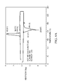
- FIG. 5A illustrates a plot of crystallization curves of an illustrative TESM within the present teaching for its 1st, 51st and 101st cycles from about 20° C. to about 320° C.
- FIG. 5B illustrates the variation in the heat storage density from 320° C. to 20° C. for an illustrative TESM as a function of the number of cycles between 20° C. and 320° C.
- FIG. 5C plots cumulative heat as a function of temperature for an illustrative TESM.
- FIGS. 6A and 6B illustrate the thermal properties of a TESM before and after temperature cycles to about 500° C.
- FIG. 7A illustrates crystallization curves of an illustrative TESM within the present teaching for its 1st, 51st and 101st cycles from about 40° C. to about 305° C.
- FIG. 7B illustrates a plot of the variation in the heat storage density from 305° C. to 40° C. for an illustrative TESM as a function of the number of cycles between 40° C. and 305° C.
- FIG. 7C plots cumulative heat as a function of temperature for an illustrative TESM.
- FIGS. 8A and 8B illustrate the thermal properties of a TESM before and after temperature cycles to about 500° C.
- FIG. 9A illustrates crystallization curves of an illustrative TESM within the present teaching for its 1st, 51st and 101st cycles from about 25° C. to about 200° C.
- FIG. 9B illustrates a plot of the variation in the heat storage density from 200° C. to 25° C. for an illustrative TESM as a function of the number of cycles between 25° C. and 200° C.
- FIG. 9C plots cumulative heat as a function of temperature for an illustrative TESM.
- FIG. 10 illustrates the hysteresis of the thermal storage density for a TESM material having low hysteresis and a TESM having high hysteresis.
- FIGS. 11A , 11 B, and 11 C illustrates the melting and crystallization characteristics of erythritol during the first, second and third heating and cooling cycles, respectively.
- FIG. 12 illustrates a cross-section of a diffusion bonded assembly of two plies having an array of capsules containing a thermal energy storage material (e.g. a blister pack).
- a thermal energy storage material e.g. a blister pack
- the teachings herein pertain generally to thermal energy storage materials (TESMs).
- the TESMs offer a number of valuable attributes that render them useful in various applications in which it is desired to store heat, and later to release the heat after a lapse of some amount of time.
- the present TESMs will preferably be phase change materials, in that they undergo at least one phase change at a temperature below their maximum operating storage temperature for a given application.
- Such a phase change can be a solid-solid phase change, a solid-liquid phase change, or a liquid-gas phase change.
- One preferred phase change is a solid-liquid phase change, pursuant to which energy equal to the latent heat of fusion is required to melt the material.
- the solidus temperature is the temperature below which a given material, at thermodynamic equilibrium, is completely solid.
- the liquidus temperature is the temperature above which a given material, at thermodynamic equilibrium, is completely liquid.
- the melting temperature or the eutectic temperature (T e )
- Such temperature is, theoretically, the temperature above which the material is liquid and below which the material is solid.
- melting temperatures, liquidus temperatures or solidus temperatures are at approximately one (1) atmosphere pressure.
- Metal containing compounds which are mixtures of metals or mixtures of metal salts may have a eutectic composition.
- the mixture When the mixture has a composition which is not at a eutectic composition, it will typically undergo a phase transition over a range of temperatures. For example, the mixture may start to melt at the solidus temperature, T s which may be the eutectic temperature. As the temperature increases, the mixture will continue to melt until it reaches the liquidus temperature, T L . Above the liquidus temperature the mixture is completely in the liquid (molten) state.
- the solidus and liquidus temperatures can be determined by measurements using differential scanning calorimetry.
- the present teachings contemplate that they are determined by differential scanning calorimetry by heating a 3.0-4.0 mg sample from room temperature at a rate of about 10° C./min.
- these values can be realized by use of a differential scanning calorimeter (e.g., a Q2000 differential scanning calorimeter (TA Instruments, New Castle, Del.)) at a scanning rate of about 10° C./minute, heated to a temperature beyond which no liquid remains in the sample (e.g., to about 400° C.), and plotting heat flux against temperature, establishing a base line value, and identifying deviations from the baseline. As temperature is increased, the start of the deviation corresponds with the solidus, and the end of the deviation corresponds with the liquidus.
- a calculated equilibrium phase diagram (at 1 atm) of lithium fluoride and lithium nitrate (given in FIG. 1 ) can be used to illustrate these concepts.
- the solidus line for this composition shown by line S, is a horizontal line and gives the predicted solidus temperature.
- One of the liquidus lines is shown by line L. This liquidus line corresponds to the concentration dependent liquidus temperature of the compositions containing less than about 95.3 mole % lithium nitrate.
- Lithium fluoride and lithium nitrate are seen to have a eutectic composition, shown by point E, of about 95.3 mole % lithium nitrate and about 4.7 mole % lithium fluoride, with a eutectic temperature of about 250° C., which is below the melting temperature of either pure lithium nitrate or pure lithium fluoride.
- point E a eutectic composition
- material having the eutectic composition When material having the eutectic composition is heated from room temperature, it will start as a solid phase and undergo a phase transition at about 250° C. where the material will completely melt at that temperature.
- This theoretical phase diagram can be further understood by points P 1 , P 2 , P 3 , P 4 , and P 5 , which all correspond to a composition of about 80 mole % lithium nitrate.
- Point P 1 is located below the solidus line and shows a condition where, at equilibrium, the material is expected to exist only in the solid state.
- Point P 2 is on the solidus line.
- Point P 3 is between the solidus line and the liquidus line and shows a condition where, at equilibrium, the material is expected to have both a liquid phase and a solid phase.
- Point P 4 is on the liquidus line.
- Point P 5 is above the liquidus line and shows a condition where, at equilibrium, the material is expected to exist only in the liquid phase.
- a calculated phase diagram of lithium nitrate and lithium hydroxide (given in FIG. 2 ) further illustrates these concepts.
- These salts have a eutectic composition of about 0.393 mole fraction lithium hydroxide, and a eutectic temperature of about 186° C. which is more than 50° C. lower than the melting temperature of pure lithium nitrate.
- a mixture of salts may have a large range of compositions which have a liquidus temperature lower than (e.g., at least 25° C., or even at least 50° C.) one or all of the pure salts in the mixture.
- the present invention contemplates that the TESM include (or may even consist essentially of or consist of) at least one first metal containing material, and more preferably a combination of the at least one first metal containing material and at least one second metal containing material.
- the first metal containing material, the second metal containing material, or both may be a substantially pure metal, an alloy such as one including a substantially pure metal and one or more additional alloying ingredients (e.g., one or more other metals), an intermetallic, a metal compound (e.g., a salt, an oxide or otherwise), or any combination thereof.
- One preferred approach is to employ one or more metal containing materials as part of a metal compound; a more preferred approach is to employ a mixture of at least two metal compounds.
- a suitable metal compound may be selected from oxides, hydroxides, compounds including nitrogen and oxygen (e.g., nitrates, nitrites or both), halides, or any combination thereof.
- One particularly preferred metal compound includes at least one nitrate compound, at least one nitrite compound or a combination thereof.
- Preferred TESMs for use herein thus may be part of a binary component material system, pursuant to which two discrete compounds are combined with each other (e.g., a first metal nitrate or nitrite combined with second metal nitrate or nitrite). It is possible that ternary, quaternary or other multiple component material systems may be employed also.
- the TESMs herein may be mixtures of two or more materials that exhibit a eutectic.
- the metals for use herein may be any suitable metal capable of being used in a material system that has a liquidus temperature from about 85° C. to about 350° C.
- suitable metals may be selected from tin, lead, zinc, magnesium, aluminum, lithium, sodium, potassium, beryllium, calcium, gallium, indium, thallium, strontium, barium, rubidium, francium, bismuth, cadmium, antimony, tellurium, or any combination thereof.
- Still more preferred metals are selected from sodium, potassium, lithium, magnesium, or any combination thereof.
- Even still more preferred metals are sodium, lithium, potassium, or any combination thereof. Most preferred are sodium, lithium or a combination thereof. It will be appreciated from the above, that certain of the mentioned metals have melting points outside of the range of about 85° C. to about 350° C.; such a metal is contemplated to be employed other than in its pure form.
- the liquidus temperature of the TESMs may be low relative to the melting temperatures of the individual components in the TESMs.
- the TESMs may have a liquidus temperature less than about T min ⁇ 25° C., where T min is the lowest melting temperature of any salt (e.g., a binary compound salt) which can be formed by a significant anion (e.g., an anion present at a concentration of at least about 3 mole %, based on the total moles of anions in the TESM) and a significant cation (e.g., a cation present at a concentration of at least about 3 mole %, based on the total moles of cations in the TESM) of the TESMs.
- any salt e.g., a binary compound salt
- the TESMs may have a liquidus temperature which more preferably is less than about T min ⁇ 40° C., and most preferably is less than about T min ⁇ 50° C.
- the liquidus temperature of the TESMs may also be characterized in relation to the minimum liquidus temperature of all the composition comprising the anions and cations (e.g., comprising the significant anions and cations) in the TESMs, T liquidus,min .
- T liquidus,min may be the eutectic temperature.
- the TESMs may have a liquidus temperature less than about T liquidus,min +50° C., more preferably less than about T liquidus,min +25° C., and most preferably less than about T liquidus,min +10° C.
- Thermal energy storage materials which are useful for the present invention may have a liquidus temperature from about 85° C. to about 350° C., such as about 95° C. to about 300° C. (e.g., from about 100° C. to about 200° C.).
- the liquidus temperature is preferably less than about 350° C., more preferably less than about 310° C. (e.g. less than about 300° C., or even 270° C.).
- Thermal energy storage materials having a liquidus temperature less than about 250° C. are also contemplated.
- the liquidus temperature is preferably greater than about 95° C., more preferably greater than about 100° C. (e.g. greater than about 125° C., or even 175° C.). Higher liquidus temperatures may be possible also (e.g., to about 700° C.).
- One or more materials that have a liquidus temperature that exceeds about 200° C.
- One or more of the metal containing materials may have a liquidus temperature less than about 450° C. and, more preferably, less than about 400° C., or even less than about 350° C.
- a composition herein may include at least a first metal compound and a second metal compound. At least one of the compounds (e.g., the first metal compound) may have a liquidus temperature, T L less than about 450° C. and more preferably, less than about 400° C., still more preferably less than about 350° C. (e.g. less than about 310° C.).
- the first metal compound may also have a liquidus temperature higher than about 85° C., and more preferably, higher than about 90° C., still more preferably higher than about 100° C., (e.g. higher than about 125° C., or even 175° C.).
- one of the metal containing compounds preferably has a liquidus temperature higher than the liquidus temperature of the other (e.g., the first) metal containing compound.
- One (e.g., the second) metal containing compound may have a larger entropy of fusion density than the other (e.g., the first) metal containing compound.
- the second metal containing compound may have a liquidus temperature, T L , greater than about 310° C. and more preferably, greater than about 400° C., (e.g. greater than about 440° C.).
- the difference between the liquidus temperature and the solidus temperature is preferably less than about 150° C., more preferably less than about 100° C., and most preferably less than about 50° C.
- solidus temperatures may range from about 85° C. to about 350° C.
- the solidus temperature may be less than about 300° C., more preferably less than about 270° C. (e.g. less than about 250° C.).
- the solidus temperature may be greater than about 100° C., more preferably greater than about 125° C. (e.g. greater than about 175° C.).
- the solidus temperature may be from about 100° C. to about 300° C.
- the TESMs systems employing them herein will be essentially free of water, whether chemical water (e.g., chemically bound water), physical water (e.g., physically bound water) or both (i.e., it will be substantially anhydrous).
- chemical water e.g., chemically bound water
- physical water e.g., physically bound water
- both i.e., it will be substantially anhydrous
- the TESM or system that employs the TESM may have a concentration of water, measured for example by Karl Fischer titration (e.g., using a Sartorius WDS 400) less than about 5000 ppm, 2500 ppm, 1000 ppm, 500 ppm, 400 ppm, 350 ppm, 250 ppm, 100 ppm, 50 ppm, 25 ppm, 10 ppm, or even below the detection limit of typical Karl Fisher titration techniques using a sample size of about 1 gram.
- Karl Fischer titration e.g., using a Sartorius WDS 400
- water optionally may be employed in TESMs of the present invention, such as water as a result of hydration of a metal salt, by the addition of water as a diluent, or otherwise.
- water may be present in an amount less than about 10 percent by weight of the total material in the thermal energy storage material system, more preferably less than about 5 percent by weight of the total material in the thermal energy storage material system, and still more preferably less than about 2 percent by weight of the total material in the thermal energy storage material system, and even still more preferably less than about 1 percent by weight of the total material in the thermal energy storage material system (e.g., less than about 0.5 percent by weight of the total material in the thermal energy storage material system).
- TESMs herein will exhibit attractive performance characteristics that allow it to store large quantities in a given volume of material.
- a material thus may be characterized as having a relatively high “latent heat of fusion density”, which is also referred to as “heat of fusion density”.
- the latent heat of fusion density which is the product of the latent heat of fusion (MJ/kg) (measured using differential scanning calorimetry, e.g., using a TA Instruments DSC Q2000 calibrated for heat capacity with a sample size of about 10 mg and a cooling rate of about 10° C./min, and determined by integrating the maxima of the plot of heat flow against temperature) and the density at 25° C.
- (kg/l) (and which reflects a value associated with the release of heat during a phase transition from a liquid to a solid state), may be greater than about 0.35 MJ/l; preferably greater than about 0.45 MJ/l, more preferably greater than about 0.65 MJ/l, more preferably greater than about 0.8 MJ/l, more preferably greater than about 1 MJ/l, still preferably greater than about 1.2 MJ/l, even still more preferably greater than about 1.4 MJ/l and most preferably greater than about 1.6 MJ/l (e.g., greater than about 2.0 MJ/l).
- HSD T2,T1 heat storage density
- the HSD T2,T1 may be measured by differential scanning calorimetry calibrated for heat capacity at a constant heating rate of about 10° C./min and a constant cooling rate of about ⁇ 10° C. as illustrated in FIG. 3 .
- the heat storage density (HSD T2,T1 ) of the thermal energy storage material may be determined by first measuring the room temperature (23° C.) density of the material in units of kilograms per liter (kg/l). Next, a 3.0-4.0 mg sample of the thermal energy storage material is heated at 10° C./min from room temperature to T 2 +50° C. in a Q2000 differential scanning calorimeter (TA Instruments, New Castle, Del.). The sample is then cooled at 10° C./min back to room temperature. The energy released per kg of the thermal energy storage material, when the material is cooled from T 2 to T 1 is measured by the differential scanning calorimeter in units of J/kg. The heat storage density (HSD T2,T1 ), in units of J/l, is then calculated by multiplying the density by the energy released upon cooling the material.
- the released heat 150 (which is represented in this plot of the heat flow as a function of temperature as the area under the cooling curve between 300° C. and 80° C. multiplied by the density of the TESM where the density may be measured at about 25° C.) may thus include what the skilled artisan would recognize as sensible heat 151 and latent heat 152 .
- FIG. 3 also illustrates the cumulative heat density between 80° C. and 300° C. 153 which is the heat required to heat one liter of the material from 80° C. to 300° C. For example, the heat storage density from 300° C. to 80° C.
- HSD 300,80 would be regarded as the amount of heat released from 1 liter of a thermal energy storage material as it is cooled from 300° C. down to 80° C.
- HSD 300,80 may be greater than about 1.0 MJ/l.
- HSD 300,80 is preferably greater than about 1.2 MJ/l, more preferably greater than about 1.4 MJ/l and most preferably greater than about 1.6 MJ/l.
- HSD 350,80 would be regarded as the amount of heat released from 1 liter of a thermal energy storage material as it is cooled from 350° C. down to 80° C.
- HSD 350,80 may be greater than about 1.0 MJ/l.
- HSD 350,80 is preferably greater than about 1.2 MJ/l, more preferably greater than about 1.4 MJ/l and most preferably greater than about 1.6 MJ/l.
- the latent heat and the sensible heat are further illustrated in FIG. 4 where the heat (e.g., the stored heat) is plotted against the temperatures.
- the TESM (or phase change material) may have a generally constant heat capacity, c p , in the solid state, or over a range of temperatures in the solid state, and the sensible heat 151 increases with the temperature of the TESM (e.g. at a constant rate in the solid state and/or at a constant rate in the liquid state), whereas the latent heat 152 may occur at a very narrow temperature range (e.g. at a single temperature).
- TESM materials may release a large amount of heat when cooled from about 200° C. (preferably from at least a partially liquid state) to about 50° C. (or even from about 150° C. to about 50° C.) while occupying a small volume.
- the TESM may be characterized by a heat storage density from 200° C. to about 50° C. (i.e. a HSD 200,50 ) that may be greater than about 0.5 MJ/l, preferably greater than about 0.6 MJ/l, more preferably greater than about 0.75 MJ/liter and most preferably greater than about 0.9 MJ/liter.
- the HSD 150,50 of the TESM may be greater than about 0.45 MJ/l, preferably greater than about 0.5 MJ/l, more preferably greater than about 0.6 MJ/liter and most preferably greater than about 0.75 MJ/liter.
- the TESM may have a value of H C50 /H C1 greater than 0.70, preferably greater than 0.80, and more preferably greater than 0.90, where H C50 is defined as the quenched heat of crystallization measured by differential scanning calorimetry at a cooling rate of about 50° C./min over a temperature range of T L +50° C. to T L ⁇ 100° C. and H C1 is defined as the slow cooled heat of crystallization measured by differential scanning calorimetry at a cooling rate of about 1° C./min.
- the thermal energy storage material may have a relatively low density, e.g. below about 3.6 kg/l, or preferably, below about 3.3 kg/l, and more preferably, below about 3.0 kg/l and most preferably below about 2.5 kg/l (e.g., below about 2.3 kg/l).
- the density (kg/l) of the thermal energy storage material is measured at room temperature (25° C.) according to ASTM D854.
- the TESMs likewise may have a relatively low specific gravity as measured for example by a gas pycnometer.
- the specific gravity of the TESM most preferably may be less than about 2.5 kg/l (e.g., less than about 2.3 kg/l).
- TESMs in accordance with the present teachings may be that they will be substantially free of a liquid to gas phase transition or a solid to gas phase transition at a temperature below about 250° C. and more preferably at a temperature below about 300° C.
- the TESM may also be stable in that it does not decompose at a temperature below about 250°, more preferably at a temperature below about 300° C., and most preferably at a temperature below about 350° C.
- the total equilibrium vapor pressure of the TESM is less than 1 atmosphere at about 250° C., preferably at about 300° C., and more preferably at about 350° C.
- the concentration (in wt % based on the total weight of the TESM) of organic compounds in the TESM, if any are present, may be less than about 5 wt %, more preferably less than about 1 wt %. More preferably the TESM may be essentially free of organic compounds or even free of organic compounds. For example, the TESM may be free of an amount of organic compound detectable by FTIR (e.g., the FTIR spectrum of the TESM may have no detectable peaks corresponding to a carbon-hydrogen bond).
- the TESMs may be free of waxes, the TESMs may be free of alcohols (e.g., polyhydric alcohols) or both.
- the TESMs may be free of a magnesium compound, such as a magnesium nitrate hexahydrate.
- the TESMs may be free of any detectable hydrogen atoms. They may thus also be free of ⁇ OH anions. However, as seen from the teachings above, it may be possible to optionally use small concentrations of hydrogen (e.g. less than about 10 mole % hydrogen, less than about 5 mole % hydrogen, or even less than about 2 mole % hydrogen based on the total number of moles of atoms in the TESM) while maintaining one or more feature of the TESM within the teachings.
- small concentrations of hydrogen e.g. less than about 10 mole % hydrogen, less than about 5 mole % hydrogen, or even less than about 2 mole % hydrogen based on the total number of moles of atoms in the TESM
- TESMs in accordance with the invention may possess the characteristics that, upon repeatedly cycling between the melt and the solid state there is relatively insignificant deterioration in the ability of the TESM to store and release thermal energy.
- a TESM may initially be characterized by an initial heat storage density between T 2 and T 1 (HSD T2,T1,0 ), and after being cycled between T 1 and T 2 for n cycles (e.g., about 100 cycles, more preferably at least 1000 cycles, and still more preferably at least about 5000 cycles) at a heating rate of 10° C./min and a cooling rate of ⁇ 10° C./min, it may be characterized by an aged heat storage density between T 2 and T 1 (HSD T2,T1,n ).
- HSD T2,T1,0 initial heat storage density between T 2 and T 1
- n cycles e.g., about 100 cycles, more preferably at least 1000 cycles, and still more preferably at least about 5000 cycles
- a suitable TESM may be characterized by a ratio of the aged HSD 320,20,100 to the initial HSD 320,20,0 which is greater than about 0.6, preferably greater than about 0.8, more preferably greater than about 0.9, and most preferably greater than about 0.95.
- Suitable TESM may also be characterized by a ratio of the aged HSD 305,40,100 to the initial HSD 305,40,0 which is greater than about 0.6, preferably greater than about 0.8, more preferably greater than about 0.9, and most preferably greater than about 0.95.
- Suitable TESM may also be characterized by a ratio of the cycled/aged HSD T2,T1,n to the initial HSD T2,T1,0 which may be greater than about 0.6, preferably greater than about 0.8, more preferably greater than about 0.9, and most preferably greater than about 0.95 and where T 2 may be about 5° C. to about 100° C. above the liquidus temperature of the TESM, T 1 may be from about 0° C. to about 80° C., and n may be at least about 100 cycles (e.g. 100 cycles), more preferably at least about 1000 cycles (e.g., 1000 cycles), and more preferably at least about 5000 cycles (e.g. 5000 cycles). For example, a TESM having a liquidus temperature of about 120° C.
- a ratio of the aged HSD 200,25,100 to the initial HSD 305,25,0 which is greater than about 0.6, preferably greater than about 0.8, more preferably greater than about 0.9, and most preferably greater than about 0.95.
- the improved thermal energy storage material (and any system incorporating it) is particularly characterized as including a substantially anhydrous mixture of a) at least one first metal containing compound that includes a nitrate ion, a nitrite ion or both; and b) a second metal compound (e.g., another metal containing compound that includes a nitrate ion, a nitrite ion or both).
- a first metal containing compound that includes a nitrate ion, a nitrite ion or both
- a second metal compound e.g., another metal containing compound that includes a nitrate ion, a nitrite ion or both.
- either or both of the first or second metal containing compound includes, consists essentially of, or consists of at least one metal salt, and more preferably includes, consists essentially of, or consists of a metal nitrate or a mixture of metal nitrates, a metal nitrite or a mixture of metal nitrites, or any combination thereof.
- Exemplary metal nitrates may include sodium nitrate, lithium nitrate, or any combination thereof.
- Exemplary metal nitrites may include sodium nitrite, lithium nitrite, or any combination thereof.
- the TESMs may include a mixture of lithium nitrate and one or more of lithium nitrite, sodium nitrate or sodium nitrite.
- the TESM may include lithium nitrate at a concentration greater than about 35 mole %, preferably greater than about 40 mole %, and more preferably greater than about 44 mole %.
- the concentration of the lithium nitrate may be less than about 65 mole %, preferably less than about 60 mole %, and most preferably less than about 54 mole %.
- One particular preferred TESM has a mixture of lithium nitrate and sodium nitrate.
- the lithium nitrate may be present in the above concentration, and the TESM may include sodium nitrate at a concentration greater than about 35 mole %, preferably greater than about 40 mole %, and more preferably greater than about 46 mole %.
- the concentration of the sodium nitrate may be less than about 65 mole %, preferably less than about 60 mole %, and most preferably less than about 56 mole %.
- Another possible combination may substitute lithium nitrite or sodium nitrite for one of lithium nitrate or sodium nitrate per the above teachings.
- the thermal energy storage material may have from about 40 to about 80 mole % (e.g. from about 55 to about 75 mole %) Li cations based on the total moles of metal cations in the thermal energy storage material, b) from about 40 to about 80 mole % (e.g.
- nitrate anions based on the total moles of anions in the thermal energy storage material
- nitrite anions based on the total moles of anions in the thermal energy storage material.
- the TESM may have greater than about 2 mole % (e.g. greater than about 5 mole %, or greater than about 10 mole %) Na cations based on the total concentration of metal cations in the thermal energy storage material.
- Suitable cations may include at least one metal cation as taught previously for preferred metals.
- the at least one metal cation may be selected from the group consisting of Li, Na, K, Be, Mg, Ca, Al, and Ga).
- the anions may be a monoatomic anion or a polyatomic anion. Examples of monoatomic anions suitable for the first metal salt include halide ions (e.g. chloride, fluoride, bromide, and iodide ions).
- polyatomic anions examples include nitrate (NO 3 ⁇ ), nitrite (NO 2 ⁇ ), and phosphate (PO 4 3 ⁇ ) ions. Additional examples of polyatomic anions include acetate (CH 3 COO ⁇ ), carbonate (CO 3 2 ⁇ ), sulfate (SO 4 2 ⁇ ), and hydroxide (OH ⁇ ) ions.
- Suitable anions may include, without limitation, anions which contain at least one atom selected form the group consisting of S, N, F, Cl, Br, I, P, B, and C.
- a preferred class of the metal containing compound may preferably contain at least one anion that contains a N atom (e.g. two or more anions which contain a N atom).
- the preferred class of the metal containing compound may contain a nitrite ion, a nitrate ion, or both.
- lithium nitrate or lithium nitrite with one or more second or additional compound, such as lithium fluoride, lithium chloride, sodium hydroxide, sodium fluoride, sodium chloride, magnesium hydroxide, magnesium fluoride, magnesium chloride, or any combination thereof.
- second or additional compounds e.g. a third metal, compound or third metal salt
- second or additional compounds might include potassium hydroxide, potassium fluoride, potassium chloride, calcium hydroxide, calcium fluoride, and calcium chloride.
- Metal bromides may also be used.
- the second or additional metal compound may contain lithium hydroxide.
- second metal containing compounds which contain multiple metal ions or multiple anions include: mixtures of magnesium fluoride, sodium fluoride and lithium fluoride; mixtures of sodium chloride, sodium fluoride and lithium fluoride; or mixtures of lithium hydroxide, lithium fluoride, sodium fluoride, and magnesium fluoride.
- a suitable TESM may consist essentially of a binary mixture of a first metal compound and a second metal compound.
- the first metal compound may be lithium nitrate and the second metal compound may be a different compound (e.g., lithium hydroxide).
- the concentration of lithium nitrate is preferably at least about 25 mole % and the concentration of the lithium hydroxide is preferably less than about 75 mole % based on the total concentration of lithium nitrate and lithium hydroxide.
- the first metal compound consists essentially of sodium nitrate and the second metal compound consists essentially of lithium hydroxide.
- the first metal compound consists essentially of lithium nitrate and the second metal compound consists essentially of lithium fluoride.
- the concentration of the lithium nitrate is preferably at least about 50 mole % and the concentration of the lithium fluoride is preferably less than about 50 mole %, based on the total concentration of lithium nitrate and lithium fluoride.
- the mixture may also be a binary mixture where the first metal compound consists essentially of sodium nitrate and the second metal compound consists essentially of lithium fluoride, preferably where the concentration of the sodium nitrate is at least about 50 mole % and the concentration of the lithium fluoride is less than about 50 mole %, based on the total concentration of sodium nitrate and lithium fluoride.
- a suitable thermal energy storage material may also be a mixture of more than two compounds (e.g. at least three compounds, such as three metal compounds).
- the thermal energy storage material may include consist essentially of sodium nitrate, lithium nitrate and lithium fluoride.
- the combined concentration of the sodium nitrate and lithium nitrate is at least about 50 mole % (e.g., at least about 75 mole %, or even at least about 95 mole %) based on the total concentration.
- the thermal energy storage material may include or consist essentially of a first metal compound which is lithium nitrate, sodium nitrate, or a combination thereof, and one or more additional metal compounds which may be selected from the group consisting of sodium hydroxide, sodium chloride, sodium fluoride, magnesium hydroxide, magnesium, magnesium fluoride, lithium hydroxide, lithium chloride, and lithium fluoride.
- the second metal compound consists of one, two, or three metal compounds selected from the group consisting of magnesium fluoride, sodium fluoride, and lithium fluoride and the concentration of the first metal compound is from about 50 to about 95 mole %, based on the total concentration of the first metal compound and the second metal compound.
- One or more additional metal compounds may be selected from the group consisting of sodium chloride, sodium fluoride, and lithium fluoride and the concentration of the first metal compound is from about 50 to about 95 mole %, based on the total concentration of the first metal compound and any additional metal compound.
- the first metal compound may consist essentially of lithium nitrate, sodium nitrate, or a combination thereof
- the additional metal compound may consist essentially of sodium fluoride and lithium fluoride. If present the concentration of magnesium fluoride should be less than about 30 mole %, based on the total concentration.
- One TESM which may be used includes Li cations, nitrate and/or nitrite anions, and at least one additional anion or cation.
- the concentration of the Li cations may be greater than 30 mole % based on the total moles of metal cations in the TESM
- the concentration of the nitrate anions may be at least 30 mole % based on the total moles of anions in the TESM, or both.
- Such a TESM may also include nitrite anions at a concentration greater than about 15 mole % based on the total moles of anions in the TESM.
- the TESM may contain a) from about 40 mole % to about 80 mole % Li cations (more preferably from about 55 to about 75 mole % Li cations) based on the total concentration of cations in the TESM; b) from about 40 mole % to about 80 mole % nitrate anions (more preferably from about 55 to about 75 mole % nitrate anions) based on the total concentration of anions in the TESM; and c) from about 20 mole % to about 60 mole % nitrite anions (more preferably from about 25 to about 45 mole % nitrate anions) based on the total concentration of anions in the TESM.
- any of the above TESMs may additionally include Na cations, K cations, or both.
- the additional Na and/or K cations may be present at a concentration of at least about 2 mole %, preferably at least about 5 mole % and most preferably at least about 10 mole %.
- Mg cations, Ca cations, or both may be added to any of the above compositions.
- the TESM compositions or systems herein may also include one or more other agents or ingredients as the following illustrates.
- preferred compositions or systems herein may include the TESMs above described and one or more agents selected from a thermal conductivity promoter, a corrosion inhibitor, a nucleator, or any combination thereof.
- a suitable TESM may have a high thermal conductivity in order that the heat being transferred to the TESM is relatively rapidly conducted throughout the material. If the metal compound or the mixture of metal compounds used in the TESM has a low thermal conductivity, an additional compound or ingredient can be added as a thermal conductivity promoter, thereby increasing the effective thermal conductivity of the material. Any suitable art-disclosed conductivity promoter suitable for the operating conditions could be utilized. Examples of conductivity promoters include, without limitation, metal whiskers, metal platelets, graphite, divided graphite, graphene, or any combination thereof. Similarly a conductive structure such as a wire mesh (e.g. a copper wire mesh) or metal wool could be incorporated into the thermal energy storage material.
- a wire mesh e.g. a copper wire mesh
- metal wool could be incorporated into the thermal energy storage material.
- the thermal conductivity promoter has a thermal conductivity of at least about 100 W/(m ⁇ K), more preferably at least about 220 W/(m ⁇ K) (e.g. at least about 300 W/(m ⁇ K)) as measured for example by ASTM Standard E1225-04.
- the conductivity promoter remains in the solid state at the maximum operating storage temperature.
- the TESM systems herein will include a TESM that is compatible with any material it contacts in service.
- a container e.g., capsules
- the container may be sealed.
- the container may include an inner wall surface that contacts the TESM, which has a metal oxide, complex oxide, or other stable metal compound on it.
- the container may be metal, and may have a native oxide on it.
- the system is generally resistant to corrosion mediated by the interaction between the TESM and the container wall surface, particularly after prolonged exposure (e.g., 45 days or longer) to an elevated temperature (e.g., of about 300° C.).
- Corrosion resistance of the container of the system may be determined by placing a sample of the container material having a total surface area of about 60 cm 2 into a crucible made of the same material as the sample and filled with molten TESM. The surfaces of the sample are contacted with the TESM throughout the test, and the crucible is heated in an autoclave purged and filled with an inert gas such as dry nitrogen at about 300° C. for about 45 days.
- the sample of the container material upon extraction from the crucible and removal of TESM residue preferably exhibits an absolute value of weight change (e.g., a weight increase due to oxidation, or a weight decrease due to etching) of less than about 6 mg, more preferably less than 3 mg, and most preferably less than about 1 mg.
- the weight change may be expressed in terms of the ratio of the weight gain to the surface area of the sample being tested.
- the weight gain per surface area may be less than 1 g/m 2 , preferably less than 0.5 g/m 2 , more preferably less than 0.17 g/m 2 and most preferably less than 0.1 g/m 2 .
- Such a material would thus be generally corrosion resistant consistent with the present teachings.
- a still preferred characteristic of the generally corrosion resistant materials herein is that they will also exhibit the above characteristics after repeated (e.g., 100 or more cycles, 1000 or more cycles, or even 5000 or more cycles) cycling from room temperature to about 300° C. (e.g., as heated and cooled at a rate of about 10° C./min.
- TESMs (though they may be intrinsically a corrosive material) suitably may be employed so it will not significantly corrode any container (e.g., any capsule as will be described) in which it is stored.
- an agent for inhibiting corrosion may be employed, in an amount sufficient for resisting corrosion, as part of a TESM or system herein.
- Such an agent may be a thermodynamic corrosion inhibitor, a kinetic corrosion inhibitor, or both.
- the agent may include a metal oxide, a precursor that converts to a metal oxide, or any combination of such materials.
- the agent may be such that it can phase separate from the TESM and deposit onto a wall of a container that holds the TESMs (e.g., a wall of a capsule of a blister pack).
- a metal oxide to the thermal energy storage material composition such that the solubility limit is reached or exceeded.
- a compound which decomposes into a metal oxide could be included in the TESM.
- aluminum nitrate readily decomposes into aluminum oxide, which may therefore be an effective agent.
- Some TESMs when placed in a container that has a metal oxide surface, e.g. a native metal oxide layer, will dissolve the metal oxide layer until a saturation level of the metal oxide is reached. If the volume of the thermal energy storage material is high enough, it may even dissolve the entire metal oxide layer. Once the metal oxide layer is partially or completely removed, the container may be more susceptible to corrosive attack, perhaps by the thermal energy storage material. If an excess of metal oxide is added to the thermal energy storage material (e.g. an amount over the saturation limit of the metal oxide in the thermal energy storage material), the metal oxide layer on the surface of the container will be stable and will not dissolve over time. To help assure effectiveness, preferably the agent (e.g.
- a metal oxide will be present in a concentration above the saturation concentration of the agent (a metal oxide) in the thermal energy storage material.
- concentration of the metal oxide in the TESM is less than about 20 wt % (preferably less than 5 wt. %) by weight of the thermal energy storage material.
- concentration of the metal oxide in the TESM should be at least 0.5% by weight, and more preferably, at least 2% by weight of the TESM. It should be recognized that this agent and other potential additives, may not necessarily be in a solution with the TESM, or otherwise might not be regarded as being in the TESM.
- the concentrations recited herein for such agent or additive refers to the percentage by weight that the agent or additive occupies relative to the overall system of materials (i.e., the combination of TESM and any agent or additive) that includes the agent or additive and the TESM.
- aluminum nitrate may be a precursor to aluminum oxide and may be used as such an agent.
- One such effective agent may be alumina (Al 2 O 3 ) powder at a concentration of about 2 mole %, based on the total concentration of the TESM.
- the TESMs of the present invention may include one or more agents for assisting crystallization of the TESMs during cooling of the TESMs.
- the TESM may thus also include a nucleator or other means for increasing the crystallization rate, increasing the crystal nucleation rate, increasing the crystal growth rate, increasing the number of crystals, or any combination thereof.
- the TESMs may include a suitable nucleator, or another agent for providing a relatively low energy site from which crystals are nucleated, grown or both during cooling.
- TESMs composition up to about 10 percent by weight of such an agent (e.g., a nucleator), and more preferably less than about 5 percent by weight, and still more preferably less than about 1 percent by weight (e.g., about 0.5 percent by weight or less).
- a suitable nucleator may include, a compound including an alkaline metal, a metal oxide, a carbonate (e.g. an alkaline metal carbonate), a sulfate, a phosphate, a fluoride, a borate or any combination thereof.
- Suitable nucleators are preferably in a crystalline phase a temperature greater than the liquidus temperature of the TESM.
- the present invention is also directed at a process for preparing TESMs such as those described herein.
- these compounds can be easily combined by heating the compounds to a temperature greater than the liquidus temperature of the metal compound having the highest liquidus temperature and mixing.
- one of the metal compounds may have a decomposition temperature lower than the liquidus temperature of the metal compound having the highest liquidus temperature.
- another mixing process may be employed.
- one process for mixing the thermal energy storage material may include selecting a combination of materials to be employed in a material system, the material having compounds with different liquidus temperatures.
- the highest liquidus temperature metal compound having a first liquidus temperature is heated to a temperature greater than the first liquidus temperature (preferably in the absence of any of the other materials to be employed in the system).
- a decomposable metal compound having a second liquidus temperature and a decomposition temperature is mixed with the highest liquidus temperature metal compound.
- the first liquidus temperature is greater than second liquidus temperature and the temperature of the mixture decreases to a temperature lower than the decomposition temperature upon addition of the decomposable metal compound to the molten highest liquidus temperature compound.
- a process for mixing the thermal energy storage material may include steps of selecting a combination of at least three materials (e.g. a decomposable metal compound (which may be the first metal compound), a highest liquidus temperature metal compound (which may be the second metal compound), and a third metal compound having a third liquidus temperature)) to be employed in a material system, so that the compounds of the material each have different liquidus temperatures.
- the highest liquidus temperature metal compound having a first liquidus temperature and the third metal compound having a third liquidus temperature are heated to a first mixing temperature which is greater than the third liquidus temperature (preferably greater than the first liquidus temperature) to form a first mixture having a first solidus temperature lower than the first liquidus temperature.
- the decomposable metal compound having a second liquidus temperature and a decomposition temperature (which is lower than the first liquidus temperature) and the first mixture are mixed at a second mixing temperature below the decomposition temperature to form a second mixture having a second solidus temperature which is lower than the decomposition temperature.
- the first solidus temperature is lower than the decomposition temperature.
- the second mixing temperature may or may not be lower than the first solidus temperature.
- the improved process can include steps of selecting a combination of at least two materials (including a decomposable metal compound and a highest liquidus temperature metal compound) to be employed in a material system, the materials including compounds having different liquidus temperatures.
- the highest liquidus temperature metal compound having a first liquidus temperature and the decomposable metal compound having a decomposition temperature are provided.
- the highest liquidus temperature metal compound and the decomposable metal compound are heated to a temperature below the decomposition temperature to form a first mixture.
- any of these processes there may also be one or more intermediate steps of adding one or more additional metal compounds before the step of adding the decomposable metal compound. It is further contemplated that the improved process will include a cooling step before adding the decomposable metal compound. A step of encapsulating the thermal energy storage material is also contemplated. It may occur before, during or after the compounds are heated and mixed. A step of adding one or more agents selected from a thermal conductivity promoter, a corrosion inhibitor, a nucleator, or any combination thereof is also possible.
- the process may also include one or more steps of drying the TESM and/or one or more of the materials used for preparing the TESM (e.g., at a time immediately preceding sealing the TESM in a container).
- the process may include a step of exposing one of these materials to a dry environment, such as an environment containing a dessicant.
- the process may include a step of removing water by heating one of the materials (e.g., the TESM), preferably in an inert or relatively dry atmosphere (e.g., having a relative humidity less than about 20%, preferably less than about 10%, more preferably less than about 5%, and most preferably less than about 1%.
- the TESM and/or a material used for preparing the TESM may be heated to a temperature greater than about 100° C., preferably greater than about 150° C., more preferably greater than about 200° C., and most preferably greater than about 250° C.
- the heating time may be long enough to remove essentially all of the water or to reduce the water concentration to a relatively low concentration as earlier described.
- the process may also include one or more steps of storing the TESM and/or one or more of the materials used for preparing the TESM in a relatively dry environment (e.g., in a dessicant containing container, in a glove box with a dry atmosphere, in a hermetically sealed container, under vacuum, and the like), such that the water concentration is maintained at a relatively low concentration (e.g., such that the material continues to be substantially free of water).
- a relatively dry environment e.g., in a dessicant containing container, in a glove box with a dry atmosphere, in a hermetically sealed container, under vacuum, and the like
- One aspect of the present teachings contemplates a process for designing a suitable material system based upon known information about candidate materials for the system.
- the heat storage density, the eutectic temperature, and the heat of fusion density can be estimated for mixtures of N different metal salts if the melting temperature, heat of fusion, density at 25° C., molar mass and the specific heat are known for each component in the mixture. From that information, other characteristics may be employed to arrive at the desired system.
- H fi is the heat of fusion of component i and T mi , is the melting temperature in K for component i.
- G f ( T,x i ) ⁇ x i H fi m ⁇ T [( ⁇ x i S fi )+( ⁇ x i In x i )] where the summation is over the N components, T is the temperature in K, x i is the molar fraction of component i, and the term ⁇ x i In x i corresponds to the entropy of mixing of the N components.
- the heat capacity of the mixture can be estimated by the weighted average of the heat capacity of the individual components.
- TESM systems herein may be encapsulated in a capsular structure (e.g. a structure including one or a plurality of capsules each having a volume of less than about 200 ml, preferably less than about 50 ml, more preferably less than about 10 ml, and most preferably less than about 3 ml, and/or having a volume greater than about 0.1 ml, and more preferably greater than about 0.3 ml).
- the capsular structure in turn may be incorporated as part of an array (as described elsewhere herein), and more preferably a 3-dimensional array, where plural individual capsules are in thermal conducting relationship with each other, and with a heat transfer fluid.
- the capsular structure may include a plurality of stacked embossed metal foil (or other metal sheet) blister packs, which may be contained in a suitable vessel (e.g., an insulated container, such as a vacuum insulted container) that affords a flow path for one or more heat exchange devices and/or fluids that will operate to charge or discharge the TESMs.
- a suitable vessel e.g., an insulated container, such as a vacuum insulted container
- assemblies of capsular structures may be assembled within a suitable housing to define a heating module, which also may include means for circulating a heat exchange fluid through the module (e.g., one or more of conduits, pumps, blowers or the like).
- the material that is used to form the arrays or capsules preferably is a metal.
- a metal such as aluminum
- a preferred metal is a stainless steel (e.g., a ferritic stainless steel, an austenitic stainless steel, and/or a martensitic stainless steel).
- the metal preferably is such that it has a metal oxide (e.g., a native metal oxide) that exists during service operation, such as on an interior wall of a capsule or other container that directly interfaces with the TESM.
- the TESM will be stable relative to any such oxide, and will exhibit substantially no thermodynamic reactivity with it under service conditions.
- FIG. 12 illustrates an example of a cross-section of a blister pack 25 formed of a first ply 10 and a second ply 20 , and having a TESM 28 located in the capsules 29 of the blister pack.
- the capsules may also have one or more nubs or bumps 14 which may function as spacers.
- the second ply may have an outer surface 21 which may be flat.
- the first ply and the second ply may have a bead or metallurgical bond 41 that is preferably is in the lip 13 of the first ply 10 .
- the thermal energy storage material system may include a container having a wall surface, such as illustrated in FIG. 12 .
- the thermal energy storage material may fill 70% or more of the cavity of the container, such as illustrated in FIG. 12 .
- the present teachings also contemplate heat storage devices, modules and systems that employs a TESM.
- the present teachings contemplate the use of a TESM in a heat storage device, module or system that includes a housing (e.g., an insulated container or other suitable housing), a heat source and/or heat collector for heating the TESM so that the TESM undergoes a solid to liquid phase transition, and a suitable structure or mechanism that transfers heat from the housing such that the device, module, or system provides heat derived from a later liquid to solid phase transition.
- a housing e.g., an insulated container or other suitable housing
- a heat source and/or heat collector for heating the TESM so that the TESM undergoes a solid to liquid phase transition
- a suitable structure or mechanism that transfers heat from the housing such that the device, module, or system provides heat derived from a later liquid to solid phase transition.
- the TESMs herein preferably will be such that they are used in applications in which the operating temperatures will cause the TESMs to undergo at least one phase transition.
- the performance of the TESMs herein makes the TESMs particularly suitable for use in relatively compact structures, thereby also making it attractive for use in any of a number of methods or applications to provide custom ambient heating solutions, rapid ambient heating solutions, efficient heating solutions, heating solutions that allow for re-allocation of energy resources, heating solutions that allow for reduced consumption of energy resources, or any combination thereof.
- Systems using the TESMs herein may be used for delivering of heat to passengers and/or components (e.g., an engine and/or a catalyst) of a transportation vehicle (e.g., an automotive vehicle).
- TESMs may be employed in internal combustion engine powered vehicles (e.g., conventional gasoline or diesel fueled vehicles), fully electric powered vehicles (e.g., battery powered vehicles), fuel cell powered vehicles (e.g., from the use of hydrogen fuel cells), hybrid powered vehicles that include a combination of two or more of such power sources. They may be used in combination with another heating source, for reducing load on the other heating source. It may be used in a vehicle for increasing the range of the vehicle usage per unit of energy needed to operate the vehicle. They may be used in a system for conversion into electricity via a thermoelectric device. It will be appreciated however that the invention is not limited only to vehicle applications but may be employed in other applications as well.
- Systems using the TESMs herein may be such that they will release greater than about 2000 kJ, and preferably greater than about 3000 kJ and most preferably greater than about 4000 kJ (e.g. more than about 6,000 kJ) when the thermal energy storage material is cooled over a span of about 200° C. (e.g., from 300° C. to 80° C.).
- TESMs may be employed in a process of reclaiming heat which includes the steps of: a) transferring at least a portion of a source heat from a heat source and/or a heat collector; b) heating the TESM using the source heat; c) increasing the amount of the liquid phase in the TESM by converting at least a portion of the source heat into latent heat; d) maintaining the amount of the liquid phase in the TESM to store the latent heat; e) converting at least a portion of the latent heat into released heat; and f) transferring the released heat to an object to be heated.
- TESMs may be employed in a process for reclaiming heat that may include one or both of a) heating a combustion engine or a circulating fluid for heating a combustion engine from a temperature of less than 5° C. to a temperature of at least 60° C. in a time of less than 60 seconds, or b) heating an air stream for heating a cockpit from a temperature of less than 5° C. to a temperature of at least 40° C. in a time of less than 60 seconds.
- TESMs may be employed in a process for cold starting an automotive vehicle having a powertrain which includes the steps of: i) storing heat in a thermal energy storage material (TESM); and ii) discharging the stored heater from the TESM greater than about 2000 kJ (e.g., greater than about 3000 kJ or greater than about 4000 kJ) over a period less than 120 seconds while the vehicle powertrain is substantially at ambient.
- the invention thus also contemplates a step of using the TESMs of the present teachings for heating input air from about 0° C. to about 30° C.
- various aspects of the invention may be used in heating applications such as vehicle applications such as i) cold start heating of an engine (e.g., using a heat transfer fluid), a passenger compartment, a window, or any combination thereof; ii) heating of a passenger compartment, a window, or both on a plug-in electric vehicle, a plug-in hybrid electric vehicle (i.e., a PHEV), or a hybrid vehicle (HEV) using electricity from an electric grid; iii) providing multiple heating locations for more efficient and targeted heating (localized or satellite heating); iv) heating an engine block, engine oil, a passenger compartment, or any combination thereof while the vehicle is in an engine-off mode; v) heating a battery in an electric vehicle, a PHEV, or an HEV; vi) heating a transmission or transmission oil; vii) heating a wiper fluid or some other working fluid; viii) heating a catalyst; or any combination thereof.
- vehicle applications such as i) cold start heating of an engine (e.g., using
- the invention may be used for heating components such as an internal combustion engine, a transmission, a catalytic converter, a cockpit (e.g., an air stream for heating a cockpit), a passenger seat, a window or windshield, or a circulating fluid (e.g., a liquid or gas) for providing heat to any of the above components.
- the invention may be used to heat one, two, three, four or any combination of these vehicle components.
- the invention may be used for storing heat generated by a vehicle component such as from an engine block, a fluid circulation system, an intercooler, a radiator (e.g., air or liquid), a turbocharger, a compressor for an air conditioning unit, engine oil, a transmission, transmission fluid, an exhaust manifold, an exhaust pipe, a catalytic converter, an exhaust tip, a heat shield, mounting hardware, a muffler, a braking component, a shock absorber, or an electric resistance heater.
- the systems herein may be used in a transportation vehicle application that includes a step of i) heating an internal combustion engine or a circulating fluid for heating a combustion engine from a temperature of less than 5° C. to a temperature of at least 60° C.
- Additional applications which may use the heat storage device disclosed herein include: heating the air in a building or water (e.g., heating in the winter using solar energy collected in the summer); heating a building with a furnace having improved efficiency; heating non-automotive battery cells; heating an electrochemical battery; and heating of floors using a solar hydronic system, an electric system or both.
- Additional examples of objects that may be heated include a fluid vessel (e.g., the water in a hot water tank), a circulating fluid (e.g., an air stream or a liquid) for heating a building, a cooking device, a turbine, a hot plate, a laundry dryer (i.e., a tumble dryer), a heat engine (e.g., a Rankine or Brayton Cycle) to generate electric power or to power a compressor of an air conditioning unit, and a working fluid of an absorption or adsorption cycle air conditioning system.
- a fluid vessel e.g., the water in a hot water tank
- a circulating fluid e.g., an air stream or a liquid
- a laundry dryer i.e., a tumble dryer
- a heat engine e.g., a Rankine or Brayton Cycle
- Additional heat sources thus may include heat generated by one or more of: the sun, a lawn mower motor, a motor for a snow removal device, a conveyer (e.g., an escalator, an elevator, or a conveyor belt), an oven, a home appliance, paving equipment, a watercraft motor, a solar heat collector, an exhaust stack, a non-automotive braking system, a resistance heater, a chemical reactor, a condenser unit of an air conditioning system and a geothermal circulating fluid.
- a conveyer e.g., an escalator, an elevator, or a conveyor belt
- the heating modules may contain any amount of TESM.
- the plurality of heating modules contain a total volume of thermal energy storage material, V t wherein V t may be less than about 8 liters, preferably less than about 5 liters, and more preferably less than about 3 liters.
- the total mass of the TESM in the plurality of heating modules may be less than about 18 kg, preferably less than about 10 kg, more preferably less than about 7 kg, and most preferably less than about 5 kg.
- TESMs heating devices and systems (e.g., heat storage devices and heat storage systems), heating modulus, and heat storage process which may be useful for the vehicle components and heating processes of the present invention are further described in U.S. Provisional Patent Application Ser. Nos. 61/030,755 (filed Feb. 22, 2008); 61/061,908 (filed Jun. 16, 2008); 61/074,799 (filed Jun. 23, 2008); 61/074,840 (filed Jun. 23, 2008); 61/074,869 (filed Jun. 23, 2008); 61/074,889 (filed Jun. 23, 2008); and 61/090,084 (filed Aug. 19, 2008), and U.S. patent application Ser. No. 12/389,598 entitled “HEAT STORAGE DEVICES” filed on Feb. 20, 2009, the contents of which are hereby incorporated by reference in their entirety.
- results described in the following are expected to be within +/ ⁇ 30% of the stated values for concentrations that may vary by +/ ⁇ 20% of the stated values.
- a 5 g mixture containing 40 mole % of powdered lithium nitrate and 60 mole % of powdered lithium hydroxide is prepared by first mixing wet grinding and mixing the two anhydrous salts with a mortar and pestle in acetone. The acetone slurry is then poured into a fused silica crucible with a fused silica lid, both lined with aluminum foil. After vacuum drying at room temperature to remove the acetone, the crucibles are placed in a furnace and heated from room temperature to 300° C. at a rate of 5° C./min. The samples are held at 300° C. for 1 hour. While at the elevated temperature, the samples are stirred about every 5 minutes by shaking the entire furnace.
- a 5 g mixture of 85 mole % lithium nitrate and 15 mole % of an eutectic mixture of a mixed metal fluoride salt containing MgF 2 , NaF, and LiF (having a ratio of MgF 2 :NaF:LiF of about 10:43:47 and a eutectic transition temperature of about 630° C.) is prepared in a manner similar to Example 1.
- a furnace is heated to 500° C. at 5° C./min, and is then held for 1 hour at 500° C.
- the mixed metal fluoride dissolves in the molten lithium nitrate under these conditions.
- the sample is then cooled to room temperature.
- the sample is polished in order to perform optical microscopy studies of the structure and for compositional analysis using electron microscopy.
- the liquidus temperature and the heat storage density from 300° C. to 80° C. of these samples is then measured.
- the heat storage density (HSD 300,80 ) is greater than 1.6 MJ/l and the liquidus temperature is about 196° C.
- a 5 g mixture of 85 mole % lithium nitrate and 15 mole % of an eutectic mixture of a mixed metal salt containing NaCl, NaF, and LiF (having a ratio of NaCl:NaF:LiF of about 24:36:40 and a eutectic transition temperature of 582° C.) is prepared in a manner similar to Example 2. After homogenizing at 500° C. for 1 hour and cooling to room temperature this sample is polished in order to perform optical microscopy studies of the structure and for compositional analysis using electron microscopy. The liquidus temperature and the heat storage density from 300° C. to 80° C. of these samples is then measured. The heat storage density (HSD 300,80 ) is greater than 1.4 MJ/l and the liquidus temperature is about 250° C.
- a 5 g mixture of lithium nitrate, lithium hydroxide and an eutectic mixture of a mixed metal fluoride salt containing MgF 2 , NaF, and LiF (having a ratio of MgF 2 :NaF:LiF of about 10:43:47 and a eutectic transition temperature of about 630° C.) is prepared in a manner similar to Example 2.
- the liquidus temperature and the heat storage density from 300° C. to 80° C. of these samples is then measured.
- the heat storage density (HSD 300,80 ) is greater than 1.4 MJ/l and the liquidus temperature is about 180° C.
- a thermal energy storage material, LT 1 is prepared by mixing about 66.2 wt % LiNO 3 , about 16.5 wt % NaNO 2 and about 17.3 wt % KNO 2 using the process of Example 1. The liquidus temperature and the heat storage density from 200° C. to 50° C. of these samples is then measured. The heat storage density (HSD 200,50 ) is greater than 1.1 MJ/l and the liquidus temperature is about 135° C.
- a thermal energy storage material, LT 2 is prepared by mixing about 62.4 wt % LiNO 3 , and about 37.6 wt % NaNO 2 using the process of Example 1. The liquidus temperature and the heat storage density from 200° C. to 50° C. of these samples is then measured. The heat storage density (HSD 200,50 ) is greater than 1.2 MJ/l and the liquidus temperature is about 150° C.
- a thermal energy storage material, MT 1 is prepared by mixing about 48 wt % LiNO 3 , and about 52 wt % NaNO 3 using the process of Example 1. The liquidus temperature and the heat storage density from 300° C. to 80° C. of these samples is then measured. The heat storage density (HSD 300,80 ) is greater than about 1.5 MJ/l and the liquidus temperature is about 220° C.
- a thermal energy storage material is heated in a differential scanning calorimeter to a temperature of about 325° C. and then cooled to about 50° C. at a rate of about 10° C./min.
- the sensible and latent heats are recorded as represented in FIG. 1 .
- the heat storage density from 300° C. to 80° C. (HSD 300,80 ) is measured by integrated the area under the curve between these temperatures. The heat storage density, thus measured is about 1.5 MJ/l.
- HT thermal energy storage material
- HT i.e., Dow HT
- a 5 mg sample of HT is placed in an aluminum pan and covered.
- the covered pan is placed in a differential scanning calorimeter (DSC).
- DSC differential scanning calorimeter
- the temperature is cycled between about 320° C. and about 20° C.
- the heat storage density from about 320° C. to about 20° C.
- a HSD 320,20,i is measured for each thermal cycle i.
- HT has an HSD 320,20,0 of about 2.35 MJ/l.
- After 100 cycles, HT has an HSD 320,20,100 of about 2.28 MJ/l.
- the baseline of each curve illustrates that the heat capacity is nearly constant (constant rate of sensible heat increase with increasing temperature) and the peaks illustrates the latent heat of fusion.
- FIG. 5A illustrates the absolute heat capacity is not shown, since the curves are shifted.
- FIG. 5B illustrates the HSD 320,20,i of sample HT as a function of the thermal cycle, i.
- the overlay of these curves illustrates the good stability of this material.
- a fresh specimen of sample HT is heated in a differential scanning calorimeter (DSC).
- the sample is first heated from about 20° C. to about 320° C. at a rate of about 10° C./min and then cooled to 20° C. at a rate of about ⁇ 10° C./min.
- a peak melting temperature of about 260° C. and a heat of fusion of about 352 J/g is measured during the first heat cycle.
- An onset of crystallization of about 249° C. and a heat of crystallization of about 355 J/g is measured during the first cooling cycle.
- the DSC heating and cooling curves for the first cycles are illustrated in FIG. 6A .
- the change in mass of the sample is about 2%.
- the sample is heated to about 500° C. at a rate of 10° C./min and then cooled to 20° C. at a rate of about ⁇ 10° C./min.
- the second cycle is characterized by a heat of fusion of about 346 J/g, a peak melting temperature of about 259° C., an onset of crystallization of about 242° C. and a heat of crystallization of about 314 J/g as illustrated in the top curves of FIG. 6B .
- the change in mass of the sample during the second cycle is about 2%.
- the specimen is then reheated in a third cycle to 500° C. and the heat of fusion is about 304 J/g and the peak melting temperature is about 255° C. as illustrated in the bottom curve of FIG. 6B .
- An experimental thermal energy storage material MT 1 (i.e., Dow MT 1 ), is prepared having a HSD 300,80 ) greater than about 1.7 MJ/l and having a liquidus temperature of about 210° C.
- a 5 mg sample of MT 1 is placed in an aluminum pan and covered. The covered pan is placed in a differential scanning calorimeter. The temperature is cycled between about 305° C. and about 40° C. The heat storage density from about 305° C. to about 40° C. a HSD 305,40,i is measured for each thermal cycle i.
- MT 1 has an HSD 305,40,0 of about 1.94 MJ/l.
- FIG. 7A illustrates the absolute heat capacity is not shown, since the curves are shifted.
- FIG. 7B illustrates the HSD 305,40,i (in units of MJ/liter) of sample MT 1 as a function of the thermal cycle, i.
- a fresh specimen of sample MT 1 is heated in a differential scanning calorimeter (DSC).
- the sample is first heated from about 20° C. to about 320° C. at a rate of about 10° C./min and then cooled to 20° C. at a rate of about ⁇ 10° C./min.
- a peak melting temperature of about 205° C. and a heat of fusion of about 259 J/g is measured during the first heat cycle.
- An onset of crystallization of about 188° C. and a heat of crystallization of about 239 J/g is measured during the first cooling cycle.
- the DSC heating and cooling curves for the first cycles are illustrated in FIG. 8A .
- the change in mass of the sample is about 0%.
- the sample is heated to about 500° C. at a rate of 10° C./min and then cooled to 20° C. at a rate of about ⁇ 10° C./min.
- the second cycle is characterized by a heat of fusion of about 258 J/g, a peak melting temperature of about 202° C., an onset of crystallization of about 188° C. and a heat of crystallization of about 228 J/g as illustrated in the top curves of FIG. 8B .
- the change in mass of the sample during the second cycle is about 4.6%.
- the specimen is then reheated in a third cycle to 500° C. and the heat of fusion is about 236 J/g and the peak melting temperature is about 198° C. as illustrated in the bottom curve of FIG. 8B .
- LT i.e., Dow LT
- An experimental thermal energy storage material is prepared having a HSD 200,50 ) greater than about 0.90 MJ/l and having a liquidus temperature of about 125° C.
- a 5 mg sample of LT is placed in an aluminum pan and covered. The covered pan is placed in a differential scanning calorimeter. The temperature is cycled between about 200° C. and about 25° C. The heat storage density from about 200° C. to about 25° C. a HSD 200,25,i is measured for each thermal cycle i.
- LT has an HSD 200,50,0 of about 1.7 MJ/l.
- After 100 cycles LT has an HSD 200,25,100 of about 15 MJ/l.
- the baseline of each curve illustrates that the heat capacity is nearly constant (constant rate of sensible heat increase with increasing temperature) and the peaks illustrates the latent heat of fusion.
- the absolute heat capacity is not shown, since the curves are shifted.
- FIG. 9B illustrates the HSD 200,25,i (in units of MJ/liter) of LT as a function of the thermal cycle, i.
- the thermal properties onset of melting in ° C., peak melting temperature in ° C., heat of fusion in J/g, onset of crystallization in ° C., and heat of crystallization in J/g
- a sample of a TESM of the present invention (EX. 1) and sample of a comparative TESM (Comp. Ex. 1) are studied by differential scanning calorimetry. Each sample is heated above its liquidus temperature at a rate of 10° C./min and then cooled at a rate of ⁇ 10° C./min. The heating and cooling curves are illustrated in FIG. 10 .
- the Comp. EX. 1 sample contains erythritol which is an organic TESM.
- the comparative example 1 has a high hysteresis and only releases about half of its stored thermal energy upon cooling.
- the sample designated as EX. 1 is a TESM of the present invention and has a low hysteresis with most of the stored heat recovered upon cooling.
- the melting and crystallization temperatures of Ex. 1 differ by less than about 20° C.
- FIG. 11 further illustrates the heating and cooling behavior of erythritol.
- the erythritol melts.
- the majority (or all) of the heat recovered is sensible heat.
- the majority of the crystallization occurs does not occur until the second heating cycle, when the material crystallizes as the sample is heated and releases heat.
- the second heating cycle there is little or no latent heat of fusion, and the majority (or all) of the heat recovered is sensible heat.
- crystallization is not observed. The heating and cooling curves only show sensible heat.
- Table 4 below illustrates selected physical and thermal characteristics of various TESMs including a high temperature TESM which has a phase transition at a temperature below about 300° C.; a medium temperature TESM which has a phase transition at a temperature below about 250° C.; and a low temperature TESM which may has a phase transition at a temperature below about 200° C.
- Table 4 also lists properties of an organic TESM, erythritol, and a hydrated salt, barium hydroxide octahydrate.
- Sensible Heat 1.10 0.5 0.63 0.29 0.23 (MJ/L) Center of Melting 255 200 120 125 80 Range, ° C.
- Latent Heat, 0.92 0.61 0.48 0.53 0.65 MJ/L Dow LT is a mixture of LiNO 3 , NaNO 2 , and KNO 2 and crystallized from the melt.
- Example 44 is an aluminum foil (Al 1100) having an initial thickness of about 75 ⁇ m thick. After 45 days in the autoclave the aluminum has an average weight gain of about 8.7 mg.
- Example 45 is a stainless steel (304 type) having an initial thickness of about 125 ⁇ m. After 45 days in the autoclave the 304 stainless steel has an average weight gain of about 0.55 mg.
- Example 46 is a stainless steel (316 type) having an initial thickness of about 125 ⁇ m. After 45 days in the autoclave the 316 stainless steel has an average weight gain of about 0.45 mg.
Landscapes
- Engineering & Computer Science (AREA)
- Physics & Mathematics (AREA)
- Thermal Sciences (AREA)
- Chemical & Material Sciences (AREA)
- Mechanical Engineering (AREA)
- General Engineering & Computer Science (AREA)
- Combustion & Propulsion (AREA)
- Materials Engineering (AREA)
- Chemical Kinetics & Catalysis (AREA)
- Organic Chemistry (AREA)
- Thermotherapy And Cooling Therapy Devices (AREA)
- Building Environments (AREA)
- Secondary Cells (AREA)
- Filling Or Discharging Of Gas Storage Vessels (AREA)
- Thermal Insulation (AREA)
- Primary Cells (AREA)
- Packages (AREA)
Priority Applications (11)
| Application Number | Priority Date | Filing Date | Title |
|---|---|---|---|
| BRPI0905988-1A BRPI0905988A2 (pt) | 2008-02-22 | 2009-02-20 | Dispositivo para armazenamento e descarga de calor, uso de um dispositivo de armazenamento de calor e método para produzir um dispositivo de armazenamento de calor |
| KR1020157037165A KR101645912B1 (ko) | 2008-02-22 | 2009-02-20 | 열 저장 장치 |
| KR1020107018694A KR20100116633A (ko) | 2008-02-22 | 2009-02-20 | 열 저장 장치 |
| CN200980104709.3A CN102257344B (zh) | 2008-02-22 | 2009-02-20 | 热储存装置 |
| US12/389,416 US8091613B2 (en) | 2008-02-22 | 2009-02-20 | Thermal energy storage materials |
| EP09711897A EP2257760A2 (en) | 2008-02-22 | 2009-02-20 | Heat storage devices |
| PCT/US2009/034680 WO2009105643A2 (en) | 2008-02-22 | 2009-02-20 | Heat storage devices |
| JP2010547795A JP2011527740A (ja) | 2008-02-22 | 2009-02-20 | 熱貯蔵デバイス |
| US13/324,602 US9038709B2 (en) | 2008-02-22 | 2011-12-13 | Thermal energy storage materials |
| JP2013226193A JP5798607B2 (ja) | 2008-02-22 | 2013-10-31 | 熱貯蔵デバイス |
| US14/691,823 US9873305B2 (en) | 2008-02-22 | 2015-04-21 | Heater module including thermal energy storage material |
Applications Claiming Priority (8)
| Application Number | Priority Date | Filing Date | Title |
|---|---|---|---|
| US3075508P | 2008-02-22 | 2008-02-22 | |
| US6190808P | 2008-06-16 | 2008-06-16 | |
| US7486908P | 2008-06-23 | 2008-06-23 | |
| US7479908P | 2008-06-23 | 2008-06-23 | |
| US7488908P | 2008-06-23 | 2008-06-23 | |
| US7484008P | 2008-06-23 | 2008-06-23 | |
| US9008408P | 2008-08-19 | 2008-08-19 | |
| US12/389,416 US8091613B2 (en) | 2008-02-22 | 2009-02-20 | Thermal energy storage materials |
Related Parent Applications (1)
| Application Number | Title | Priority Date | Filing Date |
|---|---|---|---|
| US12/389,598 Continuation-In-Part US8201615B2 (en) | 2008-02-22 | 2009-02-20 | Heat storage devices |
Related Child Applications (1)
| Application Number | Title | Priority Date | Filing Date |
|---|---|---|---|
| US13/324,602 Continuation-In-Part US9038709B2 (en) | 2008-02-22 | 2011-12-13 | Thermal energy storage materials |
Publications (2)
| Publication Number | Publication Date |
|---|---|
| US20090211726A1 US20090211726A1 (en) | 2009-08-27 |
| US8091613B2 true US8091613B2 (en) | 2012-01-10 |
Family
ID=40899018
Family Applications (1)
| Application Number | Title | Priority Date | Filing Date |
|---|---|---|---|
| US12/389,416 Expired - Fee Related US8091613B2 (en) | 2008-02-22 | 2009-02-20 | Thermal energy storage materials |
Country Status (7)
| Country | Link |
|---|---|
| US (1) | US8091613B2 (pt) |
| EP (1) | EP2257760A2 (pt) |
| JP (2) | JP2011527740A (pt) |
| KR (2) | KR101645912B1 (pt) |
| CN (1) | CN102257344B (pt) |
| BR (1) | BRPI0905988A2 (pt) |
| WO (1) | WO2009105643A2 (pt) |
Cited By (7)
| Publication number | Priority date | Publication date | Assignee | Title |
|---|---|---|---|---|
| US20090250189A1 (en) * | 2008-02-22 | 2009-10-08 | Dow Global Technologies Inc. | Heat storage devices |
| US20110253126A1 (en) * | 2010-04-15 | 2011-10-20 | Huiming Yin | Net Zero Energy Building System |
| US20140124158A1 (en) * | 2011-07-12 | 2014-05-08 | Sharp Kabushiki Kaisha | Cooling equipment, temperature control system, air conditioning system, and hot water supply system for the same |
| US9151545B2 (en) | 2010-01-08 | 2015-10-06 | Dow Global Technologies Llc | Thermal management of an electrochemical cell by a combination of heat transfer fluid and phase change material |
| US20160090520A1 (en) * | 2014-09-29 | 2016-03-31 | Panasonic Corporation | Heat storage material composition, heat storage device, and heat storage method |
| US10865335B2 (en) * | 2013-02-01 | 2020-12-15 | Shenzhen Enesoon Science & Technology Co., Ltd. | Quartz sand/graphite composite molten salt heat transfer and heat storage medium and preparation method thereof |
| US20220205727A1 (en) * | 2019-04-04 | 2022-06-30 | Stash Energy Inc. | Heating and cooling systems and apparatuses with phase change materials |
Families Citing this family (69)
| Publication number | Priority date | Publication date | Assignee | Title |
|---|---|---|---|---|
| US8590505B2 (en) * | 2008-07-03 | 2013-11-26 | Dow Global Technologies Llc | Method of operating a compression ignition internal combustion engine |
| US20110209683A1 (en) * | 2008-11-20 | 2011-09-01 | Simmons Brandon M | Method of operating a spark ignition internal combustion engine |
| MX339872B (es) * | 2010-01-12 | 2016-06-15 | Sylvan Source Inc | Interfaz de transferencia termica. |
| WO2012128877A2 (en) | 2011-02-22 | 2012-09-27 | Glasspoint Solar, Inc. | Concentrating solar power with glasshouses |
| WO2012006288A2 (en) | 2010-07-05 | 2012-01-12 | Glasspoint Solar, Inc. | Subsurface thermal energy storage of heat generated by concentrating solar power |
| CN103534536A (zh) * | 2010-08-12 | 2014-01-22 | 陶氏环球技术有限责任公司 | 用于热能储存的制品和装置及其方法 |
| CA2806591A1 (en) | 2010-08-19 | 2012-02-23 | Dow Global Technologies Llc | Method and devices for heating urea-containing materials in vehicle emission control system |
| WO2012040110A2 (en) * | 2010-09-20 | 2012-03-29 | State Of Oregon Acting By And Through The State Board Of Higher Education On Behalf Of Oregon State University | A system and method for storing energy and purifying fluid |
| US9605906B2 (en) | 2010-12-16 | 2017-03-28 | Denso International America Inc. | Automotive heat recovery system |
| WO2012109126A1 (en) | 2011-02-08 | 2012-08-16 | Dow Global Technologies Llc | System and method for reducing emissions from a combustion process |
| AU2012250246B2 (en) * | 2011-02-24 | 2016-08-25 | Bluelagoon Technologies Ltd. | Methods and apparatus for latent heat (phase change) thermal storage and associated heat transfer and exchange |
| WO2012139013A2 (en) | 2011-04-06 | 2012-10-11 | Dow Global Technologies Llc | Apparatus, systems and methods for dispensing phase change material as liquid |
| WO2012151096A2 (en) | 2011-05-04 | 2012-11-08 | Dow Global Technologies Llc | Vacuum insulated heat storage device |
| WO2012155139A1 (en) * | 2011-05-12 | 2012-11-15 | Halotechnics, Inc. | Molten salt material for heat transfer and thermal energy storage |
| CN102305566B (zh) * | 2011-06-28 | 2013-01-23 | 中国科学院广州能源研究所 | 一种可自动克服温度不均匀性的相变材料强化换热方法 |
| US20120246961A1 (en) * | 2011-09-19 | 2012-10-04 | Atkins Lisa A | Heat transfer device for residential, commercial, or industrial clothes dryer |
| GB2495938A (en) * | 2011-10-25 | 2013-05-01 | Univ Nottingham | Energy storage apparatus |
| US20130105106A1 (en) * | 2011-10-31 | 2013-05-02 | Dharendra Yogi Goswami | Systems And Methods For Thermal Energy Storage |
| CN102914068A (zh) * | 2012-09-13 | 2013-02-06 | 河北科技大学 | 一种应用于太阳能热发电的高温储热换热装置 |
| CN103061947B (zh) * | 2012-12-28 | 2015-12-09 | 浙江大学宁波理工学院 | 发动机冷启动预热装置 |
| US9200799B2 (en) | 2013-01-07 | 2015-12-01 | Glasspoint Solar, Inc. | Systems and methods for selectively producing steam from solar collectors and heaters for processes including enhanced oil recovery |
| CN103075906B (zh) * | 2013-02-02 | 2015-04-22 | 中国科学院工程热物理研究所 | 一种高压储热和/或储冷装置 |
| KR101381370B1 (ko) * | 2013-02-18 | 2014-04-04 | 김병균 | 금속 열 저장장치 |
| US10337805B2 (en) | 2013-04-10 | 2019-07-02 | Panasonic Intellectual Property Management Co., Ltd. | Heat storage device |
| US20140338856A1 (en) * | 2013-05-16 | 2014-11-20 | E I Du Pont De Nemours And Company | Heat storage device having a high volume capacity |
| AU2014266638B2 (en) | 2013-05-17 | 2016-06-09 | Ihi Corporation | Heat storage system |
| FR3006007B1 (fr) * | 2013-05-22 | 2015-06-26 | Valeo Systemes Thermiques | Refroidisseur d'air de suralimentation et circuit d'air de suralimentation associe. |
| GB201309871D0 (en) * | 2013-06-03 | 2013-07-17 | Sunamp Ltd | Improved phase change materials |
| CN103453674B (zh) * | 2013-09-05 | 2015-04-08 | 张其明 | 运输行业的新能源 |
| WO2015106815A1 (de) * | 2014-01-16 | 2015-07-23 | Siemens Aktiengesellschaft | Wärmespeicher mit einem diffusorabschnitt |
| JP6218654B2 (ja) * | 2014-03-18 | 2017-10-25 | 日立アプライアンス株式会社 | 貯湯タンクユニットおよびその製造方法 |
| ES2487565B2 (es) * | 2014-04-11 | 2015-05-20 | Universidad Complutense De Madrid | Nuevos materiales compuestos inorganicos salinos para la fabricacion de fluidos caloportadores y concentradores |
| CN103900404A (zh) * | 2014-04-23 | 2014-07-02 | 四川省建筑设计研究院 | 一种供热稳定的板式相变蓄热换热器 |
| ES2734648T3 (es) * | 2014-05-14 | 2019-12-11 | Univ Catalunya Politecnica | Acumulador de energía térmica a base de materiales de cambio de fase sólido-líquido y método de fabricación de la unidad |
| CN105318757A (zh) * | 2014-06-27 | 2016-02-10 | 武汉理工大学 | 一种无金属换热管道的混凝土蓄热器及混凝土蓄热块的制备方法 |
| TWI583911B (zh) * | 2014-08-07 | 2017-05-21 | 立昌先進科技股份有限公司 | 兼具熱儲及放熱功能的熱能儲存裝置及其作為熱能儲存之用途 |
| WO2016025467A1 (en) * | 2014-08-11 | 2016-02-18 | The Regents Of The University Of California | Redox mediators for metal-sulfur batteries |
| AU2015335752A1 (en) * | 2014-10-23 | 2017-05-04 | Glasspoint Solar, Inc. | Heat storage devices for solar steam generation, and associated systems and methods |
| CN104567028B (zh) * | 2015-01-17 | 2016-05-25 | 浙江大学 | 传热改善型蓄热式太阳能集热装置 |
| US9951659B2 (en) | 2015-01-23 | 2018-04-24 | Ford Global Technologies, Llc | Thermodynamic system in a vehicle |
| CN104747244A (zh) * | 2015-03-10 | 2015-07-01 | 光大环保(中国)有限公司 | 基于有机朗肯循环的烟气余热发电系统 |
| CN106196611A (zh) * | 2015-04-30 | 2016-12-07 | 青岛经济技术开发区海尔热水器有限公司 | 一种相变储热式热水器换热装置及热水器 |
| CN104833253A (zh) * | 2015-05-19 | 2015-08-12 | 北京工业大学 | 一种带相变蓄热的单罐蓄热装置及其使用方法 |
| CN104833255A (zh) * | 2015-05-26 | 2015-08-12 | 中国工程物理研究院应用电子学研究所 | 一种相变蓄冷装置 |
| CA2987273A1 (en) | 2015-06-12 | 2016-12-15 | University Of Maryland, College Park | Comfort units and systems, methods, and devices for use thereof |
| CN104948373A (zh) * | 2015-07-08 | 2015-09-30 | 浙江大学 | 采用固液相变储热器的发动机余热利用暖机系统及其方法 |
| US9650554B2 (en) * | 2015-08-06 | 2017-05-16 | Panasonic Corporation | Latent heat storage material |
| FR3040210B1 (fr) * | 2015-08-20 | 2019-09-06 | Hutchinson | Ensemble modulaire pour stockeur ou batterie |
| US11199368B2 (en) | 2015-08-31 | 2021-12-14 | Phase Change Energy Solutions, Inc. | Modular and portable fixtures containing a phase change material |
| CN108351182A (zh) * | 2015-11-13 | 2018-07-31 | 玻点太阳能有限公司 | 包括在太阳能增强材料回收中用于能量存储/释放的相变和/或反应材料,以及相关的系统和方法 |
| US10364978B2 (en) | 2016-02-01 | 2019-07-30 | Glasspoint Solar, Inc. | Separators and mixers for delivering controlled-quality solar-generated steam over long distances for enhanced oil recovery, and associated systems and methods |
| FR3048767B1 (fr) * | 2016-03-11 | 2020-10-30 | Hutchinson | Barriere thermique et element interieur de stockage thermique |
| CN105865244B (zh) * | 2016-05-25 | 2017-11-28 | 江苏亨通光导新材料有限公司 | 液体气化装置及其气化方法 |
| US10828853B2 (en) * | 2016-11-30 | 2020-11-10 | The Boeing Company | Thermal management device and method using phase change material |
| CN106654819A (zh) * | 2016-12-30 | 2017-05-10 | 安徽亿瑞深冷能源科技有限公司 | 板翅式蓄冷装置 |
| KR102208720B1 (ko) | 2017-01-05 | 2021-01-28 | 주식회사 엘지화학 | 상변화물질(pcm) 캡슐을 적용한 배터리 냉각용 히트 싱크 |
| EP3593074A1 (en) * | 2017-03-10 | 2020-01-15 | Dow Global Technologies LLC | Operating a heat exchanger |
| CN107314696A (zh) * | 2017-08-03 | 2017-11-03 | 北京中热能源科技有限公司 | 一种钢铁储能方法 |
| CN107449307A (zh) * | 2017-09-22 | 2017-12-08 | 沈阳建筑大学 | 一种与空气对流换热的多通道相变蓄能装置 |
| US12331956B2 (en) | 2017-09-25 | 2025-06-17 | Nostromo Ltd. | Fluid flow in thermal storage containers |
| CN118565242A (zh) | 2017-09-25 | 2024-08-30 | 诺斯特罗莫有限公司 | 用于热能存储的系统 |
| DE102017126775A1 (de) * | 2017-11-14 | 2019-05-16 | Konvekta Aktiengesellschaft | Heizsystem mit Wärmespeicheranordnung für Hybrid- oder Elektrofahrzeuge und Verfahren dazu |
| EP3486594A1 (de) * | 2017-11-16 | 2019-05-22 | Siemens Wind Power GmbH & Co. KG | Anordnung zur speicherung von thermischer energie |
| IL281797B2 (en) * | 2018-09-25 | 2025-10-01 | Nostromo Ltd | Fluid flow in a thermal energy storage tank |
| US10876765B2 (en) | 2018-11-28 | 2020-12-29 | Element 16 Technologies, Inc. | Systems and methods of thermal energy storage |
| US20220217875A1 (en) * | 2019-04-05 | 2022-07-07 | Phase Change Energy Solutions, Inc. | Thermal Management Devices and Methods |
| PL4018147T3 (pl) * | 2019-08-22 | 2026-04-27 | Westinghouse Electric Company Llc | Urządzenie do magazynowania energii |
| CN111023885A (zh) * | 2019-12-24 | 2020-04-17 | 宿迁学院 | 一种相变材料的单元载体 |
| FR3164523A1 (fr) * | 2024-07-09 | 2026-01-16 | Commissariat A L' Energie Atomique Et Aux Energies Alternatives | Système de stockage thermique mettant en œuvre un matériau à changement de phase |
Citations (66)
| Publication number | Priority date | Publication date | Assignee | Title |
|---|---|---|---|---|
| US2375760A (en) | 1942-01-09 | 1945-05-15 | Socony Vacuum Oil Co Inc | Treatment of heat transfer salts |
| FR1417527A (fr) | 1963-12-09 | 1965-11-12 | Hooker Chemical Corp | Procédé pour conserver la chaleur |
| DE1208730B (de) | 1959-11-28 | 1966-01-13 | Schwarza Chemiefaser | Schmelzbaeder aus anorganischen Salzen |
| US3475596A (en) * | 1967-11-13 | 1969-10-28 | Hooker Chemical Corp | Electrical apparatus for storing and releasing heat |
| US3501261A (en) * | 1967-09-26 | 1970-03-17 | Hooker Chemical Corp | Corrosion control in sealed heat storage modules |
| US3596034A (en) * | 1969-12-08 | 1971-07-27 | Hooker Chemical Corp | Heat storage |
| US3605720A (en) | 1970-03-16 | 1971-09-20 | Sanders Nuclear Corp | Heat source systems |
| US3949554A (en) | 1973-01-30 | 1976-04-13 | The United States Of America As Represented By The United States National Institute Of Health | Heat engine |
| US3984980A (en) | 1975-08-05 | 1976-10-12 | The United States Of America As Represented By The Secretary Of The Air Force | Integral heater thermal energy storage device |
| JPS51126980A (en) | 1975-04-30 | 1976-11-05 | Mitsubishi Electric Corp | Composites for heat accumulator material |
| DE2639173A1 (de) | 1976-08-31 | 1978-03-09 | Univ Delaware | Mischung fuer die lagerung von waermeenergie und verfahren zu ihrer herstellung |
| WO1979001004A1 (en) | 1978-04-28 | 1979-11-29 | Solar Dynamics Ltd | Thermal energy accumulator |
| US4258677A (en) | 1979-03-29 | 1981-03-31 | Sanders Nicholas A | Engine heating device |
| EP0049761A1 (de) | 1980-10-15 | 1982-04-21 | Goerig & Co. GmbH & Co. KG | Verwendung eines ternären Salzgemisches zur Wärmeübertragung und/oder als Wärmespeicher |
| US4421661A (en) | 1981-06-19 | 1983-12-20 | Institute Of Gas Technology | High-temperature direct-contact thermal energy storage using phase-change media |
| GB2125156A (en) | 1982-08-12 | 1984-02-29 | Ford Motor Co | Heat storage in motor vehicles |
| EP0105059A1 (en) | 1982-09-13 | 1984-04-11 | The Dow Chemical Company | Reversible phase change compositions of calcium chloride hexahydrate with a potassium salt |
| DE3245027A1 (de) | 1982-12-06 | 1984-06-07 | Oskar Dr.-Ing. 8035 Gauting Schatz | Latentwaermespeicher, insbesondere zur verwendung in kraftfahrzeugen |
| US4497305A (en) | 1982-12-01 | 1985-02-05 | Nissan Motor Company, Limited | Cold-start boosting device of automotive engine |
| US4503838A (en) | 1982-09-15 | 1985-03-12 | American Hospital Supply Corporation | Latent heat storage and supply system and method |
| EP0139829A1 (en) | 1983-06-15 | 1985-05-08 | The Dow Chemical Company | Reversible phase change composition for storing energy |
| EP0142028A1 (en) | 1983-10-11 | 1985-05-22 | The Dow Chemical Company | Reversible phase change composition for storing thermal energy |
| US4657067A (en) | 1985-06-19 | 1987-04-14 | Ohio State University | Hypereutectic direct-contact thermal storage material and method of production thereof |
| WO1989009249A1 (fr) | 1988-03-30 | 1989-10-05 | Nikolaos Malatidis | Materiau a transition de phase pour accumuler de la chaleur sous forme de chaleur latente de transformation |
| DE3929900A1 (de) | 1989-09-08 | 1991-03-14 | Nikolaos Dr Malatidis | Phasenwechselmaterial zur speicherung von waerme als umwandlungswaerme |
| US5085790A (en) | 1989-06-06 | 1992-02-04 | Hoermansdoerfer Gerd | Phase change materials and use thereof |
| DE9015510U1 (de) | 1990-11-13 | 1992-03-12 | Hörmansdörfer, Gerd, 3167 Burgdorf | Modularer Latentwärmespeicher |
| DE4133360A1 (de) | 1990-10-19 | 1992-04-23 | Volkswagen Ag | Latentwaermespeicher und verfahren zu seiner herstellung |
| WO1993012193A1 (de) | 1991-12-14 | 1993-06-24 | Merck Patent Gmbh | Salzgemische zur speicherung von wärmeenergie in form von phasenumwandlungswärme |
| US5323842A (en) | 1992-06-05 | 1994-06-28 | Wahlco Environmental Systems, Inc. | Temperature-stabilized heat exchanger |
| US5348080A (en) | 1990-12-19 | 1994-09-20 | Tokyo Electric Power Company | Latent heat storage apparatus and latent heat storage solution therefor |
| US5465585A (en) * | 1994-06-16 | 1995-11-14 | Trigen Energy Corporation | Method of low-temperature stratified chilled water storage |
| US5525250A (en) | 1994-11-18 | 1996-06-11 | Store Heat And Produce Energy, Inc. | Thermal energy storage composition to provide heating and cooling capabilities |
| US5525251A (en) | 1994-11-18 | 1996-06-11 | Store Heat And Produce Energy, Inc. | Thermal energy storage compositions to provide heating and cooling capabilities |
| WO1996023848A2 (en) | 1995-02-01 | 1996-08-08 | The Dow Chemical Company | Material for storing heat as the latent heat of fusion comprising hydrated magnesium chloride |
| US5551384A (en) | 1995-05-23 | 1996-09-03 | Hollis; Thomas J. | System for heating temperature control fluid using the engine exhaust manifold |
| US5613578A (en) | 1993-12-21 | 1997-03-25 | Aircraft Braking Systems Corporation | Phase change brake disks |
| US5785884A (en) | 1996-01-23 | 1998-07-28 | Store Heat And Produce Energy, Inc. | Reversible liquid/solid phase change compositions |
| US6083418A (en) | 1998-06-02 | 2000-07-04 | Modine Manufacturing Company | Density stabilized phase change material |
| CN1263924A (zh) | 2000-01-01 | 2000-08-23 | 华东理工大学 | (LiNO3-KNO3-NaNO3-NaNO2)混合熔盐及制备方法 |
| WO2001092129A1 (en) | 2000-05-31 | 2001-12-06 | Hans Bruce | Method for producing wall, wall device or element for cold storage spaces and device made according to the method |
| US6627106B1 (en) | 1999-09-25 | 2003-09-30 | Merck Patent Gmbh | Salt mixtures for storing thermal energy in the form of heat of phase transformation |
| EP1361342A1 (en) | 2001-01-26 | 2003-11-12 | Honda Giken Kogyo Kabushiki Kaisha | Working medium feed and control device for heat exchanger |
| US20040115113A1 (en) | 2001-04-11 | 2004-06-17 | Hans-Leonhard Ohrem | Method for the continuous production of salt mixtures |
| US6784356B1 (en) | 1999-04-09 | 2004-08-31 | Modine Manufacturing Company | Phase change material with inhibitor and a method of making the same |
| US20040194908A1 (en) | 2003-02-19 | 2004-10-07 | Honda Motor Co., Ltd. | Heat storing element and method for manufacturing heat storage apparatus using the element |
| JP2005076454A (ja) | 2003-08-29 | 2005-03-24 | Aisin Takaoka Ltd | 内燃機関の排気ガス浄化装置 |
| US20050247906A1 (en) | 2002-07-12 | 2005-11-10 | Mark Neuschutz | Heat-storage means |
| DE202005017832U1 (de) | 2004-11-18 | 2006-02-09 | Antig Technology Co., Ltd. | Bipolare Brennstoffzellenplatine |
| US20060101997A1 (en) | 2002-11-27 | 2006-05-18 | Xavier Py | Composite material and use thereof for controlling thermal effects in a physicochemical process |
| US7096925B2 (en) | 2003-06-19 | 2006-08-29 | General Motors Corporation | Modular electric HVAC systems for vehicles |
| DE202005015393U1 (de) | 2005-06-17 | 2006-10-26 | Matino Gmbh | Latentwärmespeicher |
| US7144557B2 (en) | 2002-01-11 | 2006-12-05 | Mitsubishi Chemical Corporation | Multitube reactor, vapor phase catalytic oxidation method using the multitube reactor, and start up method applied to the multitube reactor |
| WO2008050210A2 (en) | 2006-10-24 | 2008-05-02 | Toyota Jidosha Kabushiki Kaisha | Heat exchange device |
| WO2008071205A1 (en) | 2006-12-13 | 2008-06-19 | Solar Millennium Ag | Multinary salt system for storing and transferring thermal energy |
| EP1972675A2 (en) | 2007-03-22 | 2008-09-24 | Sgl Carbon Ag | A latent heat storage material and process for manufacture of the latent heat storage material |
| US20080289793A1 (en) * | 2007-05-22 | 2008-11-27 | Gerald Geiken | Thermal energy storage systems and methods |
| US7514419B2 (en) * | 2003-11-19 | 2009-04-07 | Metabasis Therapeutics, Inc. | Phosphorus-containing thyromimetics |
| WO2009053245A1 (de) | 2007-10-22 | 2009-04-30 | Deutsches Zentrum für Luft- und Raumfahrt e.V. | Thermische speichervorrichtung und verwendung von mehrstoffsystemen |
| US20090199994A1 (en) * | 2005-01-27 | 2009-08-13 | Sk Kaken Co., Ltd | Composition for heat-storage object formation, heat-storage object, and process for producing heat-storage object |
| US20090250189A1 (en) | 2008-02-22 | 2009-10-08 | Dow Global Technologies Inc. | Heat storage devices |
| US20100133464A1 (en) * | 2005-06-08 | 2010-06-03 | Keiji Tomura | Heat storage substance, heat storage agent, heat reservoir, heat transport medium, cold insulation agent, cold insulator, melting point control agent for heat storage agent, supercooling preventive agent for heat storage agent and method for producing main agent of heat storage agent heat transport medium, or cold insulation agent |
| US20100147486A1 (en) | 2008-12-16 | 2010-06-17 | Jan Vetrovec | Thermal energy storage apparatus |
| US20110067426A1 (en) * | 2009-09-21 | 2011-03-24 | Hwang Young Kyu | Apparatus for Treating Air |
| US8016022B2 (en) * | 2006-11-27 | 2011-09-13 | Honeywell International Inc. | Systems and methods for passive thermal management using phase change material |
| US20110259544A1 (en) * | 2010-04-21 | 2011-10-27 | Lehigh University | Encapsulated phase change apparatus for thermal energy storage |
Family Cites Families (10)
| Publication number | Priority date | Publication date | Assignee | Title |
|---|---|---|---|---|
| GB1195326A (en) * | 1967-08-11 | 1970-06-17 | Comstock & Wescott | Improvements in or relating to Heat Storage Compositions |
| JPS50141258U (pt) * | 1974-05-08 | 1975-11-20 | ||
| JPS5837485A (ja) * | 1981-08-31 | 1983-03-04 | Misawa Homes Co Ltd | 蓄熱体とその製造方法 |
| US4430241A (en) * | 1982-07-01 | 1984-02-07 | Olin Corporation | Mixed nitrate salt heat transfer medium and process for providing the same |
| JPS60122894A (ja) * | 1983-12-05 | 1985-07-01 | Matsushita Electric Ind Co Ltd | 蓄熱槽 |
| JPS62210394A (ja) * | 1986-03-08 | 1987-09-16 | Agency Of Ind Science & Technol | カプセル型潜熱蓄熱体 |
| JP3858109B2 (ja) * | 2002-01-25 | 2006-12-13 | 株式会社ヤノ技研 | 蓄熱カプセル |
| JP2004271119A (ja) * | 2003-03-11 | 2004-09-30 | Toyota Motor Corp | 蓄熱器 |
| DE202005017835U1 (de) * | 2005-11-16 | 2006-01-19 | Gebrüder Trox, GmbH | Latentwärmespeicher |
| US20100186924A1 (en) * | 2006-08-28 | 2010-07-29 | Jinichi Hiyama | Heat accumulator, method for manufacturing heat accumulator, and vehicle-mounted thermal system including accumulator |
-
2009
- 2009-02-20 JP JP2010547795A patent/JP2011527740A/ja active Pending
- 2009-02-20 EP EP09711897A patent/EP2257760A2/en not_active Withdrawn
- 2009-02-20 KR KR1020157037165A patent/KR101645912B1/ko not_active Expired - Fee Related
- 2009-02-20 US US12/389,416 patent/US8091613B2/en not_active Expired - Fee Related
- 2009-02-20 CN CN200980104709.3A patent/CN102257344B/zh not_active Expired - Fee Related
- 2009-02-20 KR KR1020107018694A patent/KR20100116633A/ko not_active Ceased
- 2009-02-20 WO PCT/US2009/034680 patent/WO2009105643A2/en not_active Ceased
- 2009-02-20 BR BRPI0905988-1A patent/BRPI0905988A2/pt not_active IP Right Cessation
-
2013
- 2013-10-31 JP JP2013226193A patent/JP5798607B2/ja not_active Expired - Fee Related
Patent Citations (71)
| Publication number | Priority date | Publication date | Assignee | Title |
|---|---|---|---|---|
| US2375760A (en) | 1942-01-09 | 1945-05-15 | Socony Vacuum Oil Co Inc | Treatment of heat transfer salts |
| DE1208730B (de) | 1959-11-28 | 1966-01-13 | Schwarza Chemiefaser | Schmelzbaeder aus anorganischen Salzen |
| FR1417527A (fr) | 1963-12-09 | 1965-11-12 | Hooker Chemical Corp | Procédé pour conserver la chaleur |
| US3501261A (en) * | 1967-09-26 | 1970-03-17 | Hooker Chemical Corp | Corrosion control in sealed heat storage modules |
| US3475596A (en) * | 1967-11-13 | 1969-10-28 | Hooker Chemical Corp | Electrical apparatus for storing and releasing heat |
| US3596034A (en) * | 1969-12-08 | 1971-07-27 | Hooker Chemical Corp | Heat storage |
| US3605720A (en) | 1970-03-16 | 1971-09-20 | Sanders Nuclear Corp | Heat source systems |
| US3949554A (en) | 1973-01-30 | 1976-04-13 | The United States Of America As Represented By The United States National Institute Of Health | Heat engine |
| JPS51126980A (en) | 1975-04-30 | 1976-11-05 | Mitsubishi Electric Corp | Composites for heat accumulator material |
| US3984980A (en) | 1975-08-05 | 1976-10-12 | The United States Of America As Represented By The Secretary Of The Air Force | Integral heater thermal energy storage device |
| DE2639173A1 (de) | 1976-08-31 | 1978-03-09 | Univ Delaware | Mischung fuer die lagerung von waermeenergie und verfahren zu ihrer herstellung |
| WO1979001004A1 (en) | 1978-04-28 | 1979-11-29 | Solar Dynamics Ltd | Thermal energy accumulator |
| US4258677A (en) | 1979-03-29 | 1981-03-31 | Sanders Nicholas A | Engine heating device |
| EP0049761A1 (de) | 1980-10-15 | 1982-04-21 | Goerig & Co. GmbH & Co. KG | Verwendung eines ternären Salzgemisches zur Wärmeübertragung und/oder als Wärmespeicher |
| US4421661A (en) | 1981-06-19 | 1983-12-20 | Institute Of Gas Technology | High-temperature direct-contact thermal energy storage using phase-change media |
| GB2125156A (en) | 1982-08-12 | 1984-02-29 | Ford Motor Co | Heat storage in motor vehicles |
| EP0105059A1 (en) | 1982-09-13 | 1984-04-11 | The Dow Chemical Company | Reversible phase change compositions of calcium chloride hexahydrate with a potassium salt |
| US4503838A (en) | 1982-09-15 | 1985-03-12 | American Hospital Supply Corporation | Latent heat storage and supply system and method |
| US4497305A (en) | 1982-12-01 | 1985-02-05 | Nissan Motor Company, Limited | Cold-start boosting device of automotive engine |
| DE3245027A1 (de) | 1982-12-06 | 1984-06-07 | Oskar Dr.-Ing. 8035 Gauting Schatz | Latentwaermespeicher, insbesondere zur verwendung in kraftfahrzeugen |
| EP0139829A1 (en) | 1983-06-15 | 1985-05-08 | The Dow Chemical Company | Reversible phase change composition for storing energy |
| EP0142028A1 (en) | 1983-10-11 | 1985-05-22 | The Dow Chemical Company | Reversible phase change composition for storing thermal energy |
| US4657067A (en) | 1985-06-19 | 1987-04-14 | Ohio State University | Hypereutectic direct-contact thermal storage material and method of production thereof |
| WO1989009249A1 (fr) | 1988-03-30 | 1989-10-05 | Nikolaos Malatidis | Materiau a transition de phase pour accumuler de la chaleur sous forme de chaleur latente de transformation |
| US5085790A (en) | 1989-06-06 | 1992-02-04 | Hoermansdoerfer Gerd | Phase change materials and use thereof |
| DE3929900A1 (de) | 1989-09-08 | 1991-03-14 | Nikolaos Dr Malatidis | Phasenwechselmaterial zur speicherung von waerme als umwandlungswaerme |
| DE4133360A1 (de) | 1990-10-19 | 1992-04-23 | Volkswagen Ag | Latentwaermespeicher und verfahren zu seiner herstellung |
| DE9015510U1 (de) | 1990-11-13 | 1992-03-12 | Hörmansdörfer, Gerd, 3167 Burgdorf | Modularer Latentwärmespeicher |
| US5348080A (en) | 1990-12-19 | 1994-09-20 | Tokyo Electric Power Company | Latent heat storage apparatus and latent heat storage solution therefor |
| US5728316A (en) | 1991-01-10 | 1998-03-17 | Merck Patent Gesellschaft Mit Beschrankter Haftung | Salt mixtures for storing thermal energy in the form of that of phase transformation |
| US5591374A (en) | 1991-01-10 | 1997-01-07 | Merck Patent Gesellschaft Mit Beschrankter Haftung | Salt mixtures for storing thermal energy in the form of heat of phase transformation |
| WO1993012193A1 (de) | 1991-12-14 | 1993-06-24 | Merck Patent Gmbh | Salzgemische zur speicherung von wärmeenergie in form von phasenumwandlungswärme |
| US5323842A (en) | 1992-06-05 | 1994-06-28 | Wahlco Environmental Systems, Inc. | Temperature-stabilized heat exchanger |
| US5613578A (en) | 1993-12-21 | 1997-03-25 | Aircraft Braking Systems Corporation | Phase change brake disks |
| US5465585A (en) * | 1994-06-16 | 1995-11-14 | Trigen Energy Corporation | Method of low-temperature stratified chilled water storage |
| US5525250A (en) | 1994-11-18 | 1996-06-11 | Store Heat And Produce Energy, Inc. | Thermal energy storage composition to provide heating and cooling capabilities |
| US5525251A (en) | 1994-11-18 | 1996-06-11 | Store Heat And Produce Energy, Inc. | Thermal energy storage compositions to provide heating and cooling capabilities |
| WO1996023848A2 (en) | 1995-02-01 | 1996-08-08 | The Dow Chemical Company | Material for storing heat as the latent heat of fusion comprising hydrated magnesium chloride |
| US5551384A (en) | 1995-05-23 | 1996-09-03 | Hollis; Thomas J. | System for heating temperature control fluid using the engine exhaust manifold |
| US5785884A (en) | 1996-01-23 | 1998-07-28 | Store Heat And Produce Energy, Inc. | Reversible liquid/solid phase change compositions |
| US6083418A (en) | 1998-06-02 | 2000-07-04 | Modine Manufacturing Company | Density stabilized phase change material |
| US6784356B1 (en) | 1999-04-09 | 2004-08-31 | Modine Manufacturing Company | Phase change material with inhibitor and a method of making the same |
| US6627106B1 (en) | 1999-09-25 | 2003-09-30 | Merck Patent Gmbh | Salt mixtures for storing thermal energy in the form of heat of phase transformation |
| CN1263924A (zh) | 2000-01-01 | 2000-08-23 | 华东理工大学 | (LiNO3-KNO3-NaNO3-NaNO2)混合熔盐及制备方法 |
| WO2001092129A1 (en) | 2000-05-31 | 2001-12-06 | Hans Bruce | Method for producing wall, wall device or element for cold storage spaces and device made according to the method |
| EP1361342A1 (en) | 2001-01-26 | 2003-11-12 | Honda Giken Kogyo Kabushiki Kaisha | Working medium feed and control device for heat exchanger |
| US20040115113A1 (en) | 2001-04-11 | 2004-06-17 | Hans-Leonhard Ohrem | Method for the continuous production of salt mixtures |
| US7144557B2 (en) | 2002-01-11 | 2006-12-05 | Mitsubishi Chemical Corporation | Multitube reactor, vapor phase catalytic oxidation method using the multitube reactor, and start up method applied to the multitube reactor |
| US7297814B2 (en) | 2002-01-11 | 2007-11-20 | Mitsubishi Chemical Corporation | Multitube reactor, vapor phase catalytic oxidation method using the multitube reactor, and start up method applied to the multitube reactor |
| US20050247906A1 (en) | 2002-07-12 | 2005-11-10 | Mark Neuschutz | Heat-storage means |
| US20060101997A1 (en) | 2002-11-27 | 2006-05-18 | Xavier Py | Composite material and use thereof for controlling thermal effects in a physicochemical process |
| US20040194908A1 (en) | 2003-02-19 | 2004-10-07 | Honda Motor Co., Ltd. | Heat storing element and method for manufacturing heat storage apparatus using the element |
| US7096925B2 (en) | 2003-06-19 | 2006-08-29 | General Motors Corporation | Modular electric HVAC systems for vehicles |
| JP2005076454A (ja) | 2003-08-29 | 2005-03-24 | Aisin Takaoka Ltd | 内燃機関の排気ガス浄化装置 |
| US7514419B2 (en) * | 2003-11-19 | 2009-04-07 | Metabasis Therapeutics, Inc. | Phosphorus-containing thyromimetics |
| US7829552B2 (en) * | 2003-11-19 | 2010-11-09 | Metabasis Therapeutics, Inc. | Phosphorus-containing thyromimetics |
| DE202005017832U1 (de) | 2004-11-18 | 2006-02-09 | Antig Technology Co., Ltd. | Bipolare Brennstoffzellenplatine |
| US20090199994A1 (en) * | 2005-01-27 | 2009-08-13 | Sk Kaken Co., Ltd | Composition for heat-storage object formation, heat-storage object, and process for producing heat-storage object |
| US20100133464A1 (en) * | 2005-06-08 | 2010-06-03 | Keiji Tomura | Heat storage substance, heat storage agent, heat reservoir, heat transport medium, cold insulation agent, cold insulator, melting point control agent for heat storage agent, supercooling preventive agent for heat storage agent and method for producing main agent of heat storage agent heat transport medium, or cold insulation agent |
| US7967999B2 (en) * | 2005-06-08 | 2011-06-28 | Jfe Engineering Corporation | Heat storage substance, heat storage agent, heat reservoir, heat transport medium, cold insulation agent, cold insulator, melting point control agent for heat storage agent and supercooling preventive agent for heat storage agent |
| DE202005015393U1 (de) | 2005-06-17 | 2006-10-26 | Matino Gmbh | Latentwärmespeicher |
| WO2008050210A2 (en) | 2006-10-24 | 2008-05-02 | Toyota Jidosha Kabushiki Kaisha | Heat exchange device |
| US8016022B2 (en) * | 2006-11-27 | 2011-09-13 | Honeywell International Inc. | Systems and methods for passive thermal management using phase change material |
| WO2008071205A1 (en) | 2006-12-13 | 2008-06-19 | Solar Millennium Ag | Multinary salt system for storing and transferring thermal energy |
| EP1972675A2 (en) | 2007-03-22 | 2008-09-24 | Sgl Carbon Ag | A latent heat storage material and process for manufacture of the latent heat storage material |
| US20080289793A1 (en) * | 2007-05-22 | 2008-11-27 | Gerald Geiken | Thermal energy storage systems and methods |
| WO2009053245A1 (de) | 2007-10-22 | 2009-04-30 | Deutsches Zentrum für Luft- und Raumfahrt e.V. | Thermische speichervorrichtung und verwendung von mehrstoffsystemen |
| US20090250189A1 (en) | 2008-02-22 | 2009-10-08 | Dow Global Technologies Inc. | Heat storage devices |
| US20100147486A1 (en) | 2008-12-16 | 2010-06-17 | Jan Vetrovec | Thermal energy storage apparatus |
| US20110067426A1 (en) * | 2009-09-21 | 2011-03-24 | Hwang Young Kyu | Apparatus for Treating Air |
| US20110259544A1 (en) * | 2010-04-21 | 2011-10-27 | Lehigh University | Encapsulated phase change apparatus for thermal energy storage |
Non-Patent Citations (35)
| Title |
|---|
| "KNO3-LiNO3" Data from FTsalt FACT salt databases, available at, http://www.crct.polymtl.ca/fact/phase-diagram.php?file=KNO3-LiNO3.,jpg&dir=FTsalt. |
| "LiBr-LiNO3" Data from FTsalt FACT salt databases, available at, http://www.crct.polymtl.ca/fact/documentation/FTsalt/LiBr-LiNO3.jpg. |
| "LiCl-LiNO3" Data from FTsalt FACT salt databases, available at, http://www.crct.polymtl.ca/fact/phase-diagram.php?file=LiCl-LiNO3.jpg&dir=FTsalt. |
| "LiNO3-NaNO3" Data from FTsalt FACT salt databases, available at, http://www.crct.polymtl.ca/fact/phase-diagram.php?file=LiNO3-NaNO3.jpg&dir=FTsalt. |
| A.N. Campbell and E.T. Van Der Kouwe, "Studies on the thermodynamics and conductances of molten salts and their mixtures. Part VI. Calorimetric studies of sodium chlorate and its mixtures with sodium nitrate" Canadian Journal of Chemistry, 46, 1287-1291 (1968). |
| Andreas Hauer, "Innovative Thermal Energy Storage Systems for Residential Use", Bavarian Center for Applied Energy Research, ZAE, Bayern. Available at: http://mail.mtprog.com/CD-Layout/Poster-Session/ID188-Hauer-final.pdf. |
| Bauer et al., "PCM-Graphite Composites For High Temperature Thermal Energy Storage," Proceedings of the 10th International Conference on Themal Energy Storage, New Jersey (2006). |
| Bauer, T., Sodium Nitrate for High Temperature Latent Heat Storage, The 11th International Conference on Thermal Energy Storage-Effstock, 14-17, Jun. 2009 in Stockholm, Sweden. |
| Bauer, Thomas, PCM-Graphite Composites for High Temperature Thermal Energy Storage, The Tenth International Conference on Thermal Energy Storage, Atlantic City, May 31-Jun. 2, 2006. |
| Birchenall and Riechman, "Heat storage in eutectic alloys," Metallurgical and Materials Transactions A, 1415-1420 11(8) (1980). |
| Buschle et al., Analysis of steam storage systems using Modelica, (Sep. 4-5, 2006) (German Aerospace Center (DLR), Institute of Technical Thermodynamics, Stuttgart, Germany), The Modelica Association 235-242 (2006). Available at: http://www.modelica.org/events/modelica2006/Proceedings/sessions/Session3a1.pdf. |
| Buschle, J. et al., Analysis of steam storage systmes using Modelica, Modelica, Sep. 4-5, 2006, pp. 235-242. |
| Colvin et al. "Twenty Years of Encapsulated PCM Development in the United States: Coolants, Composites, Powders, Coatings, Foams, Fibers, and Apparel." Triangle Research and Development Corporation. |
| Co-pending PCT Application No. PCT/US2009/034647 filed Feb. 20, 2009, Published as WO 2009/148640 on Dec. 10, 2009. |
| Dincer et al., "Thermal Energy Storage Methods", Thermal Energy Systems and Applications, 93-212, John Wiley & Sons, London (2002). |
| Edie News, "Heat 'Batteries' Dramatically Cut Energy Use, GreenBiz.com," May 26, 2006. Available at: http://www.greenbiz.com/news/2006/05/26/heat-batteries-dramatically-cut-energy-use. |
| H. Mehling and S. Hiebler, "Review on PCM in buildings-current R&D," (Jul. 7-9, 2004) (6th Workshop IEA Annex 17 'Advanced Thermal Energy Storage through Application of Phase Change Materials and Chemical Reactions-Feasibility Studies and Demonstration Projects', Arvika, Sweden). Available at: http://www.fskab.com/annex17/Workshops/EM6%20Arvika/Presentations/Annex17%20Harald%20Mehling.pdf. |
| Hitec Heat Transfer Salt, Brenntag, Coastal Chemical Co., pp. 1-10. |
| Hitec Solar Salt, Coastal Chemical Co. L.L.C, Houston, TX, 3 pages. |
| Janz et al., "Melting and Pre-Melting Phenomena in Alkali Metal Nitrates," J. Chem. Eng. Data, 133-136, 9(1) (1964). |
| Juhani Laurikko, "On exhaust emissions from petrol-fuelled passenger cars at low ambient temperatures," (May 23, 1998) (Ph.D. dissertation, Helsinki University of Technology) 348 Valtion teknillinen tutkimuskeskus 48-50 (1998). |
| Kamimoto et al., "Investigation of Nitrate Salts for Solar Latent Heat Storage," Solar Energy, 581-587, 24 (1980). |
| Kerslake et al., "Analysis of Thermal Energy Storage Material with Change-of-phase volumetric effects," NASA Technical Memorandum 102457, (Feb. 1990). (Also in Journal of Solar Engineering, 22-31, 115(1) (1993), Abstract Only.). |
| Kim, et al., "A study of storage media for heat storage systems for a vehicle," Journal of Korean Ind. & Eng. Chemistry, 726-734, 7(4) (1996). Abstract Only. |
| Laing, D., Advanced High Temperature Latent Heat Storage System-Design and Test Results, Institute of Technical Thermodynamics, German Aerospace Center, Pfaffenwaldring 38-40. |
| P.I. Protsenko, R.P. Shisholina, "System from lithium and potassium nitrites and nitrates," Zhurnal Neorganicheskoi Khimii, 2744-2747, 8(12) (1963). Abstract Only. |
| PCT International Preliminary Report on Patentability from the International Bureau, PCT/US2009/034647, mailed Oct. 28, 2010. |
| Peng et al., "High-temperature thermal stability of molten salt materials," International Journal of Energy Research, 1164-1174, 32 (2008). |
| R.P. Shisholina, P.I. Protsenko, "The System Li, Na ∥︀ NO2, NO3," Zhurnal Neorganicheskoi Khimii, 2741-2743, 8(12) (1963). Abstract Only. |
| Sanders et al., "Engine Heating Device. Final Report." Sponsor: Department of Energy, Washington, D.C. (0858860000 9520250). |
| Schatz, "Cold Start Improvement by use of Latent Heat Stores," SAE 921605, Aug. 1, 1992. |
| Sharma and Sangara "Latent Heat Storage Materials and Systems a Review," International Journal of Green Energy, 1-56, 2 (2005). |
| Takahashi et al., "Heat capacities and latent heats of LiNO3, NaNO3, and KNO3," International Journal of Thermophysics, 1081-1090, 9(6) (1988). |
| Tamme et al., "Latent heat storage above 120° C for application in the industrial process heat sector and solar power generation," International Journal of Energy Research, 264-271, 32 (2008). |
| Yuvaraj et al., "Thermal Decomposition of Metal Nitrates in Air and Hydrogen Environments," J. Phys. Chem. B., 1044-1047, 107 (2003). |
Cited By (13)
| Publication number | Priority date | Publication date | Assignee | Title |
|---|---|---|---|---|
| US8201615B2 (en) * | 2008-02-22 | 2012-06-19 | Dow Global Technologies Llc | Heat storage devices |
| US8590598B2 (en) | 2008-02-22 | 2013-11-26 | Dow Global Technologies Llc | Devices for storing and discharging heat and methods thereof |
| US20090250189A1 (en) * | 2008-02-22 | 2009-10-08 | Dow Global Technologies Inc. | Heat storage devices |
| US9151545B2 (en) | 2010-01-08 | 2015-10-06 | Dow Global Technologies Llc | Thermal management of an electrochemical cell by a combination of heat transfer fluid and phase change material |
| US20110253126A1 (en) * | 2010-04-15 | 2011-10-20 | Huiming Yin | Net Zero Energy Building System |
| US9964351B2 (en) * | 2011-07-12 | 2018-05-08 | Sharp Kabushiki Kaisha | Cooling equipment, temperature control system, air conditioning system, and hot water supply system for the same |
| US20180087830A1 (en) * | 2011-07-12 | 2018-03-29 | Sharp Kabushiki Kaisha | Cooling equipment, temperature control system, air conditioning system, and hot water supply system for the same |
| US20140124158A1 (en) * | 2011-07-12 | 2014-05-08 | Sharp Kabushiki Kaisha | Cooling equipment, temperature control system, air conditioning system, and hot water supply system for the same |
| US10865335B2 (en) * | 2013-02-01 | 2020-12-15 | Shenzhen Enesoon Science & Technology Co., Ltd. | Quartz sand/graphite composite molten salt heat transfer and heat storage medium and preparation method thereof |
| US20160090520A1 (en) * | 2014-09-29 | 2016-03-31 | Panasonic Corporation | Heat storage material composition, heat storage device, and heat storage method |
| US9758710B2 (en) * | 2014-09-29 | 2017-09-12 | Panasonic Corporation | Heat storage material composition, heat storage device, and heat storage method |
| US20220205727A1 (en) * | 2019-04-04 | 2022-06-30 | Stash Energy Inc. | Heating and cooling systems and apparatuses with phase change materials |
| US11994348B2 (en) * | 2019-04-04 | 2024-05-28 | Stash Energy Inc. | Heating and cooling systems and apparatuses with phase change materials |
Also Published As
| Publication number | Publication date |
|---|---|
| EP2257760A2 (en) | 2010-12-08 |
| JP5798607B2 (ja) | 2015-10-21 |
| KR20100116633A (ko) | 2010-11-01 |
| KR20160005799A (ko) | 2016-01-15 |
| CN102257344B (zh) | 2014-04-09 |
| JP2011527740A (ja) | 2011-11-04 |
| BRPI0905988A2 (pt) | 2015-06-30 |
| WO2009105643A2 (en) | 2009-08-27 |
| WO2009105643A3 (en) | 2012-07-19 |
| KR101645912B1 (ko) | 2016-08-04 |
| CN102257344A (zh) | 2011-11-23 |
| JP2014055762A (ja) | 2014-03-27 |
| US20090211726A1 (en) | 2009-08-27 |
Similar Documents
| Publication | Publication Date | Title |
|---|---|---|
| US8091613B2 (en) | Thermal energy storage materials | |
| US9038709B2 (en) | Thermal energy storage materials | |
| CN102144139B (zh) | 热能存储材料 | |
| Stutz et al. | Storage of thermal solar energy | |
| US5085790A (en) | Phase change materials and use thereof | |
| FI104186B (fi) | Suolaseoksia lämpöenergian varastoimiseksi faasinmuutoslämpönä | |
| EP2522047A1 (en) | Thermal management of an electrochemical cell by a combination of heat transfer fluid and phase change material | |
| US20140007915A1 (en) | Thermoelectric generator for a vehicle and heat storage device for a thermoelectric generator of a vehicle | |
| Cairns et al. | GALVANIC CELLS WITH FUSED-SALT ELECTROLYTES. | |
| EP1285039B1 (en) | Carboxylate salts in heat-storage applications | |
| US6627106B1 (en) | Salt mixtures for storing thermal energy in the form of heat of phase transformation | |
| CN1213124C (zh) | 具有抑制剂的相变材料和其制备方法 | |
| AU742047B2 (en) | Density stabilized phase change material | |
| TW201240173A (en) | Temperature protection of a thermoelectric module and/or of a thermoelectric generator using phase change materials | |
| CN106221675A (zh) | 一种相变储能介质 | |
| JP5923619B2 (ja) | 蓄熱システム、発電システム | |
| US20230040088A1 (en) | Method for obtaining nitrate-based eutetic mixtures to thermal storage in solar cooling systems and such eutetic mixtures | |
| Shin et al. | Enhanced specific heat capacity of molten salt-metal oxide nanofluid as heat transfer fluid for solar thermal applications | |
| JP2001214158A (ja) | 蓄熱材組成物 | |
| JP6765198B2 (ja) | 潜熱蓄熱材及びそれを用いる蓄熱システム | |
| JP7408888B2 (ja) | 蓄熱材料および蓄熱発電装置 | |
| CN101289610A (zh) | 一种室温相变储能介质及制备方法 | |
| JP2017071670A (ja) | 潜熱蓄熱材及びそれを用いる蓄熱システム | |
| AM et al. | 14 Thermal Management | |
| WO2025111655A1 (en) | A phase change material for thermal energy storage |
Legal Events
| Date | Code | Title | Description |
|---|---|---|---|
| AS | Assignment |
Owner name: QUALCOMM INCORPORATED, CALIFORNIA Free format text: ASSIGNMENT OF ASSIGNORS INTEREST;ASSIGNORS:SHIRLEN, MARTYN RYAN;HOFMANN, RICHARD GERARD;BIRENBACH, MICHAEL EGNOAH;REEL/FRAME:022287/0130 Effective date: 20090219 |
|
| AS | Assignment |
Owner name: DOW GLOBAL TECHNOLOGIES LLC, MICHIGAN Free format text: ASSIGNMENT OF ASSIGNORS INTEREST;ASSIGNORS:BANK, DAVID H;SOUKHOJAK, AUDREY N;SEHANOBISH, KALYAN;AND OTHERS;SIGNING DATES FROM 20080317 TO 20080513;REEL/FRAME:027287/0615 |
|
| STCF | Information on status: patent grant |
Free format text: PATENTED CASE |
|
| FPAY | Fee payment |
Year of fee payment: 4 |
|
| FEPP | Fee payment procedure |
Free format text: MAINTENANCE FEE REMINDER MAILED (ORIGINAL EVENT CODE: REM.); ENTITY STATUS OF PATENT OWNER: LARGE ENTITY |
|
| LAPS | Lapse for failure to pay maintenance fees |
Free format text: PATENT EXPIRED FOR FAILURE TO PAY MAINTENANCE FEES (ORIGINAL EVENT CODE: EXP.); ENTITY STATUS OF PATENT OWNER: LARGE ENTITY |
|
| STCH | Information on status: patent discontinuation |
Free format text: PATENT EXPIRED DUE TO NONPAYMENT OF MAINTENANCE FEES UNDER 37 CFR 1.362 |
|
| FP | Lapsed due to failure to pay maintenance fee |
Effective date: 20200110 |