US8092896B2 - Cellular confinement system - Google Patents
Cellular confinement system Download PDFInfo
- Publication number
- US8092896B2 US8092896B2 US11/575,251 US57525106A US8092896B2 US 8092896 B2 US8092896 B2 US 8092896B2 US 57525106 A US57525106 A US 57525106A US 8092896 B2 US8092896 B2 US 8092896B2
- Authority
- US
- United States
- Prior art keywords
- flap
- ccs
- grm
- strips
- cell
- Prior art date
- Legal status (The legal status is an assumption and is not a legal conclusion. Google has not performed a legal analysis and makes no representation as to the accuracy of the status listed.)
- Expired - Fee Related, expires
Links
- 230000001413 cellular effect Effects 0.000 title claims abstract description 34
- 210000004027 cell Anatomy 0.000 claims abstract description 58
- 210000002421 cell wall Anatomy 0.000 claims abstract description 31
- 239000000463 material Substances 0.000 claims abstract description 11
- 238000000034 method Methods 0.000 claims description 22
- 238000006073 displacement reaction Methods 0.000 claims description 5
- 238000004873 anchoring Methods 0.000 claims description 2
- 238000012360 testing method Methods 0.000 description 21
- 230000002706 hydrostatic effect Effects 0.000 description 15
- 229920003023 plastic Polymers 0.000 description 15
- 239000004033 plastic Substances 0.000 description 15
- 239000002689 soil Substances 0.000 description 10
- 239000004575 stone Substances 0.000 description 10
- 239000004576 sand Substances 0.000 description 9
- 238000005056 compaction Methods 0.000 description 8
- 229920001903 high density polyethylene Polymers 0.000 description 8
- 239000004700 high-density polyethylene Substances 0.000 description 8
- 238000010276 construction Methods 0.000 description 7
- 230000003628 erosive effect Effects 0.000 description 6
- 229920001179 medium density polyethylene Polymers 0.000 description 6
- 239000004701 medium-density polyethylene Substances 0.000 description 6
- 239000000758 substrate Substances 0.000 description 6
- 230000000694 effects Effects 0.000 description 5
- 239000002131 composite material Substances 0.000 description 4
- 238000013461 design Methods 0.000 description 3
- 238000004519 manufacturing process Methods 0.000 description 3
- 230000007246 mechanism Effects 0.000 description 3
- 230000002787 reinforcement Effects 0.000 description 3
- 230000004044 response Effects 0.000 description 3
- 239000004698 Polyethylene Substances 0.000 description 2
- 230000008859 change Effects 0.000 description 2
- 230000006835 compression Effects 0.000 description 2
- 238000007906 compression Methods 0.000 description 2
- 239000004567 concrete Substances 0.000 description 2
- 238000009434 installation Methods 0.000 description 2
- 230000002427 irreversible effect Effects 0.000 description 2
- 238000005259 measurement Methods 0.000 description 2
- 239000003415 peat Substances 0.000 description 2
- -1 polyethylene Polymers 0.000 description 2
- 229920000573 polyethylene Polymers 0.000 description 2
- 238000007586 pull-out test Methods 0.000 description 2
- 230000003014 reinforcing effect Effects 0.000 description 2
- 239000011435 rock Substances 0.000 description 2
- 239000000126 substance Substances 0.000 description 2
- 238000010998 test method Methods 0.000 description 2
- 241000264877 Hippospongia communis Species 0.000 description 1
- 229920000339 Marlex Polymers 0.000 description 1
- 230000008901 benefit Effects 0.000 description 1
- 239000004927 clay Substances 0.000 description 1
- 239000000835 fiber Substances 0.000 description 1
- 239000012530 fluid Substances 0.000 description 1
- 230000008014 freezing Effects 0.000 description 1
- 238000007710 freezing Methods 0.000 description 1
- 238000009533 lab test Methods 0.000 description 1
- 230000007774 longterm Effects 0.000 description 1
- 239000002184 metal Substances 0.000 description 1
- 239000000203 mixture Substances 0.000 description 1
- 238000012986 modification Methods 0.000 description 1
- 230000004048 modification Effects 0.000 description 1
- 238000012856 packing Methods 0.000 description 1
- 239000013618 particulate matter Substances 0.000 description 1
- 238000011056 performance test Methods 0.000 description 1
- 229920000642 polymer Polymers 0.000 description 1
- 238000012827 research and development Methods 0.000 description 1
- 230000000717 retained effect Effects 0.000 description 1
- 238000009738 saturating Methods 0.000 description 1
- 238000007655 standard test method Methods 0.000 description 1
- 238000003860 storage Methods 0.000 description 1
- 238000010257 thawing Methods 0.000 description 1
- 238000012546 transfer Methods 0.000 description 1
- 230000001960 triggered effect Effects 0.000 description 1
- 239000002699 waste material Substances 0.000 description 1
- 238000003466 welding Methods 0.000 description 1
Images


Classifications
-
- E—FIXED CONSTRUCTIONS
- E02—HYDRAULIC ENGINEERING; FOUNDATIONS; SOIL SHIFTING
- E02D—FOUNDATIONS; EXCAVATIONS; EMBANKMENTS; UNDERGROUND OR UNDERWATER STRUCTURES
- E02D17/00—Excavations; Bordering of excavations; Making embankments
- E02D17/20—Securing of slopes or inclines
- E02D17/202—Securing of slopes or inclines with flexible securing means
-
- Y—GENERAL TAGGING OF NEW TECHNOLOGICAL DEVELOPMENTS; GENERAL TAGGING OF CROSS-SECTIONAL TECHNOLOGIES SPANNING OVER SEVERAL SECTIONS OF THE IPC; TECHNICAL SUBJECTS COVERED BY FORMER USPC CROSS-REFERENCE ART COLLECTIONS [XRACs] AND DIGESTS
- Y10—TECHNICAL SUBJECTS COVERED BY FORMER USPC
- Y10T—TECHNICAL SUBJECTS COVERED BY FORMER US CLASSIFICATION
- Y10T428/00—Stock material or miscellaneous articles
- Y10T428/24—Structurally defined web or sheet [e.g., overall dimension, etc.]
- Y10T428/24149—Honeycomb-like
- Y10T428/24157—Filled honeycomb cells [e.g., solid substance in cavities, etc.]
-
- Y—GENERAL TAGGING OF NEW TECHNOLOGICAL DEVELOPMENTS; GENERAL TAGGING OF CROSS-SECTIONAL TECHNOLOGIES SPANNING OVER SEVERAL SECTIONS OF THE IPC; TECHNICAL SUBJECTS COVERED BY FORMER USPC CROSS-REFERENCE ART COLLECTIONS [XRACs] AND DIGESTS
- Y10—TECHNICAL SUBJECTS COVERED BY FORMER USPC
- Y10T—TECHNICAL SUBJECTS COVERED BY FORMER US CLASSIFICATION
- Y10T428/00—Stock material or miscellaneous articles
- Y10T428/24—Structurally defined web or sheet [e.g., overall dimension, etc.]
- Y10T428/24273—Structurally defined web or sheet [e.g., overall dimension, etc.] including aperture
- Y10T428/24281—Struck out portion type
- Y10T428/24289—Embedded or interlocked
Definitions
- the present invention generally relates to CCS with improved friction with infill at low normal pressure, especially to flaps-containing CCS.
- Strips and cellular confinement systems are made from polymer compositions optimized for use in geotechnical application.
- the reinforcement is provided with minimal friction and normal stresses with the soil or alike. The result is limited reinforcement, and high level of undesired deformation in the strip itself and between it and the confined soil.
- Plastic articles, reinforcing geotechnical-reinforced materials (GRMs), especially CCSs, are used to increase the load bearing capacity, stability and erosion resistance of GRMs which are supported by the CCSs.
- CCSs comprise a plurality of high density polyethylene (HDPE) or medium density polyethylene (MDPE) strips in a characteristic honeycomb-like three-dimensional system. The strips are welded to each other at discrete locations to achieve this system. Geotechnical materials can be reinforced, confined and stabilized within or by CCSs. The surfaces of the CCS are sometimes embossed to increase friction with GRM and decrease relative movement between CCS and GRM.
- HDPE high density polyethylene
- MDPE medium density polyethylene
- the mechanical properties of GRM-filled CCSs are a composite phenomenon wherein the stiffness and rigidity is provided by the pressed infill (the GRM) and the plastic CCS cell walls provide mechanical continuity and dynamic load bearing.
- the normal stress applied by GRM on CCS walls is the sum of hydrostatic pressure provided by GRM height and the compression of the GRM.
- the normal stress is responsible for the load bearing of the CCS wall. The higher the normal stress, the better the friction between the CCS wall and GRM. Anytime the load transfer between these two components is breached, due to cell wall creep, rupture or irreversible deformation, the filled CCSs lose their integrity and cannot provide the required structural strength, dimensional stability and stiffness.
- HDPE refers hereinafter to a polyethylene characterized by density of greater than 0.940 g/cm 3 .
- MDPE medium density polyethylene
- CCSs are generally made solely from HDPE or MDPE.
- CCS cell walls made from HDPE are stiff in the vertical direction, they maintain some flexibility in the horizontal direction, they are dimensionally stable, resist creep relatively well, and have sufficient stiffness when the cells are still empty and GRM is then provided, generally by dumping the GRM onto the CCS, then packing the cells within the CCS. If the CCS wall is too flexible, it will collapse during installation in the field, especially during the filling and condensing of GRM in the CCS cells.
- HDPE is relatively rigid; it has a 1% secant flexural modulus according to ASTM D790 of about 950 megapascals (MPa). The GRM is filled into the CCS, and compacted by mechanical press or alike.
- the composite system comprising the CCS and the compressed GRM inside, behaves as a structural unit, when loaded, vibrated or deformed.
- the friction between the CCS walls and the GRM is the load bearing mechanism and is a key property in the CCS long term integrity and functionality.
- Flat or embossed CCS provides relatively good cohesion and friction with GRM.
- shallow GRM such as sand or graded crushed stone that provides relative moderate-low normal pressure in the range of 0.05 to 0.4 Atmosphere
- the deformation created in the strip during pullout test is less than 1.2 mm for every 1 meter embedded length. This level of deformation is low enough to guarantee dimensional stability of GRM filled CCS comprising smooth or embossed walls.
- CCS perforated cellular confinement system
- Typical perforated CCS comprises about 10 to 15% of walls surface area occupied by perforation. The perforation lowers the stiffness of the CCS, so that higher deformations are observed, especially at low normal pressures or stresses.
- a flat HDPE strip having thickness of 1 to 1.2 mm, perforated by 10 mm diameter circular apertures at 10 to 15% of its surface area, in contact with GRM, such as sand or graded crushed stone that provides relative moderate-low normal pressure, in the range of 0.05 to 0.6 Atmosphere, has a deformation created in the strip during the pullout test of about 3 to 8 mm for every 1 meter length. This level of deformation is relatively high, and it is not possible to guarantee dimensional stability of the perforated CCS-GRM composite system s.
- It is one object of the present invention to disclose a cellular confinement system comprising a plurality of elongated strips arranged in a side by side pattern, each of the strip is segmentally bonded to an adjacent strip in spaced-apart bonding areas, the bonding areas alternating between the sides of each of the strips, such that when the system is stretched across its width, the strips curl to form a web of cells confined by cell walls disposed between the bonding areas; wherein at least one of the cell walls comprises at least one flap hinged to the wall.
- each of the walls is characterized by a L*H plane ( 1 ); wherein at least a portion of the strips comprises one or more incisions ( 3 ) in at least one of such cell or any number of cells thereof; the incisions, when the cells are filled in by GRM, enabling protrusion of at least one flap being defined by a L f *H f plane ( 2 ); the flap is free to rotate around at least one rotating axis ( 4 ) on the plane.
- It is another object of the present invention to disclose a CCS as defined above, wherein the incision is characterized by the dimensions of L i and H i being parallel to the L*H plane, especially, yet not exclusively wherein the CCS including sinusoidal lines adjacent to the rim of the flaps, such that Li*Hi 0.
- L gap *H gap is from about 30% to 95% of the cell wall area L*H; wherein L f *H f is from about 0.04 cm 2 to 21 cm 2 ; wherein L i *H i is from about 0.04 cm 2 to 21 cm 2 ; and/or wherein L*H is from about 10 cm 2 and 4,000 cm 2 of the cell wall area L*H.
- CCS cellular confinement system
- GRM geotechnical reinforced material
- the method including inter alia steps selected from (i) obtaining a cellular confinement system including inter alia a plurality of elongated strips arranged in a side by side pattern, each of the strip is segmentally bonded to an adjacent strip in spaced-apart bonding areas, the bonding areas alternating between the sides of each of the strips, such that when the structure is stretched across its width, the strips curl to form a web of cells confined by cell walls disposed between the bonding areas; and (ii), at each of the cell walls, providing at least one flap hinged to the wall, formed by at least one incision in the wall.
- each of the walls is characterized by a L*H plane ( 1 ).
- At least a portion of the strips comprises one or more incisions ( 3 ) in at least one of such cell or any number of cells thereof; the incisions, when the cells are filled in by compacted GRM enabling protrusion of at least one flap being defined by a L f *H f plane ( 2 ); the flap is free to rotate around at least one rotating axis ( 4 ) on the plane; and, rotating the flaps around at least one rotation axis ( 4 ) on the plane such that the flap protrudes the L*H plane such as being caught in any object and minimizing the relative displacement between cellular confinement system and its infilled GRM.
- FIG. 1 schematically presents a schematic and out-of-scale illustration of the aforementioned stretched out cell of a with approximate position of star-like flaps in the wall of a cellular confinement system;
- FIG. 2 schematically presents a side view of a cell of a cellular confinement system
- FIG. 3A schematically presents a schematic and generalized illustration of a section of the CCS's cell wall, including inter alia one incision characterized by L i *H i , and forming one flap characterized by L f *H f plane when L f is lesser than L i ;
- FIG. 3B schematically presents the flap of FIG. 3A , in an extended position, the extension is triggered during compaction of GRM;
- FIG. 4A schematically presents a view of four adjacent flaps when L f is lesser than L i according to another embodiment of the present invention
- FIG. 4B schematically presents the flaps of FIG. 4A , in an extended position; in all figures below, No. 1 represents the L*H plane, No. 2 the flap, No. 3 the incision opening and No. 4 the rotating axis;
- FIG. 5A schematically presents a view of a curved flap having upward semicircle contours, according to another embodiment of the invention.
- FIG. 5B schematically presents the flap of FIG. 5A , in an extended position
- FIG. 6A schematically presents a top view of two flaps having upward semicircle contours, according to another embodiment of the invention.
- FIG. 6B schematically presents the flaps of FIG. 6A , in an extended position
- FIG. 7A schematically presents a view of two adjacent flaps having upward and downward semicircle contours, according to another embodiment of the invention.
- FIG. 7B schematically presents the flaps of FIG. 7A , in an extended position
- FIG. 8A schematically presents a schematic and generalized illustration of the aforementioned flap with square pattern, according to one embodiment of the invention.
- FIG. 8B schematically presents the flaps of FIG. 8A , in an extended position
- FIG. 9A schematically presents a view of flaps having a filament-like texture, according to another embodiment of the invention.
- FIG. 9B schematically presents the flaps of FIG. 9A , in an extended position
- FIG. 10A schematically presents a top view of film-like flap when L f is greater than L, according to another embodiment of the invention.
- FIG. 10B schematically presents the flap of FIG. 10A , in an extended position
- FIG. 11A schematically presents the embodiment of FIG. 10 , wherein two adjacent film-like flaps are provided, here again, the flap is characterized in that the incisions have a sinusoidal shape, according to another embodiment of the invention
- FIG. 11B schematically presents the flaps of FIG. 11A , in an extended position
- FIG. 12A schematically presents a view of four triangular flaps, according to another embodiment of the invention.
- FIG. 12B schematically presents the flaps of FIG. 12A , in an extended position
- FIG. 13A schematically presents a vertical view of a Polar Resistant Standard (PRS) test chamber as defined below and according to an embodiment of the invention
- FIG. 13B schematically presents a side view of a PRS test chamber according to an embodiment of the invention.
- FIGS. 14A , 14 B and 14 C schematically present a cross-sectional vertical view through two layers of GRM, separated by a cellular confinement system according to one embodiment of the invention.
- CCS cellular confinement systems
- CCSs typically comprise of an array or web of cells, wherein CCS' strips are structuring cell's walls when CCS is starched and deployed.
- GRM geometric reinforced material
- the GRM may be a local soil, but usually is a particulate matter characterized by good compaction, good friction with CCSs and cost effective price. GRMs are selected for example from soil, rock, sand, stone, peat, wastes, clay, sand, concrete, crushed stones and rocks, crushed concrete fill, aggregate, industrial ash and other earth materials.
- normal stress refers hereinafter to the sum of hydrostatic pressure provided by GRM height and the compression of the GRM, applied onto CCS wall.
- flap refers hereinafter to any partially separated plane protruding from a strip or a wall plane of a CCS, improving the CCS' friction with GRM at low normal pressure, especially, yet not exclusively, in the range of about 0.05 to 0.6 Atmosphere. It is well within in the scope of the invention wherein that flaps are maintained in their non-protruding configuration during production, transportation and assembly. Flaps align themselves in the protruding configuration when a pressure gradient develops across the CCS' wall during filling and compaction of GRM in the CCS cells. Flaps may be anchored, e.g., welded or glued or sewed or riveted to the CCS by a means of one, two or more connections.
- filament-like fiber refers hereinafter to a thin threadlike texture, e.g., filaments having diameter lower than about 1 mm.
- flap refers hereinafter to the rotation of the flap around its rotating axis
- Normal Stress refers hereinafter to constant and uniform stress applied onto CCS wall by GRM at 90 degrees to the upper layer of GRM as provided in ASTM D-6706.
- vectorially resolved refers hereinafter to the calculation of the pull out force or resistance of a system's strip or web with forces acting upon it along at least two axes selected from the ‘X’, ‘Y’ and ‘Z’ axes.
- LPFs Low Pressure Flaps
- MPFs Medium Pressure Flaps
- High Pressure Flaps refer hereinafter to flaps which extend into the substrate at hydrostatic pressure gradient less than approximately 0.6 Atmosphere.
- Protruberant Behavior refers hereinafter to the tendency of flaps to extend or tilt into areas of the cellular confinement system with respectively lower normal pressure, e.g., to the less-compressed GRM and/or in case of pressure gradient between the two side of strip, to the direction of area with lower relative pressure.
- FIG. 1 presenting a schematic and generalized illustration of the aforementioned stretched out CCS with approximate position of star-like flaps in the cell wall.
- the letter L denotes the horizontal dimension of the cell wall and H is the vertical dimension of the same, the length, L i , of the incision is between about 2 mm and about 45 mm, with an optimal size of approximately about 12 mm.
- the incisions are approximately arranged in the pattern shown in FIG. 1 . This pattern allows for optimum open area for stone infill interlock, while still maintaining sufficient wall rigidity for construction site infilling.
- This flaps-containing system is especially advantageous in CCS applied near the surface, in slopes or flooded area, in CCS exposed to, vibrational perturbations at or close to the surface GRM, due to minor seismic events or highway traffic.
- the system is also useful in cases where GRM comprises non-compressed or weakly compressed GRM, such as peat and the like.
- the present invention discloses a CCS including inter alia a plurality of elongated strips arranged in a side by side pattern. Each of the strips is segmentally bonded to an adjacent strip in spaced-apart bonding areas. The bonding areas alternating between the sides of each of the strips, such that when the CCS is stretched across its width, the strips curl to form a web of cells confined by cell walls disposed between the bonding areas. Possibly, at least a portion of the strips forms rough walls or are perforated.
- the walls are characterized by a L*H plane ( 1 ).
- At least a portion of the strips comprises one or more incisions ( 3 ) in at least one of such cell or any number of cells thereof.
- the incisions when the cells are filled in by GRM, enabling protrusion of at least one flap being defined by a L f *H f plane; L f represents the length of the flap plane; H f represents the height of the flap plane ( 2 ).
- the flap is free to rotate around at least one rotating axis ( 4 ) on the plane.
- FIG. 2 schematically presenting a side view of cells, wherein L is the cell length dimension.
- Embodiments of the cellular confinement system of the present invention may be effective in establishing multidirectional frictional forces, at, close or near to the GRM surface, so as to hinder and resist GRM movements and irreversible deformation in CCS walls that leads to loss of friction between CCS and GRM where normal stress is low.
- the CCS itself may change it's strength properties with time, due to thermal, UV light, chemical or mechanical damage. It is clear that a CCS, used in the construction of such a retaining wall under such demands, must be fashioned and designed with polarity, namely the ability to hinder and resist GRM movement from more than one direction, perpendicularly, horizontally, planar and angles in between.
- Embodiments of such a novel polar cellular confinement system possessing ability to resist movement within the GRM in three dimensions are described, the key feature being the special disposition of the flaps which provide the three dimensional polarity.
- flap incisions are pre-cut into the strips, during manufacture of the CCS, so as to induce them to unfold or protrude from the strip's plane, preferably at time the CCSs are filled in by GRM.
- strips and flaps are characterized by a non-bulky two-dimensional folded form, which ensures the minimum of damage to the flaps.
- the free edge or edges of the flaps are induced to protrude into the low pressure zone of the pressure gradient, formed during GRM settlement and embedding around the strips making up the CCS.
- flaps are self-aligning during initial assembly of the cellular confinement system and it's infilled GRM, and dynamically self-adjusting during changes in pressure gradients after construction.
- At least one incision in the L*H plane forms a polygonal pattern, a polygonal pattern as represented in FIGS. 8A , 8 B, 12 A, and 12 B; a curved pattern as represented in FIGS. 5A , 5 B, 6 A, 6 B, 7 A and 7 B; or a combination thereof as represented in FIGS. 3A , 3 B, 4 A and 4 B; and/or to form either a continuous, spaced, e.g., regularly or not regular intervals or any combination thereof pattern; and/or to form a filament-like wall texture as represented in FIGS. 9A and 9B .
- FIG. 9A presents out-of-scale illustrations of LPF ( 91 ), MPF ( 92 ) and HPF ( 93 ) as protruding the side of the side of the cell containing the less-compressed GRM
- FIG. 6 b presenting one illustration of the present invention, containing both an LPF ( 21 ) and a HPF ( 22 ).
- FIGS. 10A and 10B presenting a schematic and generalized illustration of the aforementioned film-like flap, when L f >L.
- FIG. 10 a presents a flap including inter alia two sections, e.g., a flap composed of a first HPF section ( 101 ) and a LPF section ( 102 ).
- FIGS. 11A and 11B presenting a schematic and generalized illustration of the aforementioned two adjacent film-like flaps, characterized in that the incisions have a sinusoidal shape according to another embodiment of the present invention.
- FIG. 11A presents an out-of-scale example illustrating an LPF ( 111 ) as protruding in low pressure gradients, and a HPF ( 112 ) protruding in high pressure gradients.
- the incision as defined in any of the above may be characterized by the dimensions of L i and H i being parallel to the L*H plane.
- the sinusoidal lines are such that by perforating the walls, the flaps spontaneously extend when the system is stretched across its width.
- L gap and H gap may be defined according to a predetermined material strength.
- FIGS. 3A and 3B presenting a schematic and generalized illustration of a section of the cell wall, characterized by an L*H plane, including inter alia one incision characterized by L i *H i , forming one flap characterized by L f *H f plane when L f is lesser than L i .
- the strip including inter alia an array of incisions or apertures, at least a portion of them including inter alia one flap, and further wherein those neighboring flaps are directed to various directions, e.g., each flap is rotated clockwise or counter-clock wise to direct 30°, 60° or 120° in respect to its neighboring flap, so as a multidirectional array of flaps is obtained.
- L gap *H gap is from about 30% to 95% of the cell wall area L*H;
- L f *H f is from about 0.04 cm 2 to 21 cm 2 ;
- L i *H i is from about 0.04 cm 2 to 21 cm 2 ;
- L*H is from about 10 cm 2 and 4,000 cm 2 of the cell wall area L*H.
- At least a portion of the incisions forms a sinusoidal pattern on the Lf*Hf plane.
- the ratio between Lf and L is selected in a non limiting manner from Lf ⁇ L and Lf ⁇ L as illustrated in FIGS. 10A , 10 B, 11 A and 11 B.
- FIGS. 12A and 12B presenting a generalized and schematic illustration of four triangular flaps characterized in that the total sum of the flap area is less than the area of the aperture.
- a CCS includes a plurality of elongated strips arranged in a side by side pattern, adapted to be stretched in width to form a web of cells.
- the strips are bonded together in interconnected segments in spaced-apart bonding areas.
- at least a portion of the cells further includes at least one flap immobilized to adjacent interconnected segments.
- the strips form walls, wherein each of the walls defines an L*H plane ( 1 ) including one or more incisions ( 3 ) in at least one of such cell or any number of cells thereof, forming at least one flap characterized by L f *H f plane ( 2 ).
- the flap substantially protrudes from the L*H plane as response to normal stresses during GRM filling and compaction and is free to rotate around at least one rotating axis ( 4 ) on the plane; and rotating the flap around at least one rotation axis ( 4 ) on the plane such that the flap protrudes the L*H plane.
- the incisions may be either continuous, spaced, or any combination thereof. At least a portion of the incisions may form a filament-like wall texture.
- the method including inter alia steps of obtaining a plurality of elongated strips arranged in a side by side pattern, adapted to be stretched in width to form a web of cells; the strips are bonded together in interconnected segments in spaced-apart bonding areas. At least a portion of the cells further comprise at least one flap immobilized to adjacent interconnected segments.
- a major difficulty is to simulate the conditions obtaining in the field, especially at shallow GRMs whereat GRM is weakly compressed and hydrostatic pressure is low or even close to zero and at CCSs applied in slopes.
- ASTM 6706-01 the existing standard and method for measuring the geosynthetic pullout resistance in soil
- ASTM 6706-01 resistance of a geosynthetic to pullout from soil is determined using a laboratory test chamber. A geosynthetic is embedded horizontally between two layers of soil, horizontal force is applied to the geosynthetic and the force required to pull the geosynthetic out of the soil is recorded.
- the pullout resistance is obtained by dividing the maximum load by the test specimen width.
- the test is performed while the sample is subjected to normal stresses which are applied to the top soil layer.
- a plot of maximum pullout resistance versus applied normal stress is obtained by conducting a series of such tests.
- the ASTM 6706-01 test method is intended as a performance test to provide the user with a set of design values for the test conditions examined.
- the test results are also used to provide information related to the in-soil stress-strain response of a geosynthetic under confined loading conditions.
- the pullout resistance versus normal stress plot obtained from this test is a function of GRM gradation, plasticity, as-placed dry unit weight, moisture content, length and surface characteristics of the geosynthetic and other test parameters.
- test measures the net effect of a combination of pullout mechanisms, which may vary depending on the type of geosynthetic specimen, embedment length, relative opening size, GRM type, displacement rate, normal stress and other factors.
- ASTM 6706-1 is especially adapted to measure pullout of deeply embedded sheets, and not CCS confined at, near or close to the surface GRM.
- ASTM 6706-1 thus does not treat measurement of forces acting on the structures along a combination of X, Y and Z Cartesian axes, nor does it provide data for pulling strengths acting simultaneously or sequentially in various directions.
- ASTM 6706-1 does not provide data from situations in which the structure is embedded in a tilted fashion, along various planar angles, in the construction GRM.
- ASTM 6706-01 produces data which is used in the design of deeply embedded under high normal stress conditions at geosynthetic-reinforced retaining walls, slopes and embankmnents, or in other applications where resistance of a geosynthetic to pullout under simulated similar field conditions is important.
- ASTM 6706-01 merely measures the pullout force required to remove a structure along it's embedded length in a horizontal direction. It essentially supplies data for only two dimensions the machine and cross-machine directions. The test conditions are such that information is provided for pullout strengths of structures embedded at some depth and subjected to high tightening or hydrostatic normal pressures.
- polarity is defined here as the ability to hinder and resist GRM movement from more than one direction, perpendicularly as well as horizontally as well as planar angles in between. For the structure to be useful in the real world it must be effectively polar at, close to or near the surface of the GRM, where hydrostatic pressure is low, thus normal pullout is easy.
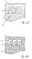
- FIG. 13 illustrating schematically a Polar Resistant Standard (PRS) test chamber according to the present invention for measuring 3D cellular confinement system pullout resistance.
- the PRS test chamber is especially adapted to test samples in predetermined three dimensional directions at, close or near to the surface where tightening is weak or normal stresses are low.
- the PRS test chamber comprises inter alia modules as defined below: a rigid container ( 1 ), characterized by stiffness and strength to withstand the hydraulic pressures during installation and testing, including inter alia at least two mobile walls.
- the container is characterized by main X, Y, and Z Cartesian axes, wherein X is length, Y is width and Z height (vertical axis); a clamping device ( 5 ).
- the tested cellular confinement system ( 3 ) applied normal to the horizontal at an angle ⁇ , wherein 17° ⁇ >162°, especially about 90°; a cable ( 6 ) interconnecting said clamping device ( 5 ) with a pulling mechanism ( 7 ); a load cell ( 8 ) connected to said cable ( 6 ) so as stress in cable is equal to stress on load cell; a predetermined measure of GRM ( 2 ) GRM in said rigid container ( 1 ), providing pressure against said system ( 3 ); and, optionally, a press ( 9 ), communicating with side facets of said pressed GRM ( 2 ), so that normal stresses can be controlled and adjusted to a pre-defined level in said GRM ( 2 ); embedding a CCS' cell strip or web within GRM ( 2 ); applying normal compressive stress uni-directionally through said GRM; pulling said CCS' cell, strip or web over it's entire embedded length along the at least one main Cartesian axis selected from Y, Z or any vector resolved form the parallelogram rule;
- the PRS test chamber hence assists in the design and testing of polar CCS, sheets or cells thereof having the ability to hinder and resist GRM movement, from more than one direction, preferably perpendicular, when the CCS or the tested CCS strip is embedded in GRM at, close to or near the surface.
- the PRS comprises further of sequentially pulling the said tested CCS' cell, strip or web over it's entire embedded length along said at least one main Cartesian axis selected from Y, Z or any vector resolved from the parallelogram rule. It is also in the scope of the present invention wherein said sequential order is selected from a group including inter alia said ‘Z’ and ‘Y’ Cartesian axes, thereby obtaining a vectorially resolved pullout resistance (N/cm) per said system cell, strip or web.
- Another object is to disclose a method for obtaining PRS as defined above, including inter alia further of embedding said CCS' cell, strip or web, at an angle of ⁇ to main axis X, ⁇ to main axis Y, and ⁇ to main axis Z, wherein 0° ⁇ , ⁇ , ⁇ >90°; pulling said CCS' cell, strip or web over it's entire length, along said angled plane; and, obtaining a pullout resistance (N/cm) per said tilted system cell, strip or web. It is also in the scope of the present invention wherein said system cell, strip or web is provided simultaneously. It is also in the scope of the present invention wherein the CCS' cell, strip or web is provided non-simultaneously.
- the CCS' cell, strip or web is embossed. It is still according to one embodiment of the invention that the system cell, strip, strip or web is apertured or perforated. It is also according to one embodiment of the invention that the CCS cell, strip or web is flapped.
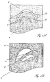
- FIG. 14A presenting a cross-sectional vertical view through two layers of GRM ( 141 ) and ( 142 ), separated by cellular confinement system ( 143 ) with non-protruding flap ( 144 ) in a location of equal normal stress across the system.
- GRMs 141 and 142 are compressed, tightened, or fastened to the same extent so as no normal stresses gradient across the system is obtained.
- FIG. 14B presenting a cross-sectional vertical view through two layers of GRM ( 141 ) and ( 1421 ), separated by cellular confinement system ( 143 ) in a location where GRM of ( 1421 ) loosens moderately, and a hydrostatic pressure gradient develops across the system.
- the flap ( 144 ) is induced to protrude moderately, in the direction of the moderately lower hydrostatic pressure gradient of approximately 0.1 Atmosphere.
- GRM 141 is more compressed, tightened, or fastened than 1421 so that normal pressure gradient across the system is developed.
- FIG. 14C presenting a cross sectional vertical view through two layers of GRM ( 141 ) and ( 1422 ), separated by cellular confinement system ( 143 ) in a location where GRM of ( 1421 ) loosens greatly and a hydrostatic pressure gradient develops across the system.
- the flap ( 144 ) is induced to protrude fully, in the direction of the greatly lowered hydrostatic pressure gradient of 0.6 Atmosphere.
- GRM 141 is highly compressed, tightened, or fastened with respect to 1422 , so that high normal pressure gradient across the system is developed.
- flaps can be defined as being suitable for a range of pressure gradients as exemplified by Low Pressure Flaps, which extend into the substrate at pressures ⁇ 0.05 Atmosphere, Medium Pressure Flaps, which extend into the substrate at pressures ⁇ 0.1 Atmosphere, and High Pressure Flaps, which extend into the substrate at pressures ⁇ 0.5 Atmosphere. It is acknowledged in that respect that those measures can be varied to match various filed conditions.
- Marlex RT K306 MDPE manufactured by Chevron PhilipsTM having a density of 0.937 g/cm 3 , was extruded at 260° C. in a single screw extruder, through a flat die and chilled on texturized metal rolls to an embossed strip having thickness of 1.2 mm.
- the strip was cut to 20 cm wide strips that are used as reference and named REF and represent the un-perforated strips currently available in the market.
- REF-P represents the perforated strips currently available in the market.
- the three kinds of strips were loaded to a PRS pullout device, and embedded in two GRMs: (a) sand having density 1.665 gr/cm 3 ; and, (b) graded crushed stone having density 2.15 gr/cm 3 .
- the strip width was 20 cm and its embedded length was 50 cm.
- the normal stress was set to 0.15 and 0.05 Atmosphere, in order to simulate situation in shallow GRMs and uppermost layers of geotechnical system s.
- the pullout resistance (load causing pullout divided by strip width) and deformation in the embedded sector (the 50 cm length) under said load were measured.
- Tab. 1 describes the results of the three different strip types in sand under normal pressure of 0.15 Atmosphere.
- Tab. 2 describes the results of the three different strip types in graded crushed stone under normal pressure of 0.15 Atmosphere.
- Tab. 3 describes the results of the three different strip types in sand under normal pressure of 0.05 Atmosphere.
- Tab. 4 describes the results of the three different strip types in graded crushed stone under normal pressure of 0.05 Atmosphere.
Landscapes
- Engineering & Computer Science (AREA)
- Mining & Mineral Resources (AREA)
- Life Sciences & Earth Sciences (AREA)
- General Life Sciences & Earth Sciences (AREA)
- Paleontology (AREA)
- Civil Engineering (AREA)
- General Engineering & Computer Science (AREA)
- Structural Engineering (AREA)
- Pit Excavations, Shoring, Fill Or Stabilisation Of Slopes (AREA)
- Mobile Radio Communication Systems (AREA)
- Buildings Adapted To Withstand Abnormal External Influences (AREA)
- Paper (AREA)
- Braking Arrangements (AREA)
- Cartons (AREA)
- Laminated Bodies (AREA)
- Woven Fabrics (AREA)
- Professional, Industrial, Or Sporting Protective Garments (AREA)
Priority Applications (1)
| Application Number | Priority Date | Filing Date | Title |
|---|---|---|---|
| US11/575,251 US8092896B2 (en) | 2005-12-29 | 2006-12-26 | Cellular confinement system |
Applications Claiming Priority (3)
| Application Number | Priority Date | Filing Date | Title |
|---|---|---|---|
| US75430305P | 2005-12-29 | 2005-12-29 | |
| PCT/IL2006/001486 WO2007074448A2 (en) | 2005-12-29 | 2006-12-26 | Improved cellular confinement system |
| US11/575,251 US8092896B2 (en) | 2005-12-29 | 2006-12-26 | Cellular confinement system |
Publications (2)
| Publication Number | Publication Date |
|---|---|
| US20080248236A1 US20080248236A1 (en) | 2008-10-09 |
| US8092896B2 true US8092896B2 (en) | 2012-01-10 |
Family
ID=38218379
Family Applications (1)
| Application Number | Title | Priority Date | Filing Date |
|---|---|---|---|
| US11/575,251 Expired - Fee Related US8092896B2 (en) | 2005-12-29 | 2006-12-26 | Cellular confinement system |
Country Status (12)
| Country | Link |
|---|---|
| US (1) | US8092896B2 (pl) |
| EP (1) | EP1962697B1 (pl) |
| JP (1) | JP4681057B2 (pl) |
| CN (1) | CN101547837B (pl) |
| AR (1) | AR059954A1 (pl) |
| CA (1) | CA2640053C (pl) |
| EA (1) | EA200800498A1 (pl) |
| IL (1) | IL181260A (pl) |
| PA (1) | PA8709901A1 (pl) |
| PL (1) | PL1962697T3 (pl) |
| UY (1) | UY30074A1 (pl) |
| WO (1) | WO2007074448A2 (pl) |
Cited By (5)
| Publication number | Priority date | Publication date | Assignee | Title |
|---|---|---|---|---|
| US8459903B2 (en) * | 2008-11-10 | 2013-06-11 | Reynolds Presto Products Inc. | Connection device for fastening expanded cell confinement structures and methods for doing the same |
| USD994445S1 (en) | 2021-06-30 | 2023-08-08 | Reynolds Presto Products Inc. | Connector for expanded cell confinement web with curved handle |
| USD1000262S1 (en) | 2021-06-30 | 2023-10-03 | Reynolds Presto Products Inc. | Connector device for expanded cell confinement web |
| USD1000263S1 (en) | 2021-06-30 | 2023-10-03 | Reynolds Presto Products Inc. | Connector for expanded cell confinement web with polygon handle |
| US11885091B2 (en) | 2021-06-30 | 2024-01-30 | Reynolds Presto Products Inc. | Connection device for fastening expanded cell confinement structures and methods for doing the same |
Families Citing this family (5)
| Publication number | Priority date | Publication date | Assignee | Title |
|---|---|---|---|---|
| WO2009042860A1 (en) | 2007-09-27 | 2009-04-02 | Prs Mediterranean Ltd. | Earthquake resistant earth retention system using geocells |
| US8721221B2 (en) | 2011-02-16 | 2014-05-13 | Premark Packaging Llc | System for providing flood protection and method of implementing same |
| US20170000085A1 (en) | 2015-07-02 | 2017-01-05 | Peachtree Pet Llc | Apparatus for protecting surfaces from pet caused damage |
| US20240279879A1 (en) * | 2023-02-16 | 2024-08-22 | Reynolds Presto Products Inc. | Vented Cell Structure for Confinement and Interlock of Earth Materials |
| WO2026058018A1 (en) | 2024-09-16 | 2026-03-19 | Soletanche Freyssinet | Cellular confinement system |
Citations (9)
| Publication number | Priority date | Publication date | Assignee | Title |
|---|---|---|---|---|
| DE1915523A1 (de) | 1968-03-26 | 1969-10-09 | Brevetex S A | Vorrichtung fuer den Erdschutz |
| US4481242A (en) * | 1982-07-29 | 1984-11-06 | Du Pont Canada, Inc. | Aquatic weed barrier |
| US4644685A (en) * | 1980-12-29 | 1987-02-24 | Suncast Corporation | Edging strip |
| US4798498A (en) | 1986-02-24 | 1989-01-17 | A/S Platon | Device for stabilizing bulk material |
| US4965097A (en) * | 1989-01-11 | 1990-10-23 | Reynolds Consumer Products, Inc. | Texturized cell material for confinement of concrete and earth materials |
| US5256007A (en) * | 1991-06-21 | 1993-10-26 | Robert Imhoff | Ground support system |
| WO2001048324A2 (en) | 1999-12-24 | 2001-07-05 | Alexandr Efimovich Merzlikin | Grid for localisation of materials |
| US6296924B1 (en) * | 1995-11-01 | 2001-10-02 | Reynolds Consumer Products, Inc. | System perforated cell confinement |
| US6554545B1 (en) * | 1998-06-01 | 2003-04-29 | Alethea Rosalind Melanie Hall | Framework and method of forming a support structure with interlocking of adjacent compartments |
Family Cites Families (7)
| Publication number | Priority date | Publication date | Assignee | Title |
|---|---|---|---|---|
| US4865097A (en) * | 1988-12-20 | 1989-09-12 | Allen Patricia L | Antique doll protection system |
| EP0378309A1 (en) * | 1989-01-11 | 1990-07-18 | Reynolds Consumer Products, Inc. | Vented cell material for confinement of concrete and earth materials |
| JP3582871B2 (ja) * | 1994-11-26 | 2004-10-27 | 武男 稲葉 | 構造物と盛土との境界部における道路構造 |
| JP3172701B2 (ja) * | 1997-12-15 | 2001-06-04 | 強化土エンジニヤリング株式会社 | 土工事用枠体および法枠工法 |
| CN2325422Y (zh) * | 1998-03-25 | 1999-06-23 | 北京燕化石油化工股份有限公司树脂应用研究所 | 塑料合页连接式土工格室组件 |
| EP1171668B1 (en) * | 1999-04-08 | 2005-08-31 | Beon Top Enterprises Ltd. | Retaining wall system with interlocked wall-building units |
| CN2400501Y (zh) * | 2000-01-17 | 2000-10-11 | 王滨生 | 蜂窝式网栅过滤装置 |
-
2006
- 2006-12-26 PL PL06821668T patent/PL1962697T3/pl unknown
- 2006-12-26 CN CN2006800535518A patent/CN101547837B/zh not_active Expired - Fee Related
- 2006-12-26 US US11/575,251 patent/US8092896B2/en not_active Expired - Fee Related
- 2006-12-26 WO PCT/IL2006/001486 patent/WO2007074448A2/en not_active Ceased
- 2006-12-26 JP JP2008548071A patent/JP4681057B2/ja not_active Expired - Fee Related
- 2006-12-26 EA EA200800498A patent/EA200800498A1/ru unknown
- 2006-12-26 EP EP06821668A patent/EP1962697B1/en active Active
- 2006-12-26 CA CA2640053A patent/CA2640053C/en not_active Expired - Fee Related
- 2006-12-28 PA PA20068709901A patent/PA8709901A1/es unknown
- 2006-12-28 UY UY30074A patent/UY30074A1/es unknown
- 2006-12-28 AR ARP060105867A patent/AR059954A1/es not_active Application Discontinuation
-
2007
- 2007-02-11 IL IL181260A patent/IL181260A/en not_active IP Right Cessation
Patent Citations (10)
| Publication number | Priority date | Publication date | Assignee | Title |
|---|---|---|---|---|
| DE1915523A1 (de) | 1968-03-26 | 1969-10-09 | Brevetex S A | Vorrichtung fuer den Erdschutz |
| US4644685A (en) * | 1980-12-29 | 1987-02-24 | Suncast Corporation | Edging strip |
| US4481242A (en) * | 1982-07-29 | 1984-11-06 | Du Pont Canada, Inc. | Aquatic weed barrier |
| US4798498A (en) | 1986-02-24 | 1989-01-17 | A/S Platon | Device for stabilizing bulk material |
| US4965097A (en) * | 1989-01-11 | 1990-10-23 | Reynolds Consumer Products, Inc. | Texturized cell material for confinement of concrete and earth materials |
| US5256007A (en) * | 1991-06-21 | 1993-10-26 | Robert Imhoff | Ground support system |
| US6296924B1 (en) * | 1995-11-01 | 2001-10-02 | Reynolds Consumer Products, Inc. | System perforated cell confinement |
| US6395372B1 (en) * | 1995-11-01 | 2002-05-28 | Reynolds Consumer Products, Inc. | Cell confinement structure |
| US6554545B1 (en) * | 1998-06-01 | 2003-04-29 | Alethea Rosalind Melanie Hall | Framework and method of forming a support structure with interlocking of adjacent compartments |
| WO2001048324A2 (en) | 1999-12-24 | 2001-07-05 | Alexandr Efimovich Merzlikin | Grid for localisation of materials |
Non-Patent Citations (1)
| Title |
|---|
| European Search Report dated Apr. 19, 2010. |
Cited By (7)
| Publication number | Priority date | Publication date | Assignee | Title |
|---|---|---|---|---|
| US8459903B2 (en) * | 2008-11-10 | 2013-06-11 | Reynolds Presto Products Inc. | Connection device for fastening expanded cell confinement structures and methods for doing the same |
| USD994445S1 (en) | 2021-06-30 | 2023-08-08 | Reynolds Presto Products Inc. | Connector for expanded cell confinement web with curved handle |
| USD1000262S1 (en) | 2021-06-30 | 2023-10-03 | Reynolds Presto Products Inc. | Connector device for expanded cell confinement web |
| USD1000263S1 (en) | 2021-06-30 | 2023-10-03 | Reynolds Presto Products Inc. | Connector for expanded cell confinement web with polygon handle |
| US11885091B2 (en) | 2021-06-30 | 2024-01-30 | Reynolds Presto Products Inc. | Connection device for fastening expanded cell confinement structures and methods for doing the same |
| USD1039957S1 (en) | 2021-06-30 | 2024-08-27 | Reynolds Presto Products Inc. | Connector device for expanded cell confinement web |
| US12320088B2 (en) | 2021-06-30 | 2025-06-03 | Reynolds Presto Products Inc. | Connection device for fastening expanded cell confinement structures and methods for doing the same |
Also Published As
| Publication number | Publication date |
|---|---|
| EP1962697A4 (en) | 2010-04-28 |
| CN101547837B (zh) | 2011-08-17 |
| CN101547837A (zh) | 2009-09-30 |
| PL1962697T3 (pl) | 2012-11-30 |
| UY30074A1 (es) | 2007-05-31 |
| JP2009526926A (ja) | 2009-07-23 |
| US20080248236A1 (en) | 2008-10-09 |
| CA2640053A1 (en) | 2007-07-05 |
| JP4681057B2 (ja) | 2011-05-11 |
| PA8709901A1 (es) | 2008-11-19 |
| WO2007074448A2 (en) | 2007-07-05 |
| EA200800498A1 (ru) | 2009-06-30 |
| EP1962697A2 (en) | 2008-09-03 |
| IL181260A (en) | 2009-05-04 |
| WO2007074448A3 (en) | 2009-03-26 |
| AR059954A1 (es) | 2008-05-14 |
| CA2640053C (en) | 2012-01-03 |
| EP1962697B1 (en) | 2012-06-27 |
Similar Documents
| Publication | Publication Date | Title |
|---|---|---|
| IL181260A (en) | Cellular confinement system | |
| Sireesh et al. | Bearing capacity of circular footing on geocell–sand mattress overlying clay bed with void | |
| Dash et al. | Bearing capacity of strip footings supported on geocell-reinforced sand | |
| Wang et al. | Effect of underground void on foundation stability | |
| Huckert et al. | Load transfer mechanisms in geotextile-reinforced embankments overlying voids: experimental and analytical approaches | |
| US8303218B2 (en) | Earthquake resistant earth retention system using geocells | |
| Tafreshi et al. | A comparison of static and cyclic loading responses of foundations on geocell-reinforced sand | |
| El Sawwaf et al. | The effect of soil reinforcement on pullout resistance of an existing vertical anchor plate in sand | |
| Choudhary et al. | Uplift capacity of horizontal anchor plate in geocell reinforced sand | |
| Chen et al. | Experimental and analytical studies of reinforced crushed limestone | |
| Mukherjee et al. | Pullout resistance of inclined anchors embedded in geogrid reinforced sand | |
| WO2009082077A1 (en) | Cellular reinforcement for soil particle confinement | |
| JP2024507588A (ja) | 向上した地盤工学インタラクションを有する力学的安定化水平ジオグリッド | |
| Bergado et al. | Localized mobilization of reinforcement force and its direction at the vicinity of failure surface | |
| Górniak et al. | Coupled discrete and finite-element modelling of geosynthetic tubes filled with granular material | |
| El Sawwaf | Uplift behavior of horizontal anchor plates buried in geosynthetic reinforced slopes | |
| US20240392527A1 (en) | Spider-web inspired geogrids | |
| Choudhary et al. | Failure mechanism of geocell-reinforced vertical plate anchors subjected to lateral loading | |
| Niroumand et al. | Uplift capacity of enlarged base piles in sand | |
| Al Salami et al. | Performance improvement of vertical anchor plates in sandy soil by using geogrid reinforcement | |
| US20240279879A1 (en) | Vented Cell Structure for Confinement and Interlock of Earth Materials | |
| JP2000192464A (ja) | 擁壁構造 | |
| Yazdandoust et al. | The use of the horizontal slice method to determine the pseudostatic coefficient in two-tiered geogrid and metal strip–reinforced soil walls | |
| Ehrlich | Performance of a 25m high anchored wall for stabilization of an excavation in gneiss saprolite | |
| Hausmann | Behaviour and analysis of reinforced soil |
Legal Events
| Date | Code | Title | Description |
|---|---|---|---|
| AS | Assignment |
Owner name: P.R.S. MEDITERRANEAN LTD., ISRAEL Free format text: ASSIGNMENT OF ASSIGNORS INTEREST;ASSIGNORS:EREZ, ODED;EREZ, ADI;REEL/FRAME:019010/0051 Effective date: 20070211 |
|
| STCF | Information on status: patent grant |
Free format text: PATENTED CASE |
|
| REMI | Maintenance fee reminder mailed | ||
| FPAY | Fee payment |
Year of fee payment: 4 |
|
| SULP | Surcharge for late payment | ||
| AS | Assignment |
Owner name: GEOTECH TECHNOLOGIES LTD., ISRAEL Free format text: ASSIGNMENT OF ASSIGNORS INTEREST;ASSIGNOR:PRS MEDITERRANEAN LTD.;REEL/FRAME:037658/0728 Effective date: 20150320 |
|
| FEPP | Fee payment procedure |
Free format text: MAINTENANCE FEE REMINDER MAILED (ORIGINAL EVENT CODE: REM.); ENTITY STATUS OF PATENT OWNER: LARGE ENTITY |
|
| LAPS | Lapse for failure to pay maintenance fees |
Free format text: PATENT EXPIRED FOR FAILURE TO PAY MAINTENANCE FEES (ORIGINAL EVENT CODE: EXP.); ENTITY STATUS OF PATENT OWNER: LARGE ENTITY |
|
| STCH | Information on status: patent discontinuation |
Free format text: PATENT EXPIRED DUE TO NONPAYMENT OF MAINTENANCE FEES UNDER 37 CFR 1.362 |
|
| FP | Lapsed due to failure to pay maintenance fee |
Effective date: 20200110 |