US8093902B2 - Device estimating a state of a secondary battery - Google Patents
Device estimating a state of a secondary battery Download PDFInfo
- Publication number
- US8093902B2 US8093902B2 US12/447,715 US44771508A US8093902B2 US 8093902 B2 US8093902 B2 US 8093902B2 US 44771508 A US44771508 A US 44771508A US 8093902 B2 US8093902 B2 US 8093902B2
- Authority
- US
- United States
- Prior art keywords
- current
- state
- battery
- secondary battery
- charge
- Prior art date
- Legal status (The legal status is an assumption and is not a legal conclusion. Google has not performed a legal analysis and makes no representation as to the accuracy of the status listed.)
- Active, expires
Links
- 230000014509 gene expression Effects 0.000 claims abstract description 276
- 239000011149 active material Substances 0.000 claims abstract description 122
- 238000009792 diffusion process Methods 0.000 claims abstract description 80
- 238000003487 electrochemical reaction Methods 0.000 claims abstract description 67
- 238000009826 distribution Methods 0.000 claims abstract description 16
- 239000000463 material Substances 0.000 claims description 37
- 239000008151 electrolyte solution Substances 0.000 claims description 33
- 238000006243 chemical reaction Methods 0.000 claims description 31
- 239000003990 capacitor Substances 0.000 claims description 29
- 239000000376 reactant Substances 0.000 claims description 29
- 238000009825 accumulation Methods 0.000 claims description 11
- 239000010416 ion conductor Substances 0.000 claims description 3
- 229910052744 lithium Inorganic materials 0.000 abstract description 55
- WHXSMMKQMYFTQS-UHFFFAOYSA-N Lithium Chemical compound [Li] WHXSMMKQMYFTQS-UHFFFAOYSA-N 0.000 abstract description 53
- 229910001416 lithium ion Inorganic materials 0.000 description 24
- HBBGRARXTFLTSG-UHFFFAOYSA-N Lithium ion Chemical compound [Li+] HBBGRARXTFLTSG-UHFFFAOYSA-N 0.000 description 15
- 238000010586 diagram Methods 0.000 description 15
- 230000001186 cumulative effect Effects 0.000 description 12
- 238000007599 discharging Methods 0.000 description 12
- 230000006870 function Effects 0.000 description 12
- 238000000034 method Methods 0.000 description 11
- 230000010287 polarization Effects 0.000 description 7
- 238000003411 electrode reaction Methods 0.000 description 5
- 230000007423 decrease Effects 0.000 description 4
- 230000001419 dependent effect Effects 0.000 description 4
- 230000008569 process Effects 0.000 description 4
- 230000003247 decreasing effect Effects 0.000 description 3
- 238000002474 experimental method Methods 0.000 description 3
- PXHVJJICTQNCMI-UHFFFAOYSA-N Nickel Chemical compound [Ni] PXHVJJICTQNCMI-UHFFFAOYSA-N 0.000 description 2
- 230000006399 behavior Effects 0.000 description 2
- 238000012790 confirmation Methods 0.000 description 2
- 230000000694 effects Effects 0.000 description 2
- 230000001771 impaired effect Effects 0.000 description 2
- 150000002641 lithium Chemical group 0.000 description 2
- 238000012986 modification Methods 0.000 description 2
- 230000004048 modification Effects 0.000 description 2
- 238000012545 processing Methods 0.000 description 2
- RYGMFSIKBFXOCR-UHFFFAOYSA-N Copper Chemical compound [Cu] RYGMFSIKBFXOCR-UHFFFAOYSA-N 0.000 description 1
- UFHFLCQGNIYNRP-UHFFFAOYSA-N Hydrogen Chemical compound [H][H] UFHFLCQGNIYNRP-UHFFFAOYSA-N 0.000 description 1
- 230000003044 adaptive effect Effects 0.000 description 1
- XAGFODPZIPBFFR-UHFFFAOYSA-N aluminium Chemical compound [Al] XAGFODPZIPBFFR-UHFFFAOYSA-N 0.000 description 1
- 229910052782 aluminium Inorganic materials 0.000 description 1
- 230000008901 benefit Effects 0.000 description 1
- 239000002131 composite material Substances 0.000 description 1
- 229910052802 copper Inorganic materials 0.000 description 1
- 239000010949 copper Substances 0.000 description 1
- 229910052739 hydrogen Inorganic materials 0.000 description 1
- 239000001257 hydrogen Substances 0.000 description 1
- 238000002847 impedance measurement Methods 0.000 description 1
- 229910052759 nickel Inorganic materials 0.000 description 1
- 230000003252 repetitive effect Effects 0.000 description 1
- 239000011347 resin Substances 0.000 description 1
- 229920005989 resin Polymers 0.000 description 1
- 230000004044 response Effects 0.000 description 1
- 230000001131 transforming effect Effects 0.000 description 1
Images





Classifications
-
- H—ELECTRICITY
- H01—ELECTRIC ELEMENTS
- H01M—PROCESSES OR MEANS, e.g. BATTERIES, FOR THE DIRECT CONVERSION OF CHEMICAL ENERGY INTO ELECTRICAL ENERGY
- H01M10/00—Secondary cells; Manufacture thereof
- H01M10/42—Methods or arrangements for servicing or maintenance of secondary cells or secondary half-cells
- H01M10/48—Accumulators combined with arrangements for measuring, testing or indicating the condition of cells, e.g. the level or density of the electrolyte
-
- G—PHYSICS
- G01—MEASURING; TESTING
- G01R—MEASURING ELECTRIC VARIABLES; MEASURING MAGNETIC VARIABLES
- G01R31/00—Arrangements for testing electric properties; Arrangements for locating electric faults; Arrangements for electrical testing characterised by what is being tested not provided for elsewhere
- G01R31/36—Arrangements for testing, measuring or monitoring the electrical condition of accumulators or electric batteries, e.g. capacity or state of charge [SoC]
- G01R31/367—Software therefor, e.g. for battery testing using modelling or look-up tables
-
- G—PHYSICS
- G01—MEASURING; TESTING
- G01R—MEASURING ELECTRIC VARIABLES; MEASURING MAGNETIC VARIABLES
- G01R31/00—Arrangements for testing electric properties; Arrangements for locating electric faults; Arrangements for electrical testing characterised by what is being tested not provided for elsewhere
- G01R31/36—Arrangements for testing, measuring or monitoring the electrical condition of accumulators or electric batteries, e.g. capacity or state of charge [SoC]
- G01R31/382—Arrangements for monitoring battery or accumulator variables, e.g. SoC
- G01R31/3842—Arrangements for monitoring battery or accumulator variables, e.g. SoC combining voltage and current measurements
-
- H—ELECTRICITY
- H01—ELECTRIC ELEMENTS
- H01M—PROCESSES OR MEANS, e.g. BATTERIES, FOR THE DIRECT CONVERSION OF CHEMICAL ENERGY INTO ELECTRICAL ENERGY
- H01M10/00—Secondary cells; Manufacture thereof
- H01M10/42—Methods or arrangements for servicing or maintenance of secondary cells or secondary half-cells
- H01M10/44—Methods for charging or discharging
-
- Y—GENERAL TAGGING OF NEW TECHNOLOGICAL DEVELOPMENTS; GENERAL TAGGING OF CROSS-SECTIONAL TECHNOLOGIES SPANNING OVER SEVERAL SECTIONS OF THE IPC; TECHNICAL SUBJECTS COVERED BY FORMER USPC CROSS-REFERENCE ART COLLECTIONS [XRACs] AND DIGESTS
- Y02—TECHNOLOGIES OR APPLICATIONS FOR MITIGATION OR ADAPTATION AGAINST CLIMATE CHANGE
- Y02E—REDUCTION OF GREENHOUSE GAS [GHG] EMISSIONS, RELATED TO ENERGY GENERATION, TRANSMISSION OR DISTRIBUTION
- Y02E60/00—Enabling technologies; Technologies with a potential or indirect contribution to GHG emissions mitigation
- Y02E60/10—Energy storage using batteries
Definitions
- the present invention relates generally to devices estimating a state of a secondary battery and in particular to devices estimating a state of a secondary battery in accordance with a battery model allowing the secondary battery's internal state to be estimated based on an electrochemical reaction.
- a power supply system configured such that a chargeable secondary battery supplies a load with electric power and the secondary battery can also be charged as required while the load is in operation.
- hybrid vehicles, electric vehicles and the like including as a driving force source an electric motor driven by a secondary battery have such power supply systems mounted therein.
- the secondary battery's stored electric power is used as electric power driving the electric motor serving as the driving force source, and electric power generated when the electric motor regenerates electric power, electric power generated by an electric power generator as an engine rotates, and the like charge the secondary battery.
- SOC state of charge
- the secondary battery For hybrid vehicles in particular, it is necessary that the secondary battery have its state of charge controlled to be approximately intermediate between its fully charged state (100%) and its completely uncharged state (0%), i.e., 50 to 60%, so that the secondary battery can receive regenerated electric power and also supply the electric motor with electric power immediately as required.
- over-discharging or overcharging a secondary battery may degrade the battery's performance and reduce its life.
- an intermediate SOC is set as a target for control, as described above, and a secondary battery is accordingly charged/discharged repeatedly in its use
- the secondary battery's amount of charge is monitored sequentially and charging/discharging the secondary battery is controlled to restrict overcharging/over-discharging the secondary battery.
- patent document 1 Japanese Patent Laying-open No. 2005-37230 discloses a technique to estimate from a value of a cumulative current of a battery how the battery varies in SOC.
- patent document 1 describes that a current sensor measures the battery's current and in parallel therewith an operation is performed to obtain an estimated charged/discharged current, and an operation is performed to obtain the battery's current to obtain a measured SOC, while the estimated charged/discharged current is accumulated to obtain an estimated SOC.
- a difference between the estimated SOC and the measured SOC is obtained and how the difference in SOC varies with time is accumulated to obtain a cumulative SOC value, and when the cumulative SOC value is equal to or larger than a predetermined value in comparison with an initial value, that the battery is degraded is detected.
- patent document 2 Japanese Patent Laying-open No. 2004-178848 discloses a device estimating a state of charge of a secondary battery, that is configured such that an adaptive digital filter is used to estimate no load voltage (OCV) from a value of the secondary battery's current as measured and that of a terminal's voltage as measured and a state of charge is estimated in accordance with a previously obtained relationship between no load voltage and a state of charge.
- OCV no load voltage
- This device estimating a state of charge of a secondary battery employs a low pass filter as the secondary battery's internal equivalent circuit model, and it is thus difficult to precisely estimate the secondary battery's internal behavior involving the diffusion of a reaction involved material contributing to an electrochemical reaction.
- non-patent document 1 (W. B. Gu and C. Y. Wang, THERMAL-ELECTROCHEMICAL COUPLED MODELING OF A LITHIUM-ION CELL, ECS Proceedings Vol. 99-25 (1), 2000, ECS, pp. 748-762) discusses a battery model employing an expression of an electrochemical reaction internal to a lithium battery and reports that a characteristic can be represented with high precision in comparison with an actual battery.
- non-patent document 1 indicates that the secondary battery's no load voltage depends on a local SOC obtained at an electrode's interface with an electrolytic solution (a surface of an active material) and as a result the battery's voltage in relaxation is governed by diffusion of lithium depending on how lithium is distributed in concentration in an active material.
- the document discloses that the diffusion of the reaction involved material (lithium) in the active material is governed by a diffusion equation of spherical coordinates handling the active material as a sphere and a diffusion rate of a material governed by a diffusion coefficient in a diffusion process.
- the secondary battery's internal state will estimated by a macro equivalent model with the secondary battery's voltage and current serving as an input and an output, and it is difficult to provide estimation with high precision based on the secondary battery's internal state involving the reaction involved material's diffusion.
- non-patent document 1 if the reaction involved material's diffusion is represented by a diffusion equation, as based on the battery's internal electrochemical reaction, and the battery's open circuit voltage depends on a local SOC obtained at an electrode-electrolytic solution interface (a surface of an active material), then while the battery model will be non-linear, the battery's state can be estimated with higher precision.
- an analysis provided in accordance with the model disclosed in non-patent document 1 involves a significantly large operating load and it is thus difficult for example to mount it in an actual device and estimate a state on line when the secondary battery is used.
- the present invention has been made to overcome such disadvantage as described above, and it contemplates a device estimating a state of a secondary battery, that employs a battery model allowing the battery's internal state to be estimated from an electrochemical reaction and also achieving an alleviated operating load, and is thus suitable for being mounted in an actual device.
- the present device estimating a state of a secondary battery is a device estimating a state of a secondary battery including first and second electrodes configured to include an active material containing a reactant material contributing to an electrochemical reaction and an ion conductor for conducting between the first and second electrodes the reactant material ionized.
- the device comprises a voltage detector, a diffusion estimation unit, an open circuit voltage estimation unit, a current estimation unit, and a boundary condition setting unit.
- the voltage detector detects a voltage of the battery between the first and second electrodes.
- the diffusion estimation unit estimates a distribution in concentration of the reactant material in accordance with an active material diffusion model expression defining the distribution in concentration of the reactant material in the active material, as based on a given boundary condition.
- the open circuit voltage estimation unit estimates an open circuit voltage between the first and second electrodes, as based on a concentration of the reactant material obtained at an interface of the active material with an electrolytic solution, as estimated by the diffusion estimation unit.
- the current estimation unit estimates a density of a current of the secondary battery in accordance with a voltage-current relationship model expression based on the electrochemical reaction and indicating a relationship between the open circuit voltage, an overvoltage calculated in accordance with the density of the current of the secondary battery, a voltage drop caused in accordance with the density of the current of the secondary battery, and the voltage of the battery.
- the current estimation unit calculates the density of the current of the secondary battery by substituting in the voltage-current relationship model expression the voltage of the battery detected by the voltage detector, the open circuit voltage estimated by the open circuit voltage estimation unit, and a parameter value of the secondary battery.
- the boundary condition setting unit calculates a reaction current density at the interface, as based on the density of the current of the battery estimated by the current estimation unit, and sets the boundary condition for the diffusion estimation model expression for the interface in accordance with the reaction current density calculated.
- the above device estimating a state of a secondary battery can estimate how a reactant material (representatively, lithium in a lithium battery) is diffused in an active material in accordance with an active material diffusion model expression and combine the active material diffusion model expression with a simplified a voltage-current relationship model expression estimating the secondary battery's current density from an open circuit voltage (OCV, which is synonymous with no load voltage) estimated from a concentration of the reactant material estimated at an interface of the active material with the electrolytic solution, the battery's voltage as measured, and a parameter value previously obtained for the secondary battery to estimate how the reactant material is distributed in concentration.
- OCV open circuit voltage
- a battery model expression can thus be implemented that allows a simplified a voltage-current relationship model expression to alleviate an operating load and a secondary battery's internal state to be estimated from an electrochemical reaction with high precision.
- the device estimating a state of a secondary battery further comprises a temperature detector, and a parameter value setting unit for setting the parameter value variably in accordance with at least the temperature of the battery.
- the temperature detector detects the temperature of the secondary battery.
- the parameter value setting unit further sets a parameter value indicative of a diffusion rate in the active material diffusion model expression variably in accordance with at least the temperature of the battery.
- a parameter value used in a battery model expression can be set variably in accordance with the secondary battery's temperature.
- a battery parameter's temperature dependence can thus be reflected to further precisely estimate the secondary battery's state.
- the voltage-current relationship model expression is configured by a linearly approximated expression indicating that the open circuit voltage minus a product of the density of the current of the battery and an electrical resistance provided per a unit area of the electrode that is served as the parameter value is a voltage equal to the voltage of the battery, and the parameter value setting unit sets the electrical resistance variably in accordance with the concentration of the reactant material obtained at the interface, as estimated by the diffusion estimation unit, and the temperature of the battery detected by the temperature detector.
- the linearly approximated expression can eliminate the necessity of performing a convergent calculation in an operation of a voltage-current relationship model expression estimating a battery's current density from the battery's voltage. This can alleviate a load of and stabilize the operation by the voltage-current relationship model expression, and a battery model expression can be implemented that is suitable for being mounted in an actual device.
- the device estimating a state of a secondary battery further comprises a current operation unit that separates the density of the current of the secondary battery in total into a first current density contributing to the electrochemical reaction and a second current density caused by a component caused in the secondary battery for an electric double layer capacitor.
- the boundary condition setting unit calculates the reaction current density at the interface, as based on the first current density calculated by the current operation unit, and in the voltage-current relationship model expression the overvoltage is calculated based on the first current density.
- the secondary battery's entire current component can have separated therefrom a current that flows through an electric double layer capacitor and thus does not contribute to an electrochemical reaction, and the active material diffusion model expression and the voltage-current relationship model expression can thus be operated. Estimation with improved precision can be achieved.
- the device estimating a state of a secondary battery further comprises: a temperature detector that detects a temperature of the secondary battery; and a parameter value setting unit for setting the parameter value variably in accordance with at least the temperature of the battery.
- the voltage-current relationship model expression is configured of: a linearly approximated expression indicating that a product of the first current density and a first electrical resistance provided per a unit area of the electrode that is served as the parameter value is equal to the voltage of the battery; and an expression indicating that the second current density that is served as the parameter value and flowing through the capacitor per the unit area of the electrode is a value proportional to an amount of the voltage of the battery that varies with time.
- the parameter value setting unit sets the first electrical resistance variably in accordance with the concentration of the reactant material obtained at the interface, as estimated by the diffusion estimation unit, and the temperature of the battery detected by the temperature detector, and also variably sets a capacitance per the unit area of the electrode in accordance with the temperature of the battery.
- the linearly approximated expression can eliminate the necessity of performing a convergent calculation in an operation of a voltage-current relationship model expression estimating a battery's current density from the battery's voltage. This can alleviate a load of and stabilize the operation by the voltage-current relationship model expression, and a battery model expression can be implemented that is suitable for being mounted in an actual device.
- the diffusion estimation unit has the active material diffusion model expression represented by a polar coordinate for each of the first and second electrodes.
- first and second electrodes separate active material diffusion models can be created, respectively, and for each electrode how a reactant material (e.g., lithium) diffuses can be modeled. Estimation can be done with improved precision.
- a reactant material e.g., lithium
- the diffusion estimation unit has the active material diffusion model expression represented by a polar coordinate and shared by the first and second electrodes.
- first and second electrodes can share a single active material diffusion model.
- a battery model expression can be implemented that contemplates a further alleviated operating load and is thus further suitable for being mounted in an actual device.
- the voltage-current relationship model expression is derived as based on: a voltage equation indicating a relationship between average potentials of the active material and the electrolytic solution, an average value of an overvoltage generated as the electrochemical reaction is caused at the interface, and the open circuit voltage; and an electrochemical reaction expression indicating a relationship between the density of the current of the battery and the average value of the overvoltage.
- the voltage-current relationship model expression is derived by simplifying a distribution in potential of the active material in the electrode and the electrolytic solution to a quadric, and in that condition, obtaining the average potentials of the active material and the electrolytic solution.
- the voltage-current relationship model expression is derived as based on: a voltage equation indicating a relationship between average potentials of the active material and the electrolytic solution, an overvoltage generated as the electrochemical reaction is caused, and the open circuit voltage, and furthermore, an electrochemical reaction expression indicating a relationship between the density of the current of the battery and the average value of the overvoltage.
- the device estimating a state of a secondary battery further comprises an average concentration calculation unit and a first state-of-charge estimation unit.
- the average concentration calculation unit calculates an average concentration of the reactant material in the active material, as based on the distribution in concentration of the reactant material estimated by the diffusion estimation unit.
- the first state-of-charge estimation unit estimates a state of charge of the secondary battery in accordance with a previously obtained correspondence relationship between the average concentration and the state of charge, as based on the average concentration calculated by the average concentration calculation unit.
- the secondary battery's state of charge can be estimated in accordance with an average concentration of the reactant material in the active material of the electrode.
- the state of charge can be estimated with high precision based on a state estimated from an electrochemical reaction caused in the secondary battery.
- the device estimating a state of a secondary battery further comprises a current detector, a second state-of-charge estimation unit, and a third state-of-charge estimation unit.
- the current detector detects a current of the secondary battery.
- the second state-of-charge estimation unit estimates an amount of variation of the state of charge of the secondary battery, as based on the current of the battery accumulated.
- the third state-of-charge estimation unit sequentially updates an estimated value of the state of charge of the secondary battery, as based on a result of estimating by the first and second state-of-charge estimation units.
- the third state-of-charge estimation unit calculates a current value of the estimated value of the state of charge by reflecting the amount of variation of the state of charge from the previous value estimated by the second state-of-charge estimation unit, and an error in state of charge between a current state of charge estimated by the first state-of-charge estimation unit and the previous value, in a previous value of the estimated value of the state of charge, on the previous value.
- the amount of variation of the state of charge is reflected with a time constant relatively smaller than that applied in reflecting the error in state of charge.
- estimating a state of charge based on a cumulative measured current value which is highly precise for short-term estimation, and estimating a state of charge based on the above described battery model, can be combined together to estimate the secondary battery's state of charge with high precision.
- the device estimating a state of a secondary battery further comprises a current detector, a second state-of-charge estimation unit, and a third state-of-charge estimation unit.
- the current detector detects a current of the secondary battery.
- the second state-of-charge estimation unit estimates an amount of variation of the state of charge of the secondary battery, as based on the current of the battery accumulated.
- the third state-of-charge estimation unit sequentially updates an estimated value of the state of charge of the secondary battery, as based on a result of estimating by the first and second state-of-charge estimation units.
- the third state-of-charge estimation unit calculates a current value of the estimated value of the state of charge by reflecting the amount of variation of the state of charge from the previous value estimated by the second state-of-charge estimation unit, and an error in state of charge between a current state of charge estimated by the first state-of-charge estimation unit and a previous value of the estimated value of the state of charge, on the previous value.
- the third state-of-charge estimation unit ceases to reflect the error in state of charge and calculates the current value of the estimated value of the state of charge.
- the battery model's estimation error can be prevented from contributing to a state of charge estimated with poor precision.
- the device estimating a state of a secondary battery further comprises an offset estimation unit that calculates an estimated value of the current of the battery, as based on the density of the current of the battery estimated by the current estimation unit, and estimates an offset error of the current detector, as based on an error of the estimated value of the current of the battery and a value detected by the current detector.
- the second state-of-charge estimation unit uses the offset error estimated by the offset estimation unit to correct the value of the current of the battery detected by the current detector, and estimates the amount of variation of the state of charge of the secondary battery, as based on an accumulation of the value detected that is corrected.
- the device estimating a state of a secondary battery further comprises a current detector, an offset estimation unit, and a state-of-charge estimation unit.
- the current detector detects a current of the secondary battery.
- the offset estimation unit calculates an estimated value of the current of the battery, as based on the density of the current of the battery estimated by the current estimation unit, and estimates an offset error of the current detector, as based on an error of the estimated value of the current of the battery and a value detected by the current detector.
- the state-of-charge estimation unit uses the offset error estimated by the offset estimation unit to correct the value of the current of the battery detected by the current detector, and estimates an amount of variation of the state of charge of the secondary battery, as based on an accumulation of the value detected that is corrected.
- the current detector's offset can be estimated from the battery's current estimated through a battery model and a measured current value with the offset corrected can be accumulated to allow a state of charge to be estimated from a cumulative current with improved precision.
- a major advantage of the present invention lies in being capable of implementing a device estimating a state of a secondary battery that employs a battery model that allows the secondary battery's internal state to be estimated from an electrochemical reaction and also achieves an alleviated operating load, and is thus suitable for being mounted in an actual device.
- FIG. 1 is a block diagram schematically illustrating an exemplary configuration of a power supply system having applied thereto a device estimating a state of a secondary battery according to an embodiment of the present invention.
- FIG. 2 schematically shows a configuration of a secondary battery.
- FIG. 3 is a list of variables and constants employed in a battery model expression.
- FIG. 4 conceptually illustrates an outline of modeling a secondary battery in the present embodiment.
- FIG. 5 conceptually illustrates a model of an active material represented by a polar coordinate.
- FIG. 6 conceptually illustrates a relationship of a voltage of a terminal of a secondary battery and each average potential.
- FIG. 7 conceptually illustrates a dependence of a diffusion coefficient on temperature.
- FIG. 8A and FIG. 8B conceptually show a relationship between open circuit voltage and local SOC.
- FIG. 9 is a block diagram schematically illustrating a configuration of a device estimating a state of a secondary battery according to a first embodiment.
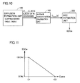
- FIG. 10 is a block diagram illustrating an SOC estimation configuration of the device estimating a state of a secondary battery according to the first embodiment.
- FIG. 11 shows a relationship between an average lithium concentration in an active material and a state of charge (SOC).
- FIG. 12 is a flowchart for illustrating how the device estimating a state of a secondary battery according to the first embodiment estimates the battery's state and SOC through a process having a series of steps.
- FIG. 13 conceptually illustrates self modification of an SOC estimation error by the device estimating a state of a secondary battery according to the first embodiment.
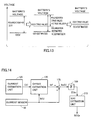
- FIG. 14 is a block diagram for illustrating how a device estimating a state of a secondary battery estimates an SOC according to a second embodiment.
- FIG. 15 is a conceptual waveform diagram representing a relationship between a value of a current of a battery as measured by a sensor and a model estimated value thereof.
- FIG. 16 is a conceptual waveform diagram representing an offset error of a current sensor.
- FIG. 17 is a flowchart for implementing estimating an SOC according to the second embodiment, as shown in FIG. 14 , by a battery ECU.
- FIG. 18 is a block diagram for illustrating how a device estimating a state of a secondary battery estimates an SOC according to the second embodiment in an exemplary variation.
- FIG. 19 is a flowchart for implementing estimating an SOC according to the exemplary variation of the second embodiment, as shown in FIG. 18 , by a battery ECU.
- FIG. 20 is a circuit diagram schematically showing a secondary battery's equivalent circuit model with an electric double layer capacitor considered.
- FIG. 21 is a block diagram for schematically illustrating a configuration of a device estimating a state of a secondary battery according to a third embodiment.
- FIG. 1 is a block diagram schematically illustrating an exemplary configuration of a power supply system having applied thereto a device estimating a state of a secondary battery according to an embodiment of the present invention.
- a power supply system 5 is configured of a secondary battery 10 , a load 20 , and a battery ECU 50 and a control device 60 configured of an electronic control unit (ECU).
- ECU electronice control unit
- Each ECU is representatively configured of a microcomputer and a memory (random access memory (RAM), read only memory (ROM), or the like) for performing a previously programmed predetermined sequence and predetermined operation.
- RAM random access memory
- ROM read only memory
- Chargeable and dischargeable secondary battery 10 is representatively implemented as a lithium ion battery, which is suitable for application to the present invention as the battery has an output characteristic varying with how a reactant material (lithium) is distributed in the battery, in an active material of an electrode in particular, in concentration.
- a reactant material lithium
- Secondary battery 10 is provided with a temperature sensor 30 measuring the battery's temperature Tb, a current sensor 32 measuring a current Ib input/output to/from secondary battery 10 (hereinafter also referred to as “the battery's current Ib”), and a voltage sensor 34 measuring an inter-terminal voltage Vb between a positive electrode and a negative electrode (hereinafter also referred to as “the battery's voltage Vb”).
- Load 20 is driven by electric power output from secondary battery 10 . Furthermore, it is assumed that an electric power generating/feeding element (not shown) is provided to be included in load 20 or separately from load 20 and that secondary battery 10 is chargeable with a current charged from the electric power generating/feeding element. Accordingly, when secondary battery 10 is discharged, the battery's current is positive (i.e., >0), and when secondary battery 10 is charged, the battery's current is negative (i.e., ⁇ 0).
- Battery ECU 50 receives values detected by the group of sensors 30 , 32 , 34 provided for secondary battery 10 and, based thereon, follows a battery model allowing an internal state of secondary battery 10 to be estimated from an electrochemical reaction, as will be described hereinafter more specifically, to calculate an estimated state value indicative of the battery's state sequentially for each predetermined period.
- battery ECU 50 Furthermore, from the estimated state value calculated, battery ECU 50 generates battery information for restricting charging/discharging the secondary battery.
- the battery information includes an SOC (0% to 100%) indicating an charged amount (or available capacitance) relative to a fully charged state (100%), an electric power allowed to be input Win indicating an upper limit value for electric power currently permitted to be charged and an electric power allowed to be output Wout indicating an upper limit value for electric power discharged, and the like.
- Control device 60 operates in response to a request to load 20 for operation and with the battery information received from battery ECU 50 taken into consideration to limit charging/discharging secondary battery 10 to avoid overcharging or over-discharging secondary battery 10 , and in that condition generates an instruction to operate load 20 .
- control device 60 limits the electric power that is input/output to/from secondary battery 10 to be the electric power allowed to be input Win/the electric power allowed to be output Wout and generates the instruction to operate load 20 .
- secondary battery 10 has an SOC of at most a lower limit value
- control device 60 prohibits load 20 from performing an operation consuming electric power or compulsorily initiates an operation of load 20 to generate electric power (or an operation to charge secondary battery 10 ).
- control device 60 compulsorily prohibits load 20 from performing the operation generating electric power.
- FIG. 2 schematically shows a configuration of the secondary battery.
- secondary battery 10 includes a negative electrode 12 , a separator 14 , and a positive electrode 15 .
- Separator 14 is configured of resin provided between negative electrode 12 and positive electrode 15 and having an electrolytic solution permeated therein. Separator 14 corresponds to an “ion conductor” in the present invention. Furthermore, a horizontal axial coordinate x indicates a position in the electrodes' depthwise direction.
- Negative electrode 12 and positive electrode 15 are each configured of an aggregate of a spherical active material 18 .
- a chemical reaction is caused on an interface of active material 18 of negative electrode 12 to discharge lithium ion Li + and electron e ⁇ while on an interface of active material 18 of positive electrode 15 a chemical reaction is caused to absorb lithium ion Li + and electron e ⁇ .
- Negative electrode 12 is provided with a current collector 13 absorbing electron e ⁇ and positive electrode 15 is provided with a current collector 16 discharging electron e ⁇ .
- the negative electrode's current collector 13 is configured of copper and the positive electrode's current collector 16 is configured of aluminum.
- Current collector 13 is provided with a terminal 11 n of the negative electrode and current collector 16 is provided with a terminal 11 p of the positive electrode.
- a secondary battery charging device employs a basic battery model expression indicated by primitive equations of expressions (1) to (11) indicated below. Furthermore, FIG. 3 is a list of variables and constants used in the battery model expression.
- a representation of (t) indicating a function of time, a representation of (T) indicating dependence on the battery's temperature, and a representation of ( ⁇ ) indicating dependence on a local SOC ⁇ , and the like may be omitted in the present specification.
- a symbol # added to a variable or a constant represents an average value.
- an expression (3) is established as an expression relating to a principle of conservation in density of lithium ions in the electrolytic solution.
- a diffusion equation of expression (4) and a boundary condition expression indicated by expressions (5) and (6) are applied as expressions relating to a principle of conservation in concentration of lithium in the active material.
- An expression (5) indicates a boundary condition at a center of the active material and an expression (6) indicates a boundary condition at an interface of the active material with the electrolytic solution (hereinafter also simply referred to as an “interface”).
- the active material's interface has a local lithium distribution in concentration, or a local SOC ⁇ j , defined by an expression (7).
- c sj,max represents a concentration of lithium at the interface of the active material of the positive and negative electrodes, as indicated in an expression (8).
- a lithium concentration limit in the active material represents a lithium concentration limit in the active material.
- an expression (9) is established as an expression relating to the principle of conservation of charge in the electrolytic solution and an expression (10) is established as an expression relating to the principle of conservation of charge in the active material.
- an expression (11) is established as an expression of an electrochemical reaction caused at the active material's interface, indicating a relationship between a current density I(t) and a reaction current density j j Li .
- the primitive equations of expressions (1) to (11) are those disclosed in non-patent document 1. Exactly applying these battery model expressions to a state estimation device mounted in an actual device and estimating a secondary battery's state on line is, however, extremely difficult due to a restriction on an ECU's (battery ECU 50 's) operating load and operating time. Accordingly in the present embodiment the battery model expression is simplified, as will be described hereinafter.
- negative electrode 12 and positive electrode 15 each have an electrochemical reaction uniformly. More specifically, it is assumed that each electrode 12 , 15 has the reaction uniformly in a direction x. Furthermore, as it is assumed that negative electrode 12 and positive electrode 15 each internally have each active material's reaction uniformly, a single active material model will be handled in each of negative electrode 12 and positive electrode 15 . Consequently, the FIG. 2 secondary battery's schematic structure is modeled as shown in FIG. 4 .
- an electrode reaction is caused at a surface of the negative electrode's active material model 18 n .
- Active material model 18 n thus has a lithium atom Li discharging an electron e ⁇ and thus becoming a lithium ion Li + and thus discharged to an electrolytic solution in separator 14 .
- an electrode reaction caused at a surface of the positive electrode's active material model 18 p allows the lithium ion Li + in the electrolytic solution to be taken in and the electron e ⁇ to be absorbed. The lithium atom Li is thus taken into the positive electrode's active material model 18 p .
- an electrode reaction caused at a surface of the negative electrode's active material model 18 n allows a lithium ion Li + in the electrolytic solution to be taken in and an electrode reaction caused at a surface of the positive electrode's active material model 18 p allows a lithium ion Li + to be discharged to the electrolytic solution.
- each active material model 18 p , 18 n has a lithium concentration c s , which can be represented as a function on a radial coordinate r (r: a distance from a center of each point, r s : a radius of the active material), assuming that it is position-independent as seen circumferentially.
- expression (9) which relates to the principle of conservation of charge in the electrolytic solution, is simplified to an expression (12), indicated below, by expression (3′) assuming that the electrodes have an electrochemical reaction therein uniformly and that the electrolytic solution is invariable in concentration with time. More specifically, the electrolytic solution has a potential ⁇ ej approximated by a quadric of x, and an average potential ⁇ ej # in the electrolytic solution used in calculating overvoltage ⁇ j # is obtained by integrating expression (12) with respect to the electrode's thickness L j , i.e., by an expression (13) indicated below.
- an expression (14) indicated below is established from expression (12), and accordingly, the electrolytic solution's average potential ⁇ e2 # and the electrolytic solution's potential at a boundary with separator 14 will have a difference in potential, as represented by an expression (15) indicated below. Similarly, for positive electrode 15 , the electrolytic solution's average potential ⁇ e1 # and the electrolytic solution's potential at a boundary with separator 14 will have a difference in potential, as represented by an expression (16) indicated below.
- expression (10) relating to the principle of conservation of charge in the active material is also simplified to an expression (17) indicated below. More specifically, the active material also has a potential j approximated by a quadric of x, and an average potential ⁇ sj # in the active material used in calculating overvoltage ⁇ j # is obtained by integrating expression (17) with respect to the electrode's thickness L j , i.e., by an expression (18) indicated below. Accordingly, similarly as described for the potential in the electrolytic solution, for positive electrode 15 , the active material's average potential ⁇ s1 # and the active material's potential at a boundary with an electric collector (current collector 16 ) have a difference in potential, as indicated below by an expression (19). For negative electrode 12 , an expression (20) is similarly established.
- an active material diffusion model expression (M2a) is obtained for active material models 18 p and 18 n at positive electrode 15 and negative electrode 12 , respectively.
- V ⁇ ( t ) U 1 ⁇ # ⁇ ( ⁇ 1 , t ) - U 2 ⁇ # ⁇ ( ⁇ 2 , t ) + RT ⁇ a ⁇ ⁇ 1 ⁇ F ⁇ ⁇ arcsin ⁇ ⁇ h ⁇ ( - I ⁇ ( t ) 2 ⁇ L 1 ⁇ a s ⁇ ⁇ 1 ⁇ i 01 ⁇ ( ⁇ 1 , T , t ) ) - arcsin ⁇ ⁇ h ⁇ ( - I ⁇ ( t ) 2 ⁇ L 2 ⁇ a s ⁇ ⁇ 2 ⁇ i 02 ⁇ ( ⁇ 2 , T , t ) ) ⁇ - I ⁇ ( t ) ⁇ ( L 1 3 ⁇ ⁇ 1 eff + L s 3 ⁇ ⁇ s eff + L 2 3 ⁇ ⁇ 2 eff + L 1 3 ⁇ ⁇ 1 eff + L 2 3 ⁇ ⁇ 2 eff +
- model expression (M1a) on the right-hand side the first term indicates an open circuit voltage (OCV) determined by a concentration of a reactant material (lithium) that is obtained at a surface of the active material and the second term indicates overvoltage ( ⁇ 1 #- ⁇ 2 #) and the third term indicates a voltage drop attributed to the battery's current. More specifically, the secondary battery's pure direct current resistance is represented in expression (M1a) by Rd(T).
- diffusion coefficients D s1 and D s2 used as a parameter value defining a diffusion rate of the reactant material, or lithium, are temperature-dependent. Accordingly, diffusion coefficients D s1 and D s2 are set, for example in accordance with a map shown in FIG. 7 , as a variable parameter value set variably relative to the battery's temperature T detected by temperature sensor 30 . As shown in FIG. 7 , diffusion coefficients D s1 and D s2 have a characteristic that relatively decreases when the battery has low temperature and that relatively increases as the battery's temperature increases.
- diffusion coefficients D s1 and D s2 may be dependent not only on temperature but also local SOC ⁇ , and in that case, a two dimensional map is previously prepared that sets these diffusion coefficients as a parameter value in accordance with the battery's temperature T as detected and a local SOC ⁇ as estimated.
- open circuit voltages U 1 and U 2 also have a dependence increasing or decreasing as local SOC ⁇ decreases, as shown in FIG. 8A and FIG. 8B . Accordingly, such local SOC dependence is reflected in previously setting a map setting open circuit voltages U 1 and U 2 in expression (M1a) in accordance with local SOC ⁇ as estimated.
- exchange current densities i 01 and i 02 also have dependence on local SOC ⁇ and the battery's temperature T, and accordingly, a two dimensional map with ⁇ and T serving as arguments is previously prepared and exchange current densities i 01 and i 02 are determined as a parameter value of the battery in accordance with local SOC ⁇ currently obtained and the battery's temperature T currently obtained.
- pure direct current resistance Rd is also temperature dependent, and accordingly, the temperature dependence is reflected in previously preparing a map setting pure direct current resistance Rd as a parameter value of the battery in accordance with the battery's temperature T detected in accordance with value Tb detected by temperature sensor 30 .
- FIG. 4 shows a method that employs separate active material models for negative electrode 12 and positive electrode 15 , respectively.
- negative electrode 12 and positive electrode 15 may share an active material model to provide a modeling that contemplates a further alleviated operating load.
- the negative electrode 12 and positive electrode 15 active material models 18 n and 18 p are collectively handled as a single element. Accordingly, substituting an expression such as indicated by an expression (26) will be required, as indicated below. Expression (26) does not have the subscripted letter “j” distinguishing the positive electrode and the negative electrode.
- model expressions (M1a) and (M2a) that are further simplified to a model, i.e., expressions (M1b) and (M2b), are obtained, as indicated below.
- a battery model expression having applied thereto an active material model shared by the positive electrode and the negative electrode has current density I(t) and reaction current density j j Li in a relational expression of an expression (21′) rather than (21).
- Expression (M1a) indicated above has an arcsin h term on the right-hand side at the second term indicating overvoltage. Accordingly, it is necessary to solve a non-linear expression. Accordingly, operating expression (M1a) requires a repetitive calculation, which may results in an increased operating load and in addition thereto impaired operation stability. Accordingly, expression (M1a) having the arcsin h term with a simple approximation (or a linear approximation) applied thereto, i.e., a voltage-current relationship model expression (M1c), is derived.
- V ⁇ ( t ) U 1 ⁇ # ⁇ ( ⁇ 1 , t ) - U 2 ⁇ # ⁇ ( ⁇ 2 , t ) + RT ⁇ a 1 ⁇ F ⁇ - I ⁇ ( t ) 2 ⁇ L 1 ⁇ a s ⁇ ⁇ 1 ⁇ i 01 ⁇ ( ⁇ 1 , T , t ) - RT ⁇ a ⁇ ⁇ 1 ⁇ F ⁇ - I ⁇ ( t ) 2 ⁇ L 2 ⁇ a s ⁇ ⁇ 2 ⁇ i 02 ⁇ ( ⁇ 2 , T , t ) - I ⁇ ( t ) ⁇ ( L 1 3 ⁇ ⁇ 1 eff + L s 3 ⁇ ⁇ s eff + L 2 3 ⁇ ⁇ 2 eff + L 1 3 ⁇ ⁇ 1 eff + L 2 3 ⁇ ⁇ 2 eff ) ⁇ Rd ⁇ ( T ) ( M1c ) Rr ⁇ (
- reaction resistance Rr has dependence on local SOC ⁇ and the battery's temperature T with respect to exchange current densities i 0i , i 02 , as indicated above by an expression (27).
- voltage-current relationship model expression (M1c) will be represented as a linear model expression established between the battery's voltage V(t), the battery's current density I(t), Rr( ⁇ , T) and Rd(T) serving as a parameter of the battery, and open circuit voltages U 1 , U 2 , as indicated above in an expression (28).
- expression (M1b) indicated above also has an arcsin h term on the right-hand side at the second term linearly approximated to provide an expression (M1d) as indicated below.
- expression (M1d) is also expressed as a linear model expression.
- V ⁇ ( t ) U ⁇ ( ⁇ , t ) + RT ⁇ a ⁇ F ⁇ - I ⁇ ( t ) ⁇ 2 ⁇ L 1 ⁇ a s ⁇ i 0 ⁇ ( ⁇ , t ) ⁇ - Rr ⁇ ( ⁇ , T ) ⁇ I ⁇ ( t ) - I ⁇ ( t ) ⁇ ( L 1 3 ⁇ ⁇ 1 eff + L s 3 ⁇ ⁇ s eff + L 2 3 ⁇ ⁇ 2 eff + L 1 3 ⁇ ⁇ 1 eff + L 2 3 ⁇ ⁇ 2 eff ) ⁇ Rd ⁇ ( T ) ( M1d )
- FIG. 9 is a block diagram schematically illustrating a configuration of a device estimating a state of a secondary battery according to the first embodiment of the present invention.
- FIG. 9 shows blocks, which are implemented basically by battery ECU 50 processing a program.
- a state estimation device 50 # includes a diffusion estimation unit 100 , an open circuit voltage estimation unit 110 , a current estimation unit 120 , a battery parameter value setting unit 130 , and a boundary condition setting unit 140 .
- Diffusion estimation unit 100 uses active material diffusion model expression (M2a) or (M2b), as based on a boundary condition set by boundary condition setting unit 140 in accordance with expressions (5′) and (6′), to sequentially perform an operation to obtain a distribution in concentration of lithium in the active material by differential formula, for example. Diffusion estimation unit 100 thus estimates a distribution in concentration of lithium, and based thereon, with the outermost region's lithium concentration serving as lithium concentration c sej obtained at the interface of the material, local SOC ⁇ is set in accordance with expression (7).
- Open circuit voltage estimation unit 110 obtains in accordance with a map reflecting a characteristic indicated in FIG. 8A and FIG. 8B the positive and negative electrodes' respective open circuit voltages or an open circuit voltage of a composite of the positive electrode and the negative electrode. In FIG. 9 , these will be indicated collectively as an open circuit voltage U( ⁇ ).
- Battery parameter value setting unit 130 sets a parameter for the battery in a battery model expression that is used in accordance with the battery's temperature T detected in accordance with value Tb detected by temperature sensor 30 and the current local SOC ⁇ based on the estimation done by diffusion estimation unit 100 .
- diffusion constants D s1 , D s2 , D s in model expressions (M2a), (M2b) that are used in diffusion estimation unit 100 are set in accordance with the battery's temperature T, and other than that, pure direct current resistance Rt in model expressions (M1a) to (M1d), or exchange current densities i 01 , i 02 in model expressions (M1a), (M1b) or reaction resistance Rr in model expressions (M1c), (M1d), and the like are set by battery parameter value setting unit 130 .
- current estimation unit 120 Based on expressions (M1a) to (M1d), current estimation unit 120 follows any of expressions (M3a) to (M3d), as indicated below, substituting open circuit voltage U( ⁇ ) estimated by open circuit voltage estimation unit 110 and the battery's current voltage V(t) detected in accordance with value Vb detected by voltage sensor 34 , to calculate the battery's current density I(t).
- expression (M3a) corresponds to expression (M1a) solved for the battery's current density I(t) If expression (M3a), which is a nonlinear equation, is solved in Newton's method or the like, it can be solved by assuming an initial value of I(t) and furthermore, substituting the battery's voltage V(t), open circuit voltage U( ⁇ ) and a battery parameter value to calculate I(t), and iteratively performing a calculation until the calculated I(t) matches the assumed I(t).
- the battery's current density I(t) can be calculated by solving expression (M3b) by a method similar to that applied to expression (M3a).
- I ⁇ ( t ) U 1 ⁇ # ⁇ ( ⁇ 1 , t ) - U 2 ⁇ # ⁇ ( ⁇ 2 , t ) - V ⁇ ( t ) Rr ⁇ ( ⁇ 1 , ⁇ 2 , T ) + Rd ⁇ ( T ) ( M ⁇ ⁇ 3 ⁇ ⁇ c )
- I ⁇ ( t ) U ⁇ ( ⁇ , t ) - V ⁇ ( t ) Rr ⁇ ( ⁇ , T ) + Rd ⁇ ( T ) ( M ⁇ ⁇ 3 ⁇ ⁇ d )
- boundary condition setting unit 140 follows expression (21) or (21′) to convert the current density I(t) obtained through an operation into a reaction current density (an amount of lithium generated) j j Li , and follows expression (6′) to update a boundary condition for the active material diffusion model expressions (M2a), (M2b).
- a device estimating a state of a secondary battery can receive the battery's voltage V(t) based on a value measured by voltage sensor 34 and the battery's current temperature T based on a value measured by temperature sensor 30 and accordingly provide an estimation based on diffusion model expressions (M2a), (M2b) for a reactant material (lithium) contained in an active material, and combine it with simplified voltage-current relationship model expressions (M1a) to (M1d) according to an electrochemical reaction model expression to estimate how the reactant material (lithium) is distributed in concentration in the active material, and based thereon, estimate the secondary battery's internal state with high precision.
- a battery model expression can be implemented that is suitable for being mounted in an actual device, that adopts a simplified electrochemical reaction model expression to alleviate an operating load and allows a secondary battery's internal state to be estimated from an electrochemical reaction with high precision.
- the device estimating a state of a secondary battery according to the first embodiment can use the secondary battery's estimated internal state to further estimate the state of charge (SOC) of secondary battery 10 .
- SOC state of charge
- FIG. 10 illustrates how the device estimating a state of a secondary battery according to the first embodiment estimates SOC.
- the device estimating a state of a secondary battery according to the first embodiment further includes an average concentration calculation unit 160 and an SOC estimation unit 200 .
- Average concentration calculation unit 160 uses an expression (29) indicated below to obtain an average lithium concentration c save (t) in the positive electrode's active material model 18 p that is estimated by diffusion estimation unit 100 . Furthermore, SOC estimation unit 200 follows an expression (30), as indicated below, to generate an estimated SOC value SOCe for the entirety of secondary battery 10 .
- FIG. 11 represents as one example a relationship of an average lithium concentration in an active material of positive electrode 15 and estimated SOC value SOCe.
- FIG. 12 is a flowchart for illustrating how the device estimating a state of a secondary battery according to the first embodiment estimates the battery's state and SOC through a process having a series of steps.
- the FIG. 12 series of steps is invoked and executed by battery ECU 50 for each predetermined operating period.
- battery ECU 50 in step S 100 obtains the battery's voltage V(t) based on value Vb detected by voltage sensor 34 and in step S 110 obtains the battery's current temperature T based on value Tb detected by temperature sensor 30 .
- battery ECU 50 in step S 120 calculates local SOC ⁇ based on a lithium concentration of a surface of the active material, as based on a distribution in concentration of lithium obtained in an operation previously performed through diffusion model expressions (M2a), (M2b).
- step S 130 refers to a map following the characteristics shown in FIG. 8A , FIG. 8B to calculate a value of open circuit voltage U( ⁇ ) from local SOC ⁇ for each of negative electrode 12 and positive electrode 15 or the positive and negative electrodes commonly. More specifically, step S 130 corresponds to a function of open circuit voltage estimation unit 110 shown in FIG. 9 .
- battery ECU 50 in step S 140 calculates an estimated value of the battery's current density I(t) by a function of current estimation unit 120 that is indicated in FIG. 9 in accordance with any of voltage-current relationship model expressions (M1a) to (M1d) in accordance with a battery parameter value that is set in accordance with the battery's voltage V(t), open circuit voltage U( ⁇ ) and the battery's temperature T.
- step S 150 calculates reaction current density (or an amount of lithium generated) j j Li from the battery's estimated current density I(t), as based on expression (21) or (21′), and uses the calculated reaction current density to set a boundary condition for diffusion model equations (M2a), (M2b) for an interface of the active material (i.e., the active material's interface). More specifically, step S 150 corresponds to a function of boundary condition setting unit 140 shown in FIG. 9 .
- step S 160 follows diffusion equation models (M2a), (M2b) to calculate how lithium is distributed in concentration in an active material model set for each of negative electrode 12 and positive electrode 15 or the positive and negative electrodes commonly, and battery ECU 50 updates each region's estimated lithium concentration value. More specifically, step S 160 corresponds to a function of diffusion estimation unit 100 shown in FIG. 9 . Note that, as has been described above, at the time the concentration of lithium in the outermost divided region is obtained through an operation, and the obtained concentration is used in subsequently executing an operation when local SOC ⁇ is calculated for a surface of the active material.
- battery ECU 50 can perform step S 170 to estimate a state of charge (SOC) for the entirety of secondary battery 10 , based on the secondary battery's internal state obtained through steps S 100 to S 160 .
- SOC state of charge
- step S 170 is configured of step S 171 of calculating average lithium concentration c save based on the distribution in concentration of lithium in the active material, as obtained in step S 160 , and step S 172 of calculating the secondary battery's state of charge based on average lithium concentration c save obtained in step S 171 .
- Step S 171 corresponds to a function of average concentration calculation unit 160 shown in FIG. 10
- step S 172 corresponds to a process performed by SOC estimation unit 200 shown in FIG. 10 .
- the device estimating a secondary battery's charge receives the battery's voltage V(t) and accordingly estimates the battery's current (the battery's current density I(t)), and therefrom estimates the secondary battery's internal state. As such, as will be described hereinafter with reference to FIG. 13 , it will have a function of self-modifying a model error.
- the device estimating a secondary battery's charge according to the first embodiment allows a model estimation error that has once caused to be self-modified in a subsequent operation.
- a battery model error is not accumulated, and the secondary battery's internal state and state of charge (SOC) can be estimated with high precision.
- FIG. 14 is a block diagram for illustrating how a device estimating a state of a secondary battery estimates an SOC according to the second embodiment.
- the device estimating a state of a secondary battery according to the second embodiment includes an offset estimation unit 170 , a current accumulation unit 180 , and an SOC estimation unit 210 .
- Offset estimation unit 170 calculates an offset error Iof of current sensor 32 in accordance with an expression (31), indicated below, as based on the battery's current density I(t) estimated by current estimation unit 120 and the battery's current Ib(t) measured by current sensor 32 .
- a model battery current Im(t) is obtained by multiplying the battery's current density I(t) estimated by current estimation unit 120 by the electrode's surface area.
- offset estimation unit 170 accumulates a deviation of model battery current Im(t) and the battery's current Ib(t) measured by current sensor 32 and divides the cumulative value by an accumulation time Tm to calculate a current offset error Iof.
- Operation unit 175 subtracts offset error Iof estimated by offset estimation unit 170 from the battery's current Ib(t) detected by current sensor 32 to obtain the battery's corrected current Ibc(t).
- SOC estimation unit 210 follows an expression (32) to obtain an amount of variation of SOC ⁇ SOCi in accordance with cumulative value ⁇ Ibc of the battery's corrected current Ibc(t).
- the amount of variation of SOC ⁇ SOCi will indicate an amount of variation of SOC that is introduced after an operation is previously performed to estimate an SOC before the present time.
- SOC estimation unit 210 follows an expression (33) to calculate the current estimated SOC value SOCe in accordance with a sum of an estimated SOC value SOCe(0) obtained in a previous operation for estimation and the amount of variation of SOC ⁇ SOCi obtained through expression (32).
- an error introduced in estimating a current by a battery model generally does not have something like an offset, and indicates a characteristic approaching zero as it is integrated for a long period of time.
- current sensor 32 's offset error is held at a constant value, and a deviation of the battery's current Ib(t), which is a value measured by a sensor, and a model estimated value Im(t) will constantly have a constant direct current component.
- an operation performed in offset estimation unit 170 based on expression (31) allows offset error Iof of current sensor 32 to be calculated.
- FIG. 17 is a flowchart for implementing estimating an SOC according to the second embodiment, as shown in FIG. 14 , by battery ECU 50 .
- Such SOC estimation process as described above can be implemented by replacing the FIG. 12 step S 170 with the FIG. 17 steps S 173 to S 175 .
- step S 173 calculates offset error Iof by accumulating a deviation of model estimated value Im(t) of the battery's current based on the battery's current density I(t) obtained through a battery model with the battery's voltage V(t) serving as an input and value Ib(t) sensed by current sensor 32 .
- step S 173 corresponds to a function of offset estimation unit 170 shown in FIG. 14 .
- step S 174 battery ECU 50 proceeds to step S 174 to use offset error Iof to correct the sensor's value Ib(t) to calculate the battery's corrected current Ibc(t).
- Step S 174 corresponds to a function of operation unit 175 shown in FIG. 14 .
- step S 175 calculates the secondary battery's estimated state-of-charge value SOCe based on the battery's corrected current Ibc(t) accumulated.
- step S 175 corresponds to a function of current accumulation unit 180 and SOC estimation unit 210 shown in FIG. 14 .
- the device estimating a state of a secondary battery can estimate SOC such that an offset error is detected as based on a battery model expression and a current having the offset error removed therefrom is accumulated and therefrom state of charge (SOC) of the secondary battery 10 can be estimated with high precision.
- SOC state of charge
- FIG. 18 is a block diagram for illustrating how a device estimating a state of a secondary battery estimates an SOC according to the second embodiment in an exemplary variation.
- the device estimating a state of a secondary battery according to the second embodiment includes SOC estimation unit 200 described in the first embodiment, an SOC estimation unit 210 # based on an accumulation of current, and an SOC estimation unit 220 considering a result of estimating an SOC by unit 200 and that of estimating an SOC by unit 210 # together to generate a final estimated SOC value SOCe.
- SOC estimation unit 200 estimates a model estimated SOC value SOCm, as based on an internal state of a secondary battery estimated in accordance with a battery model expression according to an embodiment of the present invention, in accordance with an average lithium concentration in an active material.
- the details are similar to those described with reference to FIG. 10 . Accordingly, they will not be described repeatedly.
- SOC estimation unit 210 # obtains an amount of variation of SOC ⁇ SOCi, as based on the battery's current Ib(t) measured by current sensor 32 and accumulated, for a period of an operation estimating an SOC.
- SOC estimation unit 210 # is not limited to a configuration obtaining the amount of variation of SOC ⁇ SOCi based on an estimation of an offset error of current sensor 32 , as based on a battery model, and an accumulation of the battery's corrected current Ibc(t) with the offset error corrected, as has been described with reference to FIG. 14 , and may be configured to obtain the amount of variation of SOC ⁇ SOCi by accumulating the battery's current Ib(t) measured by current sensor 32 . It should be noted, however, that configuring to use the FIG. 14 SOC estimation unit 210 as the FIG. 18 SOC estimation unit 210 # allows the amount of variation of SOC ⁇ SOCi to be obtained with high precision through an effect of correcting the offset error.
- estimated SOC value SOCe is obtained by summing a previously estimated SOC value SOCe(0) plus a term of the amount of variation of SOC ⁇ SOCi, as based on a cumulative current, multiplied by a gain k1 plus a term of a difference of model estimated SOC value SOCm and previously estimated SOC value SOCe(0) multiplied by a gain k2.
- gains k1 and k2 may be varied with the battery's state. For example, for low temperatures decreasing a battery model in precision, or when a large battery current is charged/discharged, it is preferable to decrease gain k2 and estimate an SOC mainly based on a cumulative current.
- voltage-current relationship model expressions (M1c) and (M1d) in particular, with the arcsin h term linearly approximated, when the term I(t)/ ⁇ 2L j a sj i oj ( ⁇ , T) ⁇ exceeds a predetermined absolute value, the battery model expression has an increased error.
- FIG. 19 is a flowchart for implementing estimating an SOC according to the exemplary variation of the second embodiment, as shown in FIG. 18 , by battery ECU 50 .
- battery ECU 50 does not perform the FIG. 12 step S 170 and instead performs the FIG. 19 steps S 171 , S 172 #, S 173 , S 174 , S 175 #, S 176 to estimate an SOC according to the exemplary variation of the second embodiment as shown in FIG. 18 .
- step S 171 battery ECU 50 after step S 171 (similar to that shown in FIG. 12 ) proceeds to step S 172 # to perform a step similar to step S 172 , i.e., calculate model estimated SOC value SOCm from average lithium concentration c save obtained at step S 171 .
- step S 175 # to calculate an amount of variation of SOC ⁇ SOCi, as based on corrected current value Ibc(t) accumulated, during a period of performing an operation to estimate an SOC.
- step S 175 # of calculating the amount of variation of SOC ⁇ SOCi may be done by accumulating value Ib(t) measured by current sensor 32 without correcting offset error Iof.
- battery ECU 50 in step S 176 calculates the current estimated SOC value SOCe in accordance with expression (34) based on previously estimated SOC value SOCe(0), model estimated SOC value SOCm obtained in step S 172 , and the amount of variation of SOC ⁇ SOCi obtained in step S 175 #.
- estimating an SOC from an accumulation of current which is highly reliable, for estimating how the secondary battery varies in SOC for a short period of time, and estimating an SOC by a battery model expression reflecting how the secondary battery's internal state varies can be combined, as appropriate, to estimate the secondary battery's state of charge (SOC) with high precision.
- the battery model expressions described in the first and second embodiments are derived on the assumption that a battery's entire current flows through an active material and contributes to an electrochemical reaction. In reality, however, for example for low temperatures in particular, an effect of an electric double layer capacitor that is caused at an interface of the electrolytic solution and the active material manifests and the battery's entire current is split into an electrochemical reaction current contributing to an electrochemical reaction and a current flowing through the capacitor.
- FIG. 20 is a circuit diagram schematically showing a secondary battery's equivalent circuit model with such an electric double layer capacitor considered.
- the battery's current density I(t) corresponds to the battery's entire current component, which is split into an electrochemical reaction current component (a current density I EC (t)) flowing through active material model 18 , which collectively represents the positive electrode's active material model 18 p and the negative electrode's active material model 18 n , and a capacitor's current component (a current density I C (t)) flowing through an electric double layer capacitor 19 .
- the battery's current density I(t) is indicated by a sum of electrochemical reaction current density I EC (t) and the capacitor's current density I C (t).
- the electrochemical reaction current component flowing through active material model 18 contributes to an electrochemical reaction, whereas the capacitor's current component does not contribute to the electrochemical reaction, and pure direct current resistance Rd(t) indicated in expressions (M1a) to (M1d) has the battery's entire current component passing therethrough.
- a battery model expression is configured to separate the capacitor's current component that passes through the electric double layer capacitor from the electrochemical reaction current component.
- FIG. 21 is a block diagram for schematically illustrating a configuration of a device estimating a state of a secondary battery according to the third embodiment.
- the third embodiment provides a device estimating a state of a secondary battery with current estimation unit 120 configured to further include a current operation unit 125 .
- I 1 EC ⁇ ( t ) - j 1 Li ⁇ # ⁇ ( ⁇ 1 , t ) ⁇ L 1
- I 2 EC ⁇ ( t ) j 2 Li ⁇ ( ⁇ 2 , t ) ⁇ L 2 ( 36 )
- I 1 C ⁇ ( t ) - C 1 ⁇ d ⁇ 1 ⁇ ( t ) d t
- I 2 C ⁇ ( t ) C 2 ⁇ d ⁇ 2 ⁇ ( t ) d t ( 37 )
- expression (37) includes voltages ⁇ 1 (t) and ⁇ 2 (t), which are provided by a sum of open circuit voltage U( ⁇ , t) and overvoltage ⁇ (t) of positive electrode 15 , and a sum of open circuit voltage U( ⁇ , t) and overvoltage ⁇ (t) of negative electrode 12 , as indicated below by expressions (38) and (39), respectively.
- I 1 EC (t) and I 2 EC (t) can thus be calculated by sequentially calculating voltages ⁇ 1 (t) and ⁇ 2 (t) in accordance with expressions (38) and (39), and solving expressions (37) and (35) having substituted therein a voltage value obtained in the previous operating period and that obtained in the current operating period. More specifically, current operation unit 125 of FIG. 21 is configured by providing expressions (35) to (39) as simultaneous equations.
- voltage-current relationship model expression (M1a) is converted to an expression (M4a), which corresponds to expression (M1a) such that a current density on the right-hand side at the second term indicating a polarization potential is replaced with electrochemical reaction current densities I 1 EC (t) and I 2 EC (t).
- V ⁇ ( t ) U 1 ⁇ # ⁇ ( ⁇ 1 , t ) - U 2 ⁇ # ⁇ ( ⁇ 2 , t ) + RT ⁇ a ⁇ ⁇ 1 ⁇ F ⁇ ⁇ arc ⁇ ⁇ sin ⁇ ⁇ h ⁇ ( - I 1 EC ⁇ ( t ) 2 ⁇ ⁇ L 1 ⁇ a s ⁇ ⁇ 1 ⁇ i 01 ⁇ ( ⁇ 1 , T , t ) ) - arc ⁇ ⁇ sin ⁇ ⁇ h ⁇ ( I 2 EC ⁇ ( t ) 2 ⁇ ⁇ L 2 ⁇ a s ⁇ ⁇ 2 ⁇ i 02 ⁇ ( ⁇ 2 , T , t ) ) ⁇ - I ⁇ ( t ) ⁇ ( L 1 3 ⁇ ⁇ ⁇ 1 eff + L s 3 ⁇ ⁇ ⁇ s eff + L 2 3 ⁇ ⁇ ⁇ 2 eff +
- Current estimation unit 120 thus calculates the battery's current density I(t) based on model expression (M4a). More specifically, expression (M3a) having the battery's current density I(t) of a term that is relevant to overvoltage replaced with electrochemical reaction current densities I 1 EC (t) and I 2 EC (t) can be solved similarly as done for expression (M3a) to also obtain current density I(t).
- boundary condition setting unit 140 uses electrochemical reaction current density I j EC (t) to set a boundary condition of the active material diffusion model expressions (M2a), (M2b) of negative electrode 12 and positive electrode 15 .
- model expression (M1b) in current estimation unit 120 has the second term (or the overvoltage term) with current density I(t) substituted with electrochemical reaction current density I EC (t). In other words, it is converted to a model expression (M4b) indicated below. More specifically, current estimation unit 120 can also obtain current density I(t) by solving, in a manner similarly done for expression (M3a), expression (M3b) having a term relevant to overvoltage with the battery's current density I(t) replaced with electrochemical reaction current density I EC (t).
- V ⁇ ( t ) U ⁇ ( ⁇ , t ) + RT ⁇ a ⁇ ⁇ 1 ⁇ F ⁇ arc ⁇ ⁇ sin ⁇ ⁇ h ⁇ ( - I EC ⁇ ( t ) 2 ⁇ ⁇ L 1 ⁇ a s ⁇ i 0 ⁇ ( ⁇ , T , t ) ) - I ⁇ ( t ) ⁇ ( L 1 3 ⁇ ⁇ ⁇ 1 eff + L s 3 ⁇ ⁇ ⁇ s eff + L 2 3 ⁇ ⁇ ⁇ 2 eff + L 1 3 ⁇ ⁇ ⁇ 1 eff + L 2 3 ⁇ ⁇ ⁇ 2 eff ) ⁇ Rd ⁇ ( T ) ( M ⁇ ⁇ 4 ⁇ b )
- expressions (35), (37) are applied for a relationship between total current density I(t), electrochemical reaction current densities I 1 EC (t), I 2 EC (t), and the capacitor's current density I C (t), and expression (36) can be applied similarly for reaction current density. It should be noted, however, that for voltage ⁇ (t), expressions (38), (39) are not applied and an expression (44) instead is applied, as indicated below:
- expression (44) can also be provided together with expressions (35), (37) as simultaneous equations to obtain electrochemical reaction current densities I 1 EC (t), I 2 EC (t). More specifically, current operation unit 125 of FIG. 21 is configured by providing expressions (35), (37), (44) as simultaneous equations. Furthermore, model expression (M1c) is converted to an expression (M4c) indicated below:
- V ⁇ ( t ) U 1 ⁇ # ⁇ ( ⁇ , t ) + U 2 ⁇ # ⁇ ( ⁇ , t ) + RT 2 ⁇ ⁇ a ⁇ ⁇ 1 ⁇ F ⁇ ⁇ - I 1 EC ⁇ ( t ) L 1 ⁇ a s ⁇ ⁇ 1 ⁇ i 01 ⁇ ( ⁇ 1 , T , t ) - I 2 EC ⁇ ( t ) L 2 ⁇ a s ⁇ ⁇ 2 ⁇ i 02 ⁇ ( ⁇ 2 , T , t ) ⁇ - I ⁇ ( t ) ⁇ Rd ⁇ ( T ) ( M ⁇ ⁇ 4 ⁇ ⁇ c )
- an expression (45) indicated below is established for current density I(t), electrochemical reaction current density I EC (t) and the capacitor's current density I C (t).
- Expression (45) includes ⁇ (t), which is indicated by an expression (46), as indicated below, as a sum of open circuit voltage and polarization potential, as has been described previously.
- reaction current density j j Li corresponding to an amount of lithium generated is obtained by an expression (47) using electrochemical reaction current density I EC (t), as indicated below.
- voltage-current model expression (M1d) in current estimation unit 120 has a right-hand side having a second term (a term relevant to polarization potential) with current density I(t) replaced with electrochemical reaction current density I EC (t) and is thus converted to a model expression (M4d). Consequently in current estimation unit 120 an expression (M3d′) can be applied in place of expression (M3d) to obtain current density I(t).
- V ⁇ ( t ) U ⁇ ( ⁇ , t ) - Rr ⁇ ( ⁇ , T , t ) ⁇ I EC ⁇ ( t ) - Rd ⁇ ( T ) ⁇ I ⁇ ( t ) ( M ⁇ ⁇ 4 ⁇ ⁇ d )
- I ⁇ ( t ) - V ⁇ ( t ) - U ⁇ ( ⁇ , t ) + Rr ⁇ ( ⁇ , T ) ⁇ I EC ⁇ ( t ) Rd ⁇ ( T ) ( M ⁇ ⁇ 3 ⁇ ⁇ d ′ )
- the third embodiment provides a device estimating a state of a secondary battery, that can separate current density I(t) into electrochemical reaction current density I EC (t) and a capacitor's current density I C (t) that does not contribute to an electrochemical reaction to estimate the battery's internal behavior.
- the device can thus estimate the secondary battery's internal state, more specifically, how lithium is distributed in concentration in an active material, more precisely to estimate the internal state more precisely.
- estimating an SOC as has been described in the latter half of the first embodiment or the second embodiment, allows the secondary battery's state of charge (SOC) to be estimated with high precision.
- electric double layer capacitor 19 shown in FIG. 20 is temperature-dependent. Accordingly, a map that is also previously prepared, as based on a result of an experiment or the like, for a capacitance C (C 1 , C 2 ) in a model expression used in current operation unit 125 allows battery parameter value setting unit 130 to set the capacitance variably in accordance with the battery's temperature T.
- the first to third embodiments as described above have been described with a secondary battery implemented as a lithium ion battery.
- the present device estimating a state of a secondary battery is applicable not only to the lithium ion battery but also other types of secondary batteries without particularly limiting the type of load.
- calculating by a diffusion equation how protons are distributed in density in an active material as a reaction-involved material and defining an open circuit voltage as a function of the protons of a surface of the active material allow the method of the present invention to be similarly applied.
- estimating how a reactant material is distributed in concentration by the device estimating an internal state of a secondary battery can also be combined with a method of estimating an SOC that is other than described in the present specification to implement a device estimating a state of charge (SOC) of a secondary battery.
- SOC state of charge
- the present device estimating a state of a secondary battery is applicable to a secondary battery used in a power supply system configured to allow a chargeable secondary battery to supply a load with power and to also allow the secondary battery to be charged, as required, while the load is in operation.
Landscapes
- Engineering & Computer Science (AREA)
- Manufacturing & Machinery (AREA)
- Chemical & Material Sciences (AREA)
- Chemical Kinetics & Catalysis (AREA)
- Electrochemistry (AREA)
- General Chemical & Material Sciences (AREA)
- Physics & Mathematics (AREA)
- General Physics & Mathematics (AREA)
- Secondary Cells (AREA)
- Tests Of Electric Status Of Batteries (AREA)
Applications Claiming Priority (3)
| Application Number | Priority Date | Filing Date | Title |
|---|---|---|---|
| JP2007077598A JP4872743B2 (ja) | 2007-03-23 | 2007-03-23 | 二次電池の状態推定装置 |
| JP2007-077598 | 2007-03-23 | ||
| PCT/JP2008/054693 WO2008126631A1 (ja) | 2007-03-23 | 2008-03-07 | 二次電池の状態推定装置 |
Publications (2)
| Publication Number | Publication Date |
|---|---|
| US20100085057A1 US20100085057A1 (en) | 2010-04-08 |
| US8093902B2 true US8093902B2 (en) | 2012-01-10 |
Family
ID=39863758
Family Applications (1)
| Application Number | Title | Priority Date | Filing Date |
|---|---|---|---|
| US12/447,715 Active 2029-06-15 US8093902B2 (en) | 2007-03-23 | 2008-03-07 | Device estimating a state of a secondary battery |
Country Status (5)
| Country | Link |
|---|---|
| US (1) | US8093902B2 (de) |
| EP (1) | EP2107385B1 (de) |
| JP (1) | JP4872743B2 (de) |
| CN (1) | CN101641607B (de) |
| WO (1) | WO2008126631A1 (de) |
Cited By (17)
| Publication number | Priority date | Publication date | Assignee | Title |
|---|---|---|---|---|
| US20090273320A1 (en) * | 2008-04-11 | 2009-11-05 | Apple Inc. | Controlling battery charging based on current, voltage and temperature |
| US20120090402A1 (en) * | 2009-07-02 | 2012-04-19 | Katsuyuki Hojo | Device and method to sense battery internal state |
| US20130069660A1 (en) * | 2010-02-17 | 2013-03-21 | Julien Bernard | Method for in situ battery diagnostic by electrochemical impedance spectroscopy |
| US20130093430A1 (en) * | 2011-10-12 | 2013-04-18 | Mitsumi Electric Co., Ltd. | Battery state measuring method and apparatus |
| US8653794B2 (en) | 2012-06-13 | 2014-02-18 | Lg Chem, Ltd. | Apparatus and method for estimating voltage of secondary battery including blended cathode material |
| US20140340045A1 (en) * | 2012-01-26 | 2014-11-20 | Calsonic Kansei Corporation | Apparatus for battery state estimation |
| US20140372056A1 (en) * | 2013-06-12 | 2014-12-18 | Infineon Technologies Ag | Method and Device for Determining a Parameter of a Model of a Technical Installation |
| US20150022157A1 (en) * | 2012-01-13 | 2015-01-22 | Toyota Jidosha Kabushiki Kaisha | Control apparatus and control method for secondary battery |
| US20150112619A1 (en) * | 2012-04-11 | 2015-04-23 | Toyota Jidosha Kabushiki Kaisha | Battery status estimating device |
| US9046583B2 (en) | 2012-06-13 | 2015-06-02 | Lg Chem, Ltd. | Apparatus and method for estimating voltage of secondary battery including blended material in electrode |
| US9651628B2 (en) | 2012-09-18 | 2017-05-16 | Apple Inc. | Method and apparatus for determining a capacity of a battery |
| US20170207638A1 (en) * | 2016-01-14 | 2017-07-20 | Honda Motor Co., Ltd. | Power storage apparatus, transport device, and control method |
| US9983270B2 (en) | 2013-04-03 | 2018-05-29 | Gs Yuasa International Ltd. | State of charge estimation device and method of estimating state of charge |
| US10044210B2 (en) | 2008-04-11 | 2018-08-07 | Apple Inc. | Diffusion-limited adaptive battery charging |
| US11002794B2 (en) * | 2018-06-06 | 2021-05-11 | Subaru Corporation | Control apparatus of power supply system |
| US20230223769A1 (en) * | 2019-10-17 | 2023-07-13 | Robert Bosch Gmbh | Method for adjusting an anode overvoltage of a lithium-ion battery, method for improving a capacity state of health of the lithium-ion battery |
| US12072383B2 (en) | 2019-04-11 | 2024-08-27 | Mitsubishi Electric Corporation | Characteristic estimation device for storage battery and characteristic estimation method for storage battery |
Families Citing this family (78)
| Publication number | Priority date | Publication date | Assignee | Title |
|---|---|---|---|---|
| US9331513B2 (en) * | 2008-04-11 | 2016-05-03 | Apple Inc. | Adaptive surface concentration battery charging |
| US20120283970A1 (en) * | 2009-11-19 | 2012-11-08 | Andre Boehm | Method and device for error-compensated current measurement of an electrical accumulator |
| JP5537236B2 (ja) | 2010-04-13 | 2014-07-02 | トヨタ自動車株式会社 | リチウムイオン二次電池の劣化判定装置および劣化判定方法 |
| JP5821256B2 (ja) * | 2010-06-09 | 2015-11-24 | 日産自動車株式会社 | バッテリ充電システム |
| JP5842421B2 (ja) * | 2010-07-20 | 2016-01-13 | 日産自動車株式会社 | 電池状態推定装置 |
| JP5329500B2 (ja) * | 2010-09-06 | 2013-10-30 | カルソニックカンセイ株式会社 | バッテリの充電率推定装置 |
| US8612168B2 (en) * | 2010-09-22 | 2013-12-17 | GM Global Technology Operations LLC | Method and apparatus for estimating battery capacity of a battery |
| US8521456B2 (en) | 2010-10-05 | 2013-08-27 | Toyota Jidosha Kabushiki Kaisha | State estimation method and state estimation apparatus of electric storage element |
| WO2012046265A1 (ja) | 2010-10-05 | 2012-04-12 | トヨタ自動車株式会社 | 推定装置および推定方法 |
| CN103392133A (zh) * | 2011-03-07 | 2013-11-13 | 株式会社日立制作所 | 电池状态推定方法和电池管理系统 |
| JP5607569B2 (ja) * | 2011-03-31 | 2014-10-15 | トヨタ自動車株式会社 | 車両の充電装置およびそれを備える車両、ならびに電流センサのオフセット補正方法 |
| US10234512B2 (en) | 2011-06-11 | 2019-03-19 | Sendyne Corporation | Current-based cell modeling |
| JP5716828B2 (ja) * | 2011-08-03 | 2015-05-13 | トヨタ自動車株式会社 | 二次電池の劣化状態推定装置および劣化状態推定方法 |
| US8612078B2 (en) * | 2011-08-08 | 2013-12-17 | Bae Systems Controls Inc. | Parallel hybrid electric vehicle power management system and adaptive power management method and program therefor |
| JP5737106B2 (ja) * | 2011-09-26 | 2015-06-17 | トヨタ自動車株式会社 | 二次電池の状態推定装置 |
| JP5989320B2 (ja) * | 2011-10-07 | 2016-09-07 | トヨタ自動車株式会社 | 車両用制御装置および残容量推定方法 |
| FR2983305B1 (fr) * | 2011-11-29 | 2014-01-24 | Peugeot Citroen Automobiles Sa | Procede de determination de la tension d'une batterie electrique |
| CN103688438B (zh) * | 2012-02-01 | 2016-03-02 | 丰田自动车株式会社 | 蓄电系统以及用于判别蓄电块的状态的方法 |
| JP6065561B2 (ja) * | 2012-03-08 | 2017-01-25 | 日産自動車株式会社 | 二次電池の制御装置およびsoc検出方法 |
| CN104285156B (zh) | 2012-05-15 | 2016-12-21 | 丰田自动车株式会社 | 锂离子电池系统以及锂离子电池的极化判别方法 |
| PL3901642T3 (pl) | 2012-06-13 | 2022-11-21 | Lg Energy Solution, Ltd. | Urządzenie i sposób szacowania soc baterii akumulatorowej zawierającej mieszany materiał katodowy |
| WO2014008278A1 (en) * | 2012-07-02 | 2014-01-09 | Robert Bosch Gmbh | System and method for fast charging of lithium-ion batteries with improved safety |
| JP5864380B2 (ja) * | 2012-08-02 | 2016-02-17 | トヨタ自動車株式会社 | 二次電池の状態推定装置 |
| JP5856548B2 (ja) * | 2012-08-02 | 2016-02-09 | トヨタ自動車株式会社 | 二次電池の状態推定装置 |
| KR101547006B1 (ko) * | 2012-10-26 | 2015-08-24 | 주식회사 엘지화학 | 배터리 잔존 용량 추정 장치 및 방법 |
| WO2014118824A1 (ja) * | 2013-02-01 | 2014-08-07 | トヨタ自動車株式会社 | 電池システム |
| WO2014130519A1 (en) * | 2013-02-21 | 2014-08-28 | Robert Bosch Gmbh | Method and system for estimating a capacity of individual electrodes and the total capacity of a lithium-ion battery system |
| JP6029745B2 (ja) * | 2013-03-28 | 2016-11-24 | 三洋電機株式会社 | 二次電池の充電状態推定装置及び二次電池の充電状態推定方法 |
| DE112013006931T5 (de) * | 2013-04-11 | 2016-01-07 | Toyota Jidosha Kabushiki Kaisha | Akkusystem |
| FR3006450B1 (fr) * | 2013-06-04 | 2015-05-22 | Renault Sa | Procede pour estimer l'etat de sante d'une cellule electrochimique de stockage d'energie electrique |
| FR3009389B1 (fr) * | 2013-08-02 | 2017-02-10 | Commissariat Energie Atomique | Gestion d'energie dans une batterie |
| CN104714178B (zh) * | 2013-12-13 | 2017-10-10 | 北汽福田汽车股份有限公司 | 电池充放电边界条件的测试方法 |
| US10345385B2 (en) * | 2014-05-12 | 2019-07-09 | Gm Global Technology Operations Llc. | Battery state estimation systems and methods using a nonlinear resistance element |
| US9843069B2 (en) * | 2014-09-26 | 2017-12-12 | Ford Global Technologies, Llc | Battery capacity degradation resolution methods and systems |
| JP6409721B2 (ja) * | 2014-10-09 | 2018-10-24 | 株式会社デンソー | 電池状態推定装置 |
| DE102015117171B4 (de) * | 2014-10-09 | 2019-03-21 | Denso Corporation | Batteriezustandsabschätzvorrichtung |
| JP6490414B2 (ja) * | 2014-12-05 | 2019-03-27 | 古河電気工業株式会社 | 二次電池状態検出装置および二次電池状態検出方法 |
| JP6355552B2 (ja) * | 2014-12-25 | 2018-07-11 | マクセルホールディングス株式会社 | リチウムイオン二次電池の充電方法及びその充電制御システム |
| US10193198B2 (en) * | 2015-03-13 | 2019-01-29 | Panasonic Intellectual Property Management Co., Ltd. | Cell management device and power supply device |
| JP6350366B2 (ja) * | 2015-04-07 | 2018-07-04 | 株式会社デンソー | 充放電制御装置 |
| JP6383704B2 (ja) * | 2015-07-02 | 2018-08-29 | 日立オートモティブシステムズ株式会社 | 電池制御装置 |
| KR102527326B1 (ko) * | 2015-08-20 | 2023-04-27 | 삼성전자주식회사 | 배터리 충전 상태(SoC)를 예측하는 배터리 시스템 및 방법 |
| US10137797B2 (en) * | 2015-09-28 | 2018-11-27 | Ford Global Technologies, Llc | Battery state of charge estimation based on current pulse duration |
| US10224579B2 (en) | 2015-12-31 | 2019-03-05 | Robert Bosch Gmbh | Evaluating capacity fade in dual insertion batteries using potential and temperature measurements |
| US10263447B2 (en) | 2016-01-29 | 2019-04-16 | Robert Bosch Gmbh | Secondary battery management system |
| US10686321B2 (en) * | 2016-01-29 | 2020-06-16 | Robert Bosch Gmbh | Secondary battery management |
| JP6701936B2 (ja) * | 2016-05-10 | 2020-05-27 | 日立化成株式会社 | 電池状態検出装置、車両、プログラムおよび電池状態検出方法 |
| JP6668945B2 (ja) * | 2016-05-25 | 2020-03-18 | トヨタ自動車株式会社 | 二次電池の充電率推定装置 |
| CA3027233A1 (en) | 2016-06-28 | 2018-01-04 | Bayerische Motoren Werke Aktiengesellschaft | Method and device for estimating a voltage of a battery |
| JP6883742B2 (ja) * | 2016-09-16 | 2021-06-09 | パナソニックIpマネジメント株式会社 | 電池の診断方法、電池の診断プログラム、電池管理装置、及び蓄電システム |
| JP6772791B2 (ja) * | 2016-11-30 | 2020-10-21 | トヨタ自動車株式会社 | 電池システム |
| KR102468896B1 (ko) * | 2017-01-11 | 2022-11-21 | 삼성전자주식회사 | 배터리 상태 추정 방법 및 장치 |
| US10566811B2 (en) * | 2017-01-11 | 2020-02-18 | Samsung Electronics Co., Ltd. | Method and apparatus estimating and controlling battery state |
| US10923774B2 (en) | 2017-03-07 | 2021-02-16 | Denso Corporation | Battery state estimating device and power supply device |
| JP6790931B2 (ja) | 2017-03-14 | 2020-11-25 | 株式会社デンソー | 電池状態推定装置 |
| JP6822300B2 (ja) | 2017-04-27 | 2021-01-27 | トヨタ自動車株式会社 | 充電率推定方法および車載の電池システム |
| DE102017112355B4 (de) * | 2017-06-06 | 2020-07-09 | Einhell Germany Ag | Batteriemanagementsystem für einen Lithium-Ionen-Akkumulator eines Elektrogeräts und Verfahren zum Betreiben eines Lithium-Ionen-Akkumulators eines Elektrogeräts |
| JP6947014B2 (ja) * | 2017-12-25 | 2021-10-13 | トヨタ自動車株式会社 | 二次電池システムおよび二次電池の制御方法 |
| JP2020013634A (ja) * | 2018-07-13 | 2020-01-23 | 株式会社デンソー | 二次電池の状態推定装置 |
| WO2020085097A1 (ja) | 2018-10-26 | 2020-04-30 | ビークルエナジージャパン株式会社 | 電池制御装置 |
| KR102405514B1 (ko) * | 2018-12-06 | 2022-06-03 | 주식회사 엘지에너지솔루션 | 이차 전지의 충전 장치 및 방법 |
| CN110865250A (zh) * | 2019-10-15 | 2020-03-06 | 国网江苏省电力有限公司电力科学研究院 | 融合电流监测的配电设备状态监测装置及发热检测方法 |
| KR102880289B1 (ko) | 2020-08-04 | 2025-11-03 | 주식회사 엘지에너지솔루션 | 분석적 민감도 수식에 기초하여 배터리 전기화학적 파라미터의 동정을 위한 전류 여기를 최적화하는 시스템 및 방법 |
| KR102869898B1 (ko) * | 2020-09-01 | 2025-10-14 | 삼성전자주식회사 | 배터리 상태 추정 방법 및 장치 |
| KR20220039249A (ko) * | 2020-09-22 | 2022-03-29 | 주식회사 엘지에너지솔루션 | 배터리 장치 및 배터리 상태 추정 방법 |
| EP4016098B1 (de) | 2020-12-18 | 2025-04-16 | HOPPECKE Systemtechnik GmbH | Verfahren und vorrichtung zur robusten online-zustandsbestimmung von grossen batteriespeichersystemen |
| US11660979B2 (en) * | 2021-01-06 | 2023-05-30 | GM Global Technology Operations LLC | System and method for estimating state of charge of a lithium battery cell of a vehicle |
| CN112903539B (zh) * | 2021-03-29 | 2022-12-27 | 清华大学深圳国际研究生院 | 一种液流电池电解液扩散系数的成像检测装置及方法 |
| KR102904446B1 (ko) * | 2021-09-29 | 2025-12-26 | 삼성전자주식회사 | 배터리 모델의 최적화를 수행하는 장치 및 방법 |
| JP7517358B2 (ja) * | 2022-03-22 | 2024-07-17 | カシオ計算機株式会社 | 制御装置、制御方法、及びプログラム |
| JP7586122B2 (ja) * | 2022-03-30 | 2024-11-19 | 株式会社デンソー | 2次電池のインピーダンス測定装置 |
| CN114912327B (zh) * | 2022-05-27 | 2023-03-24 | 上海玫克生储能科技有限公司 | 电池电化学模型中电流密度的计算方法、装置及存储介质 |
| CN115084693B (zh) * | 2022-06-28 | 2023-04-21 | 上海玫克生储能科技有限公司 | 一种锂电池固相浓度修正方法、系统及存储介质 |
| CN115267554B (zh) * | 2022-07-29 | 2025-08-05 | 清华大学深圳国际研究生院 | 一种基于锂浓度-应力耦合模型计算锂离子电池活性物质颗粒锂浓度的方法 |
| CN115436812B (zh) * | 2022-09-23 | 2023-08-04 | 上海玫克生储能科技有限公司 | 一种基于拼接因子的电化学模型参数辨识方法和系统 |
| KR20240135317A (ko) * | 2023-03-03 | 2024-09-10 | 주식회사 엘지에너지솔루션 | 배터리 진단 장치 및 배터리 진단 방법 |
| JP2024179138A (ja) | 2023-06-14 | 2024-12-26 | トヨタ自動車株式会社 | リチウムイオン二次電池の管理方法および電池管理システム |
| WO2026084373A1 (ko) * | 2024-10-18 | 2026-04-23 | 주식회사 엘지에너지솔루션 | 배터리 상태 추정 모델 및 배터리 진단 장치 및 방법 |
Citations (7)
| Publication number | Priority date | Publication date | Assignee | Title |
|---|---|---|---|---|
| US4623597A (en) * | 1982-04-28 | 1986-11-18 | Energy Conversion Devices, Inc. | Rechargeable battery and electrode used therein |
| JPH11204149A (ja) | 1998-01-13 | 1999-07-30 | Denso Corp | リチウム電池の残存容量測定方法 |
| US6045941A (en) * | 1997-07-08 | 2000-04-04 | Schlumberger Technology Corporation | Method to determine the state of charge and remaining life of lithium batteries used in oilfield services applications |
| JP2004178848A (ja) | 2002-11-25 | 2004-06-24 | Nissan Motor Co Ltd | 二次電池の充電率推定装置 |
| JP2005037230A (ja) | 2003-07-14 | 2005-02-10 | Toyota Motor Corp | 電池劣化検出装置および方法 |
| US7078907B2 (en) * | 2002-11-15 | 2006-07-18 | Sony Corporation | Battery capacity calculating method, battery capacity calculating apparatus and battery capacity calculating program |
| US7091698B2 (en) * | 2002-05-14 | 2006-08-15 | Sony Corporation | Battery capacity calculating method |
Family Cites Families (6)
| Publication number | Priority date | Publication date | Assignee | Title |
|---|---|---|---|---|
| JP3669673B2 (ja) * | 1999-06-18 | 2005-07-13 | 松下電器産業株式会社 | 電気化学素子の劣化検出方法、残容量検出方法、並びにこれらを用いた充電器および放電制御装置 |
| US20030184307A1 (en) * | 2002-02-19 | 2003-10-02 | Kozlowski James D. | Model-based predictive diagnostic tool for primary and secondary batteries |
| WO2004068157A1 (de) * | 2003-01-30 | 2004-08-12 | Robert Bosch Gmbh | Zustandsgrössen- und parameterschätzer mit mehreren teilmodellen für einen elektrischen energiespeicher |
| EP1905143A1 (de) * | 2005-06-30 | 2008-04-02 | Koninklijke Philips Electronics N.V. | Verfahren und ladegerät zum boostladen einer aufladbaren batterie auf basis eines physikalischen modells |
| JP4802945B2 (ja) * | 2006-08-31 | 2011-10-26 | トヨタ自動車株式会社 | 二次電池の制御システムおよびそれを搭載したハイブリッド車両 |
| JP2008058278A (ja) * | 2006-09-04 | 2008-03-13 | Toyota Motor Corp | 二次電池の内部状態推定装置、二次電池の内部状態推定方法、プログラム、および記録媒体 |
-
2007
- 2007-03-23 JP JP2007077598A patent/JP4872743B2/ja active Active
-
2008
- 2008-03-07 WO PCT/JP2008/054693 patent/WO2008126631A1/ja not_active Ceased
- 2008-03-07 EP EP08722090.1A patent/EP2107385B1/de not_active Ceased
- 2008-03-07 US US12/447,715 patent/US8093902B2/en active Active
- 2008-03-07 CN CN2008800096204A patent/CN101641607B/zh not_active Expired - Fee Related
Patent Citations (7)
| Publication number | Priority date | Publication date | Assignee | Title |
|---|---|---|---|---|
| US4623597A (en) * | 1982-04-28 | 1986-11-18 | Energy Conversion Devices, Inc. | Rechargeable battery and electrode used therein |
| US6045941A (en) * | 1997-07-08 | 2000-04-04 | Schlumberger Technology Corporation | Method to determine the state of charge and remaining life of lithium batteries used in oilfield services applications |
| JPH11204149A (ja) | 1998-01-13 | 1999-07-30 | Denso Corp | リチウム電池の残存容量測定方法 |
| US7091698B2 (en) * | 2002-05-14 | 2006-08-15 | Sony Corporation | Battery capacity calculating method |
| US7078907B2 (en) * | 2002-11-15 | 2006-07-18 | Sony Corporation | Battery capacity calculating method, battery capacity calculating apparatus and battery capacity calculating program |
| JP2004178848A (ja) | 2002-11-25 | 2004-06-24 | Nissan Motor Co Ltd | 二次電池の充電率推定装置 |
| JP2005037230A (ja) | 2003-07-14 | 2005-02-10 | Toyota Motor Corp | 電池劣化検出装置および方法 |
Non-Patent Citations (2)
| Title |
|---|
| Thomas F. Fuller, et al.: Simulation and Optimization of the Dual Lithium Ion Insertion Cell, J. Electrochem. Soc., vol. 141, No. 1, pp. 1-10, Jan. 1994. |
| W. B. Gu and C.Y. Wang: Thermal-Electrochemical Coupled Modeling of a Lithium-Ion Cell, ECS Proceedings, 2000, vol. 99-25 (1), U.S.A. |
Cited By (26)
| Publication number | Priority date | Publication date | Assignee | Title |
|---|---|---|---|---|
| US8624560B2 (en) * | 2008-04-11 | 2014-01-07 | Apple Inc. | Controlling battery charging based on current, voltage and temperature |
| US20090273320A1 (en) * | 2008-04-11 | 2009-11-05 | Apple Inc. | Controlling battery charging based on current, voltage and temperature |
| US10044210B2 (en) | 2008-04-11 | 2018-08-07 | Apple Inc. | Diffusion-limited adaptive battery charging |
| US20120090402A1 (en) * | 2009-07-02 | 2012-04-19 | Katsuyuki Hojo | Device and method to sense battery internal state |
| US8549927B2 (en) * | 2009-07-02 | 2013-10-08 | Toyota Jidosha Kabushiki Kaisha | Device and method to sense battery internal state |
| US20130069660A1 (en) * | 2010-02-17 | 2013-03-21 | Julien Bernard | Method for in situ battery diagnostic by electrochemical impedance spectroscopy |
| US20130093430A1 (en) * | 2011-10-12 | 2013-04-18 | Mitsumi Electric Co., Ltd. | Battery state measuring method and apparatus |
| US9728992B2 (en) * | 2012-01-13 | 2017-08-08 | Toyota Jidosha Kabushiki Kaisha | Control apparatus and control method for secondary battery |
| US20150022157A1 (en) * | 2012-01-13 | 2015-01-22 | Toyota Jidosha Kabushiki Kaisha | Control apparatus and control method for secondary battery |
| US20140340045A1 (en) * | 2012-01-26 | 2014-11-20 | Calsonic Kansei Corporation | Apparatus for battery state estimation |
| US10725108B2 (en) * | 2012-04-11 | 2020-07-28 | Toyota Jidosha Kabushiki Kaisha | Battery status estimating device |
| US20150112619A1 (en) * | 2012-04-11 | 2015-04-23 | Toyota Jidosha Kabushiki Kaisha | Battery status estimating device |
| US8653794B2 (en) | 2012-06-13 | 2014-02-18 | Lg Chem, Ltd. | Apparatus and method for estimating voltage of secondary battery including blended cathode material |
| US8742727B2 (en) | 2012-06-13 | 2014-06-03 | Lg Chem, Ltd. | Apparatus and method for estimating voltage of secondary battery including blended cathode material |
| US9046583B2 (en) | 2012-06-13 | 2015-06-02 | Lg Chem, Ltd. | Apparatus and method for estimating voltage of secondary battery including blended material in electrode |
| US9207287B2 (en) | 2012-06-13 | 2015-12-08 | Lg Chem, Ltd. | Apparatus and method for estimating voltage of secondary battery including blended cathode material |
| US9651628B2 (en) | 2012-09-18 | 2017-05-16 | Apple Inc. | Method and apparatus for determining a capacity of a battery |
| US9983270B2 (en) | 2013-04-03 | 2018-05-29 | Gs Yuasa International Ltd. | State of charge estimation device and method of estimating state of charge |
| US10502789B2 (en) * | 2013-06-12 | 2019-12-10 | Infineon Technologies Ag | Method and device for determining a parameter of a model of a technical installation |
| US20140372056A1 (en) * | 2013-06-12 | 2014-12-18 | Infineon Technologies Ag | Method and Device for Determining a Parameter of a Model of a Technical Installation |
| US10439405B2 (en) * | 2016-01-14 | 2019-10-08 | Honda Motor Co., Ltd. | Power storage apparatus, transport device, and control method |
| US20170207638A1 (en) * | 2016-01-14 | 2017-07-20 | Honda Motor Co., Ltd. | Power storage apparatus, transport device, and control method |
| US11002794B2 (en) * | 2018-06-06 | 2021-05-11 | Subaru Corporation | Control apparatus of power supply system |
| US12072383B2 (en) | 2019-04-11 | 2024-08-27 | Mitsubishi Electric Corporation | Characteristic estimation device for storage battery and characteristic estimation method for storage battery |
| US20230223769A1 (en) * | 2019-10-17 | 2023-07-13 | Robert Bosch Gmbh | Method for adjusting an anode overvoltage of a lithium-ion battery, method for improving a capacity state of health of the lithium-ion battery |
| US12519324B2 (en) * | 2019-10-17 | 2026-01-06 | Robert Bosch Gmbh | Method for adjusting an anode overvoltage of a lithium-ion battery, method for improving a capacity state of health of the lithium-ion battery |
Also Published As
| Publication number | Publication date |
|---|---|
| JP4872743B2 (ja) | 2012-02-08 |
| EP2107385A1 (de) | 2009-10-07 |
| CN101641607B (zh) | 2012-10-10 |
| JP2008243373A (ja) | 2008-10-09 |
| CN101641607A (zh) | 2010-02-03 |
| EP2107385B1 (de) | 2018-06-20 |
| WO2008126631A1 (ja) | 2008-10-23 |
| EP2107385A4 (de) | 2014-01-01 |
| US20100085057A1 (en) | 2010-04-08 |
Similar Documents
| Publication | Publication Date | Title |
|---|---|---|
| US8093902B2 (en) | Device estimating a state of a secondary battery | |
| EP2804249B1 (de) | Verfahren und vorrichtung zur steuerung einer sekundärbatterie | |
| JP7490921B2 (ja) | リチウムメッキを検出するための方法及び装置、並びに分極比率を取得するための方法及び装置 | |
| US10859632B2 (en) | Secondary battery system and SOC estimation method for secondary battery | |
| CN102540083B (zh) | 估计电池荷电状态的电池管理系统和方法 | |
| CN103620432B (zh) | 用于估计电池状态的设备和方法 | |
| Zhang et al. | A novel model of the initial state of charge estimation for LiFePO4 batteries | |
| JP5036662B2 (ja) | 二次電池の監視装置及び二次電池システム | |
| US8890484B2 (en) | Battery state-of-charge estimator using robust H∞ observer | |
| EP4099039B1 (de) | Verfahren zur bestimmung der alterung einer batterie, vorrichtung zur bestimmung der alterung einer batterie, verwaltungssystem für batterien, batteriemontierte vorrichtung und programm zur bestimmung der alterung einer batterie | |
| KR20200026739A (ko) | 이차전지의 열화 상태 추정 방법 및 이차전지 시스템 | |
| CN103718053A (zh) | 二次电池的劣化状态推定装置和劣化状态推定方法 | |
| EP2102672A1 (de) | Batteriemanagementsystem | |
| RU2714888C1 (ru) | Система аккумуляторной батареи и способ оценки внутреннего состояния аккумуляторной батареи | |
| CN109716152A (zh) | 用于估计电池的电压的方法和装置 | |
| KR20190046410A (ko) | 배터리 상태를 측정하는 방법 및 장치 | |
| US20240210478A1 (en) | Apparatus and method for managing battery | |
| US20180313900A1 (en) | Battery system and control method thereof | |
| JP5737106B2 (ja) | 二次電池の状態推定装置 | |
| WO2023190988A1 (ja) | 電池制御装置及び電池制御方法 | |
| US20250341583A1 (en) | Battery full charge capacity estimation method, battery full charge capacity estimation device, and full charge capacity estimation program |
Legal Events
| Date | Code | Title | Description |
|---|---|---|---|
| AS | Assignment |
Owner name: TOYOTA JIDOSHA KABUSHIKI KAISHA,JAPAN Free format text: ASSIGNMENT OF ASSIGNORS INTEREST;ASSIGNORS:NISHI, YUJI;TAKEMOTO, TAKESHI;HAGA, NOBUYASU;AND OTHERS;REEL/FRAME:022611/0702 Effective date: 20090313 Owner name: TOYOTA JIDOSHA KABUSHIKI KAISHA, JAPAN Free format text: ASSIGNMENT OF ASSIGNORS INTEREST;ASSIGNORS:NISHI, YUJI;TAKEMOTO, TAKESHI;HAGA, NOBUYASU;AND OTHERS;REEL/FRAME:022611/0702 Effective date: 20090313 |
|
| STCF | Information on status: patent grant |
Free format text: PATENTED CASE |
|
| FEPP | Fee payment procedure |
Free format text: PAYOR NUMBER ASSIGNED (ORIGINAL EVENT CODE: ASPN); ENTITY STATUS OF PATENT OWNER: LARGE ENTITY |
|
| CC | Certificate of correction | ||
| FPAY | Fee payment |
Year of fee payment: 4 |
|
| MAFP | Maintenance fee payment |
Free format text: PAYMENT OF MAINTENANCE FEE, 8TH YEAR, LARGE ENTITY (ORIGINAL EVENT CODE: M1552); ENTITY STATUS OF PATENT OWNER: LARGE ENTITY Year of fee payment: 8 |
|
| MAFP | Maintenance fee payment |
Free format text: PAYMENT OF MAINTENANCE FEE, 12TH YEAR, LARGE ENTITY (ORIGINAL EVENT CODE: M1553); ENTITY STATUS OF PATENT OWNER: LARGE ENTITY Year of fee payment: 12 |